Engineering
Vol. 3 No. 4 (2011) , Article ID: 4602 , 4 pages DOI:10.4236/eng.2011.34047
Design and Kinematics Analysis of a Parallel Mechanism to be Utilized as a Luggage Door by an Analogy to a Four-Bar Mechanism
1Anadolu Isuzu Otomotiv A.S., Kocaeli, Turkey
2Department of Aeronautical Engineering, Istanbul Technical University, Maslak, Istanbul
E-mail: bbaykus@thy.com, anli@itu.edu.tr, ozkol@itu.edu.tr
Received January 5, 2011; revised January 14, 2011; accepted February 22, 2011
Keywords: four-bar mechanism, trunk lid, mechanism design
ABSTRACT
In this study, a luggage door mechanism to be used in commercial vehicles such as midibuses and buses is designed and analyzed. The mechanism is designed as a parallel hinged system. Velocities, rotational velocities and rotational accelerations of selected points on the design are calculated. Furthermore, the experimenttal model of the design is established and it is seen that the data taken from the model are compatible with the calculated results. The aim of this study is to design a mechanism with the minimal workspace so that the door can be utilized in narrow areas and the ergonomics of the luggage door is improved. Considering both commercial and passenger vehicle sales, vehicle interior and exterior trim features have an exceptionally important role in automotive industry, in addition to vehicle performance characteristics. In today’s competetive environment, parts used in a vehicle’s internal and external trim have to meet user demands in terms of ergonomics as well as aesthetics. Due to its similarity to a four-bar mechanism, kinematics analysis of the design was carried out based on a four-bar mechanism, which is used extensively in industry.
1. Introduction
Trunk lids are large parts used in commercial vehicles such as midibuses and buses and are made of steel or aluminum. They compose an average of %10 of the total vehicle surface, i.e. approximately 20-30 m2. When the present luggage door mechanisms are analyzed, it is observed that there are two types of mechanisms used in the design of such structures: Traditional top-hinged system and parallel hinged system [1].
The traditional top-hinged system has a simple structure and maintains rigidity with its support along the hinge and wide ribbed profiles. When opened, it is a shelter. However, the mechanism requires a heavy door frame and has a large trajectory of motion, so it is impractical to be used in narrow spaces [1] (see Figure 1).
Parallel hinged system has a narrow and safe trajectory and takes up less space when fully opened, so it is advantageous in terms of ease of use in narrow spaces. This system is used widely especially in coach and 12 m buses. Although it has a heavy and complex hinge structure, it is possible to employ a light door frame. In addition, parts of the mechanism have adjustable lengths. When the door is closed, the hinge system occupies great volume, which is a disadvantage [1] (see Figure 2).
2. Design
In this study, the trunk lid is designed as a parallel hinged mechanism, as shown in Figures 3 and 4. The mechanism consists of a rotating arm hinge 1), a damper connection bracket welded on it 2), a drag link maintaining parallelism of the door 3), a main frame connection bracket 4) and a damper 5). The damper (gas spring) is located vertically, which different than the previous designs. The mechanism has a compact structure with the damper connection bracket 2) and the main frame connection bracket 4), occupying a small space when the door is closed, providing an efficient usage of the luggage compartment volume. Thus, additional components like air filter or electrical installation box can be used in the luggage volume. Moreover, water and dust permea-
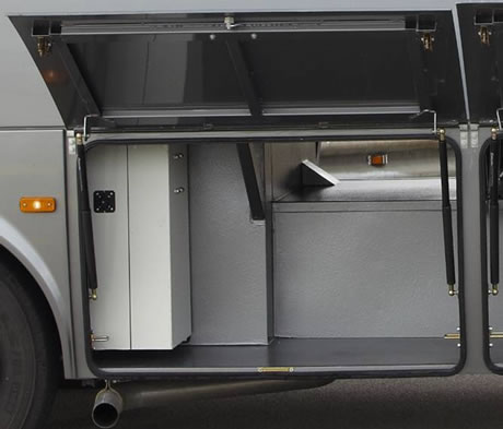
Figure 1. Traditional top-hinged system.
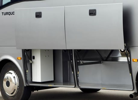
Figure 2. Parallel hinged system.
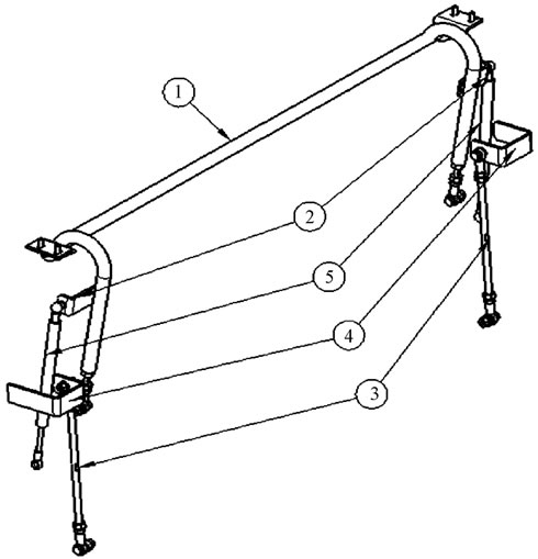
Figure 3. Parts of the mechanism.
bility risk is minimized, because the damper forces act in the compression direction when the door is closed.
3. Kinematics of the Four-Bar Mechanism
Four-bar mechanisms are used extensively and effecttively in industry. A four-bar mechanism is shown in figure 5. The mechanism consists of three moving bars AB, BC and CD with lengths L2, L3 and L4, respectively, pinned at A and D. AD is the fourth bar and has a length of L4. All bars are assumed to be rigid [2]. The objective is to determine the velocity and acceleration of a point and/or angular velocity and angular acceleration of a bar, when the motion of some points and/or bars are known. Either link AB or CD is driven by a motor. Assuming that angle θ2(t) is known, other angles and their first and second derivatives with respect to time should be derived in terms of ,
,  and
and  [3].
[3].
By inspecting figure 5, the closure equation can be
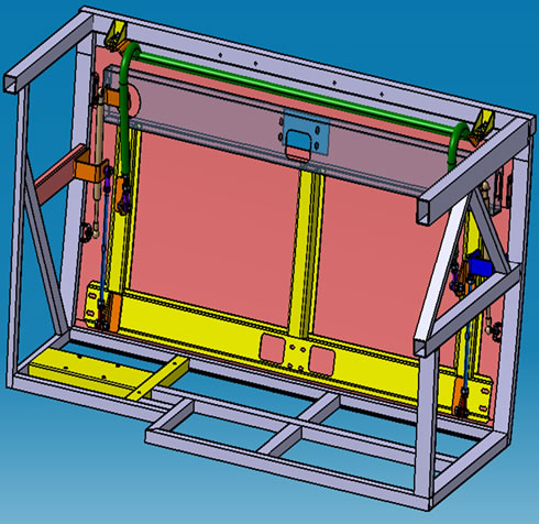
Figure 4. 3D model of the mechanism.

Figure 5. Four-bar mechanism.
written as in (3.1), and its components along and perpendicular to AD can be written as in (3.2) and (3.3), respectively, as
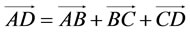 (3.1)
(3.1)
 (3.2)
(3.2)
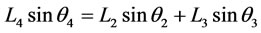 (3.3)
(3.3)
Derivation once with respect to time yields
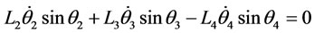 (3.4)
(3.4)
 (3.5)
(3.5)
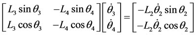
 and
and  can easily be solved for if the numerical values of angles
 ,
,  and
and  are known. In matrix notation, (3.4) and (3.5) become
or

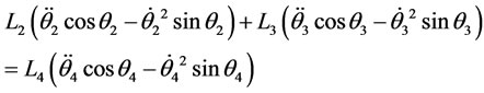
Angular accelerations  and
and  of links BC and DC are obtained by taking the time derivatives of Equations (3.4) and (3.5), respectively.
 (3.6)
(3.6)
 (3.7)
(3.7)
In matrix form

These are nonlinear equations in terms of  and
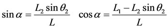
and . Trigonometric identities will be applied to obtain an analytical solution. Basic trigonometric relations can be written in terms of angles α, β and γ as shown in figure 6 [4].
 (3.8)
(3.8)
where
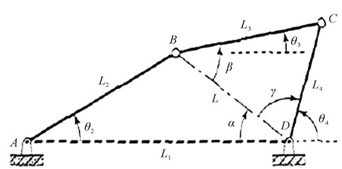
Figure 6. Angles α, β and γ.
 (3.9)
(3.9)
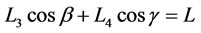
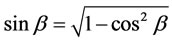
Note that point B can possibly be below AD, if sin α is negative. Next, β and γ are determined using the following expressions written using triangle BCD
 (3.10)
 (3.11)

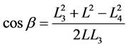 (3.12)
Note that a real solution for  is possible only if
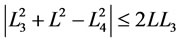 . The mechanism cannot operate for those values of
  that violate this condition. The same is true if the sine and cosine of any angle falls outside the range [−1, 1]. If
  is in the physical range [−1, 1], then there are two possible values
  can have, given in (3.13) and (3.14), each one corresponding to a physical configuration of the mechanism (i.e. with point C either above or below BD in figure 6). The actual solution depends on the initial configuration of the mechanism [5].
Solution 1:
 (3.13)
Solution 2:
 (3.14)
Angles  and
and  shown in Figure 6 are obtained as follows.
 (3.15)
 (3.16)
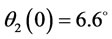
Input values L1, L2, L3 and L4 seen in the red box in figure 7 can be found in Section 4.1. Equations in the blue boxes are equations (4.1)-(4.3) for the opening of the door and equations (4.4)-(4.6) for the closing of the
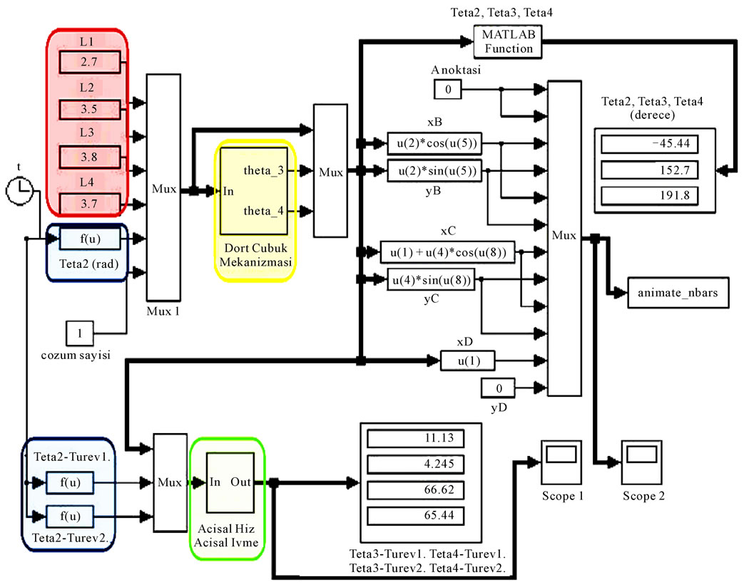
Figure 7. Simulink model of the four-bar mechanism.
door, given in Section 4.2.4. The yellow box can be expanded as shown Figure 8, where (3.9) and (3.12) are used for L and cos β, respectively. All the other equations can be found in section 3.
The green box in figure 7 can be expanded as shown Figure 9, where (3.4) and (3.5) have been used to derive the first derivatives of  and
and  and (3.6) and (3.7) have been used to derive
  and
and .
.
4. Kinematics Analysis of the Design with the Four-Bar Mechanics Approach
4.1. Four-Bar Mechanism Model of the Design
In figure 10, four-bar mechanism analogy of the design is illustrated on the cross section of the mechanism.
As illustrated in figure 10, points A and D are fixed on the mechanism while B and C are the selected design points. The system can be treated as a four-bar mechanism when it is modeled this way. Some physical quantities are as follows.
 ,
,  ,
,
 ,
,  ,
,
4.2. ANSYS Model of the Design
It is important to determine the behavior of a mechanism under a loading condition. Forces acting on the arms, how these forces are transmitted and the joint forces determine the behavior of the mechanism [6].
Variation of θ2 with respect to time should be solved for. In this study, the behavior of the mechanism under a certain loading condition is modeled with the aid of ANSYS, see Figure 11.
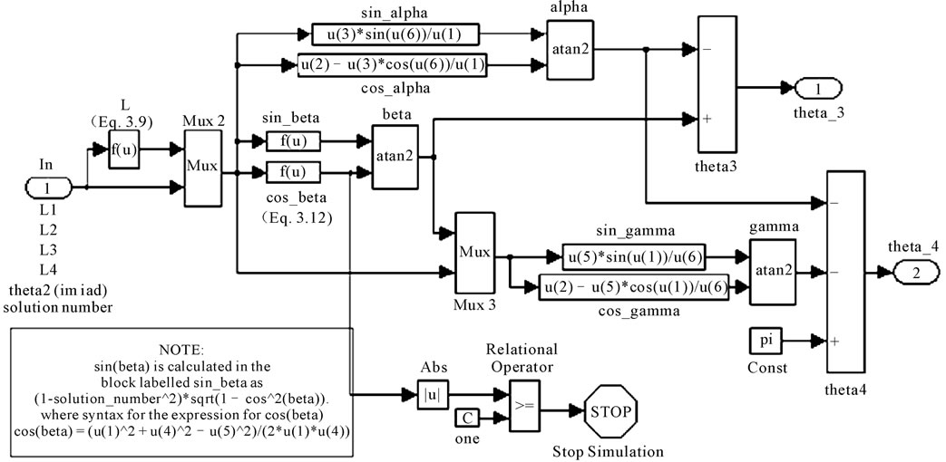
Figure 8. Yellow box in the Simulink model.
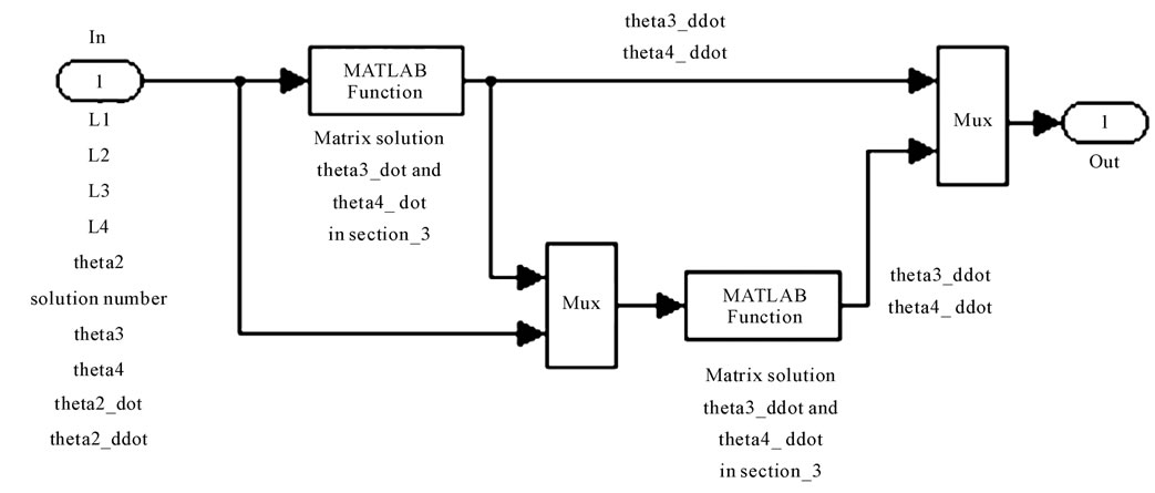
Figure 9. Green box in the Simulink model.
4.2.1. Material Properties
The mechanism is assumed to be rigid. Densities of steel and aluminum are given in the Table 1. The base door is made of aluminum while other parts are made of steel.
4.2.2. Boundary Conditions and Loads
The door frame is fixed to the ground so that all degrees of freedom are restricted. Dampers are modeled as spring elements exerting a force of 300 N in closed position. Motion can be analyzed in two parts. In the opening phase, an external force has to be applied until the gas spring direction passes the neutral axis. After that, the door is opened with the help of the gas springs without an external force. In the closing phase, like in the opening phase, an external force has to be applied until the gas spring direction passes the neutral axis and the door is closed with the help of the gas springs without an external force. Since there are two phases of motion, results are obtained for the two phases separately. When analyzing the opening phase, a force of 100 N is applied to the door handle in the +y and +z directions until the gas spring direction reaches the neutral axis. In the closing phase, a force of 180 N is applied in the –z direction. The applied external force goes to zero after the gas spring

Figure 10. Mechanism cross section and four-bar mechanism.
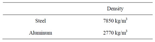
Table 1. Densities of steel and aluminum.
direction reaches the neutral axis in both phases, (see Figure 12).
4.2.3. Geometry
The ANSYS CAD model is seen in figures 13 and 14. The main structure of the trunk lid is made of aluminum sheet and formed to be compatible with the bus side surface. There’re 5 u-profile ribs (3 of them in the z direction, 2 of them in the x direction) made of aluminum and welded on the inner side of the main structure of the trunk lid. These profiles improve the rigidity of the mechanism. The holes placed on these ribs are used to place the locking system parts such as locks, handle, screw, bolt, washer, etc. Parts connected to each other with weld or bolt are imported to ANSYS as a single piece in order to lower the dimensions of the solution matrix. Only the parts that move relative to each other are regarded as separate entities.

Figure 11. ANSYS model of the mechanism.

Figure 12. Force applied in the closing phase.

Figure 13. Spring elements used in modeling the dampers.

Figure 14. ANSYS CAD model.
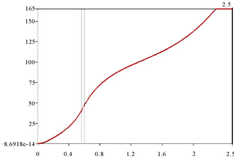
Figure 15. Variation of θ2 in the opening phase.
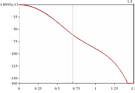
Figure 16. Variation of θ2 in the closing phase.
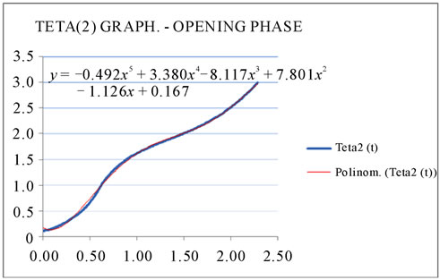
Figure 17. θ2(t) in the opening phase.
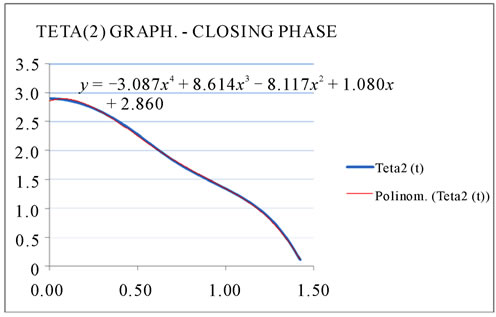
Figure 18. θ2(t) in the closing phase.
4.2.4. ANSYS Analysis Results
Variation of θ2 in the opening and closing phases can be seen in figures 15 and 16.
In figure 15, x axis denotes time in seconds while y axis denotes θ2 in degrees. The luggage door opens 165° in 2.2876 s and stops at that point.
Figure 17 illustrates θ2(t) in the opening phase of the door with a curve fit into the data imported from ANSYS. θ2(0) = 6.6˚ is added to the data taken from ANSYS and the values are converted into radians. A polynomial of fifth order has been fit for θ2(t) in Excel as follows.
 (4.1)
(4.1)
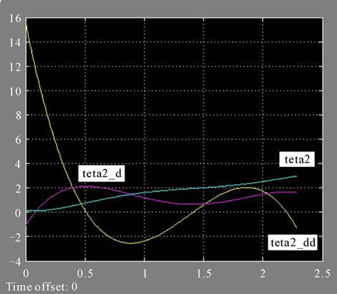
Figure 19. ,
,  ,
,  while opening (angles in radians).
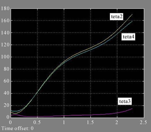
Figure 20. ,
,  ,
,  while opening.

Figure 21. ,
,  ,
,  ,
,  while opening.

Figure 22. ,
,  ,
,  while closing (angles in radians).
First and the second time derivatives are
 (4.2)
(4.2)
 (4.3)
(4.3)
In figure 16, x axis denotes time in seconds while y axis denotes θ2 in degrees. The luggage door closes entirely in 1.4235 s.
Figure 18 illustrates θ2(t) in the closing phase of the door with a curve fit into the data imported from ANSYS. θ2(0) =165˚ is added to the data taken from ANSYS and the values are converted into radians. A polynomial of fourth order has been fit for θ2(t) in Excel as follows.

Figure 23. ,
,  ,
,  while closing.
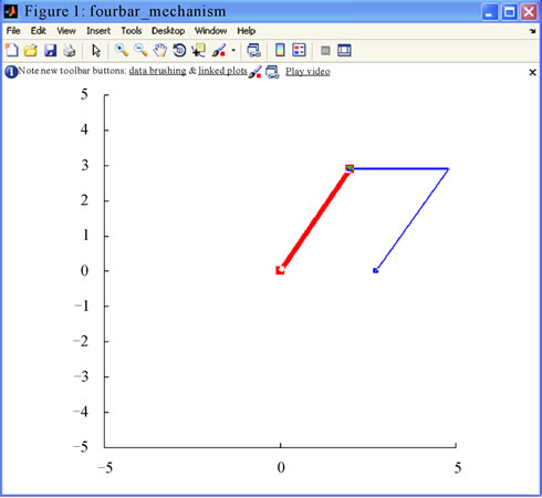
Figure 24. Matlab animation model of the mechanism.

Figure 25. Design cycle.
 (4.4)
(4.4)
First and the second derivatives are
 (4.5)
(4.5)
 (4.6)
(4.6)
4.3. Results of the Kinematics Analysis
In this section, results of the kinematics analysis obtained through a four-bar mechanics approach are presented. Figures 19-23 are plotted by exporting the data obtained from the solutions equations (4.1)-(4.6) to the Matlab model.
Considering the four-bar mechanism shown in figure 5 and the cross-section of the mechanism shown in figure 10, it is seen that the time dependent curves of θ2 and θ4 shown in figures 20 and 23 fit each other. This means that the luggage door has a stable trajectory of motion.
It is seen on the same figures that the amplitude of the θ3(t) curve is nearly equal to zero. This means the door has a trajectory parallel to the sidewall surface of the vehicle.
Considering the trajectory of the luggage door mechanism, position of the gas springs is an important ergonomics criterion for the design. It is observed that the direction of the force vector changes at the point where the rotational acceleration curves shown in figures 19, 21 and 22 change directions. The gas spring force vector passes the neutral axis at that point, so this point is one of the most important criteria of the design, (See Figure 24).
5. Conclusions
In this study, design of a parallel hinged luggage door mechanism and its kinematics analysis are presented.
The design cycle shown in figure 25 has been used in this study to obtain the final design. This cycle is especially used for optimum positioning of the external load points effectively. This way, design objectives of having the minimum working space and operation in narrow spaces in terms of ease of use and ergonomics improvement is achieved.
6. REFERENCES
- W. Paul, “Generic Bus Hatches Presentation Notes, GE Advanced Materials/Global Design & Engineering,” Conceptual Design Development, 2005, pp. 6-8
- G. N. Sandor and A. G. Erdman, “Advanced Mechanism Design,” Analysis and Synthesis, Prentice-Hall, New Jersey, 1984.
- M. R. M. Crespo da Silva, “Intermediate Dynamics,” McGraw-Hill, New York, 2004, pp. 179-198.
- A. A. Shabana, “Dynamics of Multibody Systems,” Wiley-Interscience, New York,1989..
- M. Karkoub and A. S. Yigit, “Vibration Control of a Four-Bar Mechanism With a Flexible Coupler Link,” Journal of Sound and Vibration, Vol. 222, No. 2, 1999, pp. 171-189. doi:10.1006/jsvi.1998.2080
- W. Sunada and S. Dubowsky, “The Application of Finite Element Methods to the Dynamic Analysis of Spatial and Coplanar Linkage Systems,” Journal of Mechanical Design, Vol. 103, No. 3, 1981, pp. 643-651. doi:10.1115/1.3254965