Intelligent Control and Automation
Vol.4 No.2(2013), Article ID:31761,9 pages DOI:10.4236/ica.2013.42028
Dynamic Leveling Control of a Wireless Self-Balancing ROV Using Fuzzy Logic Controller
1Department of Mechatronic and Robotic Engineering, Faculty of Electrical and Electronic Engineering, Universiti Tun Hussein Onn Malaysia, Batu Pahat, Malaysia
2Department of Communication Engineering, Faculty of Electrical and Electronic Engineering, Universiti Tun Hussein Onn Malaysia, Batu Pahat, Malaysia
Email: mohammadafifayob@gmail.com
Copyright © 2013 Mohammad Afif Ayob et al. This is an open access article distributed under the Creative Commons Attribution License, which permits unrestricted use, distribution, and reproduction in any medium, provided the original work is properly cited.
Received December 17, 2012; revised February 4, 2013; accepted February 11, 2013
Keywords: Fuzzy Logic Controller; ROV; Underwater Vehicle; Wireless
ABSTRACT
A remotely operated vehicle (ROV) is essentially an underwater mobile robot that is controlled and powered by an operator outside of the robot working environment. Like any other marine vehicle, ROV has to be designed to float in the water where its mass is supported by the buoyancy forces due to the displacement of water by its hull. Vertically positioning a mini ROV in centimeters resolution underwater and maintaining that state requires a distinctive technique partly because of the pressure and buoyance force exerted by the water towards the hull and partly because of the random waves produced by the water itself. That being said, the aim of the project is to design and develop a wireless self-balancing buoyancy system of a mini ROV using fuzzy logic controller. A liquid level sensor has been implemented to provide feedback to the controller. A user-friendly graphical user interface (GUI) has been developed for real-time data monitoring as well as controlling the vertical position of the ROV. At the end of the project, the implemented fuzzy control system shows enhanced and better performance when compared with one without a controller, a proportional-derivative (PD) controller, and a proportional-integral-derivative (PID) controller.
1. Introduction
A remotely operated vehicle (ROV) is essentially an underwater mobile robot that is controlled and powered by an operator outside of the robot working environment via an umbilical cable or remote control. A ROV differs from autonomous underwater vehicle (AUV) in a way that ROV always take command from its operator and takes no action autonomously. The boundless functionality of modern ROVs have brought great impact to the society from operations in both offshore and inshore by commercial, government, military and academic users.
Like any other marine vehicle, ROV has to be designed to float in the water where its mass is supported by the buoyancy forces due to the displacement of water by its hull. The provision of special tankage is required for the transition from surface to submerge and to sustain the balance between mass and buoyancy while submerges. The changes in buoyancy occur corresponding to the deepness the vehicle travels consequently making the state of equilibrium in depth tends to be unstable with the vessel at rest. Since changes in buoyancy occur with depth, vehicle structures, including the hull, lose displacement as they compress [1] and thus will affect its vehicle stability. Subsequently, a special control device would have to be provided for the vessel to stay at a particular level.
The main problem in current ROV model circulates around the leveling control of the vehicle’s negative buoyancy condition. Vertically positioning a mini ROV in centimeters resolution underwater and maintaining that state requires a distinctive technique partly because of the pressure and buoyancy exerted by the water towards the vessel and partly because of the random waves produced by the water itself. The study and design of a self-leveling system for a ROV is significantly important because of numerous applications that can take merits from it, such as subsea installations, inspecting the hazardous inside of nuclear power plants, object location and recovery, and repairing complex deep water production systems.
2. Related Work
There are different methods that have been applied by previous researchers in constructing a ROV. Reference [2] presented the development of a dynamic buoyancy control of a tethered ROV using a variable ballast tank. The dynamic buoyancy control solution for the smallscale ROV is a pneumatic system that includes an airfilled ballast tank. The source of the air is a surface tank that is brought to the ROV through a single hose in ROV’s tether and is always pressurized.
Reference [3] studied an underwater mobile robot with a buoyancy control system based on the spermaceti oil hypothesis originated back in 1970s [4]. The hypothesis insists that sperm whales melt and congeal their spermaceti oil that is located in their head and change the volume of the oil to control their own buoyancy. It is noted that although the mobile robot can surface and submerge, it is not able to control depth and at least following problems must be solved to tackle this matter. First, sensors to detect depth of the robot, such as a pressure sensor, must be added to the robot. Second, the heating method should be improved to shorten the time for melting paraffin wax, because the response time will affect robot's depth control ability greatly. Additionally, temperature of the paraffin wax should be controlled to regulate wax's volume and robot’s buoyancy precisely.
Reference [1] developed a variable buoyancy control system (VBS) for a large AUV to launch in shallow water (<10 m) and to hover without propulsion. The vehicle is equipped with two VBS tank to meet these requirements. The resulting control problem is that the control variable, pump rate, is proportional to the third derivative of the sensed variable, depth; there are significant delays, and forces are nonlinear (including discontinuous) and highly uncertain. The AUV is launched from the surface using the VBS depth controller implementing a proportional derivative (PD) type of control law in conjunction with the fins, once fin authority is attained. Logic and filtering are used to sequence operational modes and to reject low-frequency disturbances such as waves. While this depth control strategy is shown to be more than adequate to launch the vehicle, it cannot hovers due to the limit time cycle.
A long cruising range AUV equipped with a VBS system was developed in reference [5]. The VBS of the long cruising range AUV was constructed with an oil tank which can bear the ambient sea water pressure when it works in 1000 m depth, a rubber bladder which can regulate its displacement volume and a set of hydraulic driving system. When the VBS computer receives the buoyancy adjustment command from the operator, it calculates the number of pump revolutions according to the ambient pressure of the AUV and then sends the pulse width modulation (PWM) signals to the driver of the DC motor.
3. Methodology
3.1. Fuzzy Logic Controller
There are various controller design theories that can be used to maintain the leveling control of the mini ROV system such as fuzzy logic controller, PID controller, adaptive controller, pole placement, linear quadratic regular (LQR), and robust control. In this study, fuzzy logic controller is used to control the vertical motion of the mini ROV. The components of fuzzy logic controller are shown in Figure 1. It generally comprises of four principal modules; fuzzifier, knowledge base, inference engine, and defuzzifier.
Several phases have been conducted to design the fuzzy logic controller. Such phases include:
1) Selecting the control variables for input and output.
2) Choosing the inference mechanism.
3) Setting the fuzzification method.
4) Designing the knowledge base.
5) Selecting the defuzzification method.
6) System testing and fine-tuning.
By fuzzifying crisp input data into linguistic sets, fuzzy controller allows an automatic control strategy to be established based on ingenious knowledge [6]. In fuzzy logic controller, the developer has to set the rules for the rule-based system. Fundamentally, the fuzzy rulebased comprises of the following If-Then rules If xi is A1, Then y is B1, where A1 and B1 are fuzzy sets in  and
and  respectively and X = (x0, x1,…,xn)
  is the input variable of the fuzzy system while
  is the output variable of the fuzzy system. For the fuzzy logic controller in this mini ROV, the input to the fuzzy system is the depth the mini ROV will submerge or surface depending on the operator. Mamdani method is used as the inference engine while the center of gravity (COG) is used as the defuzzification method. The output of the fuzzy system is then used as the time reference for the DC pumps to operate.
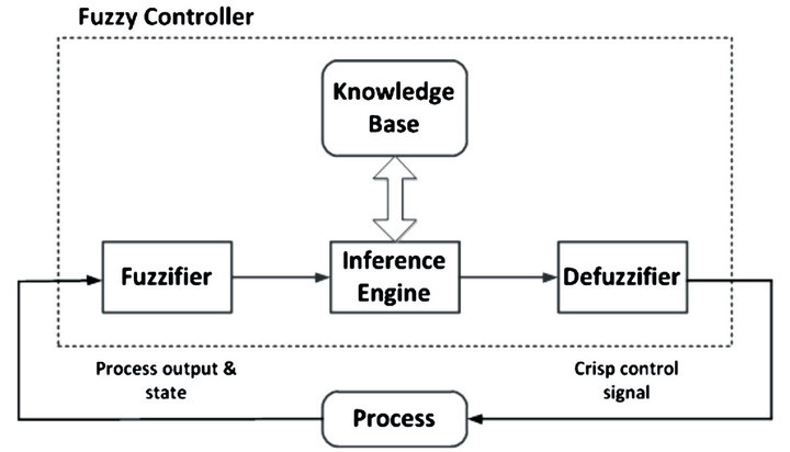
Figure 1. Components of fuzzy logic controller.
A single fuzzy logic controller as designed in Figure 2 with two input and single output is employed to control the mini ROV system. The fuzzy associative memory matrix (FAMM) that is used in the system is shown in Table 1 while the membership function is shown in Figure 3. The recognized advantage by using fuzzy controller is it can cope with nonlinear system, does not require a formal mathematical method, and able to produce faster and better response than a conventional PD controller [7].
3.2. Mechanical Design
The mini ROV was designed by using SolidWorks with
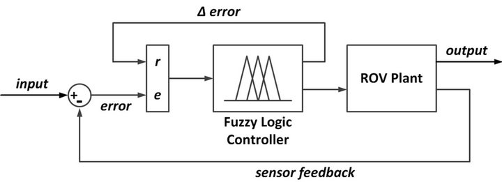
Figure 2. Vertical positioning of a mini ROV control using fuzzy logic controller.
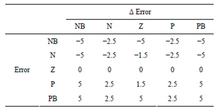
Table 1. Fuzzy associative memory matrix (FAMM).

Figure 3. Membership function for error and delta error.
every details and considerations taken into account. The design as in Figure 4 had two separated hull; the lower partition to accommodate the water intake while the upper for the placement of electronic components. Since fluid pressure increases with depth and that the increased pressure exerted in all directions, thus there is an unbalanced upward force on the bottom of a submerged object [8]. To overcome this problem, four small cylindrical hulls are strategically placed around the main structure to further provide stability when the mini ROV is submerged into water. These hulls also help in increasing its positive buoyancy to compensate the weight of the mini ROV.
The total weight including the electronics is 1.9 kg while the overall size is within 61 cm height and 31 cm wide. The main body was made by using a combination
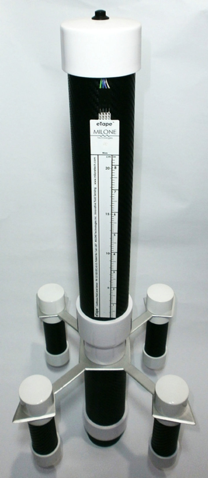
Figure 4. Mini ROV physical construction.
of various size of polyvinyl chloride (PVC) pipe. A push button to switch the system ON/OFF is located at the top. There is a blue light emitting diode (LED) that lights up to indicate that the system is ON and a blinking red LED to indicate that data transmission is operating. The liquid level sensor is attached to the outer part of the body so that it can give feedback of its current level. All of the remaining electronics including the water pumps are placed inside the mini ROV.
To maintain the atmospheric pressure inside the mini ROV whenever water is pumped in or out, a small hole has been made at the top of the upper structure. Although this limits the movement of the mini ROV to be just partially immersed, it is well adequate to study the working concept of this project.
A steel cylindrical rod that weighed 700 gm with a size of 8.9 cm height by 4.5 cm in diameter is placed inside the lowest structure of the ROV. The main purpose of the steel is to provide enhance stability when the whole structure is submerged as shown in Figure 5. Initial observation proves that if the steel rod is removed from the body, the mini ROV is not capable to stay vertical when it is placed underwater.
3.3. Graphical User Interface (GUI)
The GUI as shown in Figure 6 has been developed by using MATLAB for controlling and monitoring the mini ROV system in this project. The GUI is turned ON by pushing the push button switch and the input data to mini ROV is given through an input box. The input data is in form of integer with a range of −9 to 9. The GUI is equipped with a display box fordisplaying the current level and the real-time response of the mini ROV. The
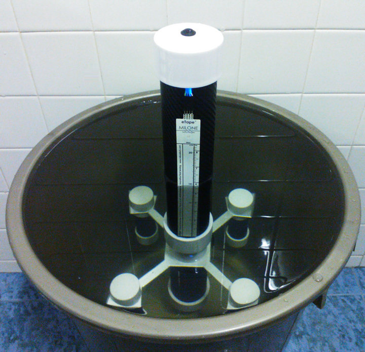
Figure 5. Submerging mini ROV underwater.
response data is captured in a form of graph with a maximum of two minutes runtime. The process can be repeated as many times as desired by simply pressing the push button after the runtime is over.
4. Results
4.1. Micro Pumps Performance
A simple test to run each of the DC pumps for one minute has been conducted to obtain its flow rate capacity performance. A small calibrated cylinder with a maximum of 120 ml capacity is used to measure the volume of the tap water being pumped out of the motor. The findings are presented in Table 2. During the experiment, motor pump 2 produces 67 to 85 ml/min flow rate while motor pump 1 produces 34 to 42 ml/min flow rate at 5 V DC supply. In addition, the other noticeable discoveries were that both pumps contribute to inconsistent and non-linear flow rate especially for motor pump 2

Figure 6. ROV GUI for level control and data monitoring.

Table 2. Flow rate capacityfor micro pumps.
even though all other variables have been made constant. Based on the obtained results, the motors are suspected to have manufacture defects.
4.2. Liquid Level Sensor
The mini ROV has been tested to maintain its level at 15 cm every time it is turned ON while being submerged underwater to get the reading consistency of the liquid level sensor. The experiment is repeated for 10 consecutive times and the findings are given in Table 3. It can be seen that the largest error only happened once during the second reading with an excess of 0.24 cm from the desired level. This reading may be because of the human error or the measuring mechanism.
Other test result also produced error that is still tolerable ranging from 0.06 cm to 0.18 cm. Further observation has brought to the discoveries that the main cause for the error in the system is due to the extremely high sensitivity of the liquid level sensor. It has come to the knowledge that while measuring water level at a constant depth, the sensor will produce completely different readings whenever there is a slight bend acted towards the sensor. For that reason the sensor has been taped along its side to the mini ROV structure to prevent the aforementioned situation from becoming worse. Besides that, the error might also occurred because of the water characteristic that makes it tend to stick to the sensor and hence produce different readings whenever the mini ROV is submerged.
4.3. Software Development
4.3.1. Fuzzy Logic Control
A mini ROV system without a controller has been simulated by using MATLAB Simulink to be compared with the designed fuzzy logic controller of this project as shown in Figure 7. The following result in Figure 8 shows the simulated response which is extremely unstable; it cannot reach the set point. The response produced an extremely large error of 671.9 as oppose to the 15 unit of reference input. To solve the problem, fuzzy logic control as a feedback controller is applied in order to make the system stable.
Fuzzy logic control for a mini ROV has been developed with two inputs and a single output.The simulation block and result are shown in Figures 9 and 10 respectively. The leveling of a mini ROV was set to be 15 cm underwater and was implemented as a unit step with a step value of 15. The result shows that the system response took 0.19 s to reach its reference target and iscapable to maintain its steady state output without any error.
Side-by-side block and response comparison between the fuzzy logic control system with a PD control system and PID control system of a mini ROV has been simulated as given in Figures 11-14. A unit step with a value of 15 was chosen as the input variable. The time taken to reach the set point for each control system were 1.39 s for PD control system, 1.80 s for PID controller system and 0.19 s for fuzzy logic control system. Between these three controllers, only the PID controller having the large overshoots of 42.67%.
4.3.2. Real-Time Response
Controlling and monitoring the real-time performance of the mini ROV system in this project is done via the MATLAB GUI. Several tests have been conducted to see the response of the system and the results are shown inFigures 15-19. The input for the system is manually sent at different time after the GUI is turned ON during each run.
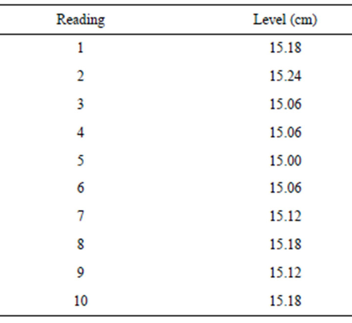
Table 3. Mini ROV level consistency test.
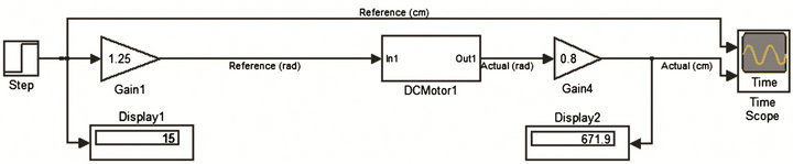
Figure 7. Simulated open loop controller for mini ROV leveling control system.
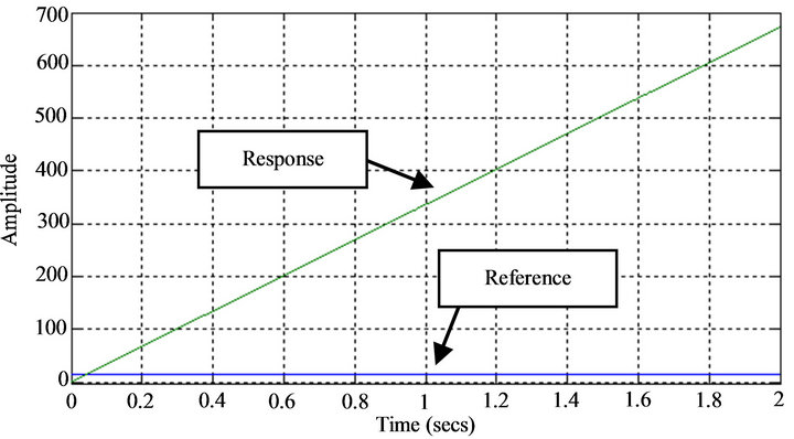
Figure 8. A mini ROV open loop response.
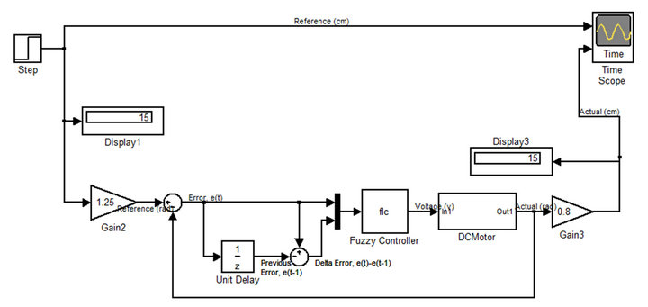
Figure 9. Fuzzy logic control block.
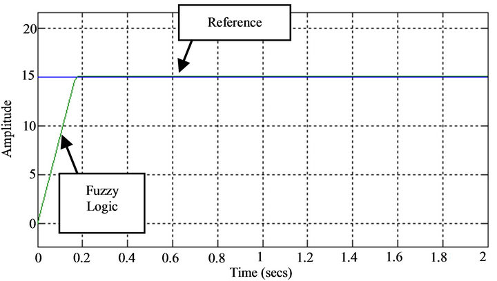
Figure 10. Fuzzy logic control system response.
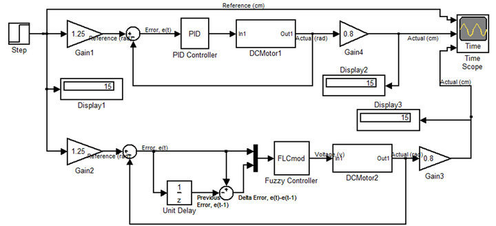
Figure 11. Fuzzy logic control and PD control block.
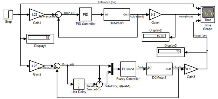
Figure 12. Fuzzy logic control and PID control block.
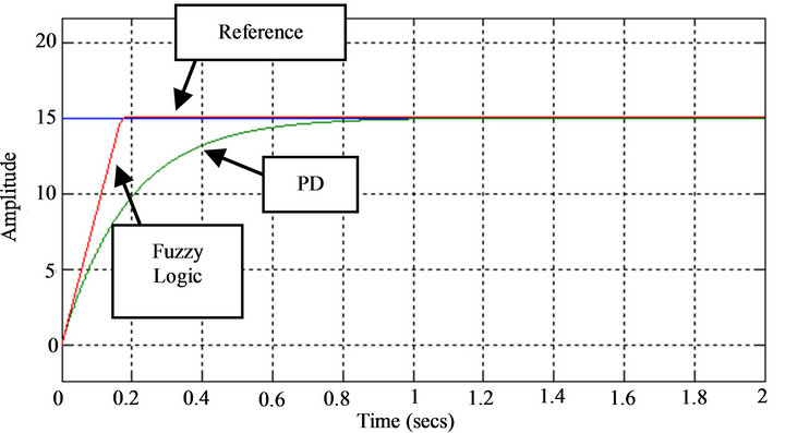
Figure 13. Comparison of output response between fuzzy logic control and PD control system.
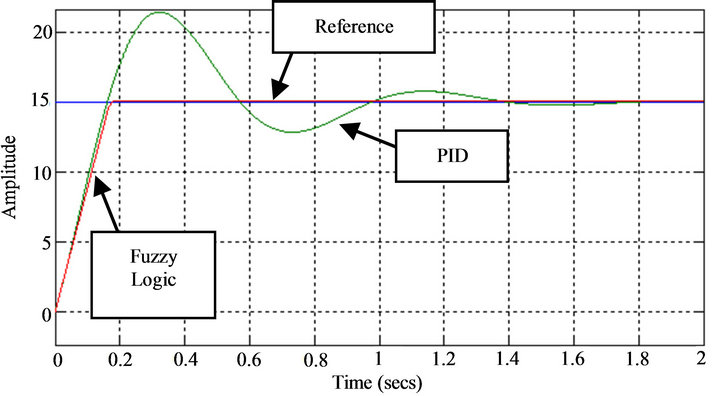
Figure 14. Comparison of output response between fuzzy logic control and PID control system.

Figure 15. ROV rising response from 0 cm to 1 cm.

Figure 16. ROV sinking response from 1 cm to 0 cm.
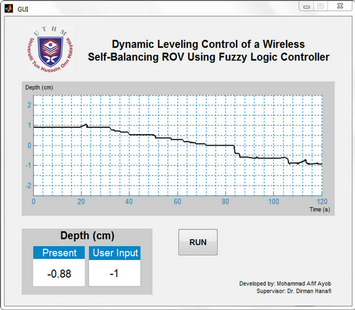
Figure 17. ROV sinking response from 1 cm to −1 cm.
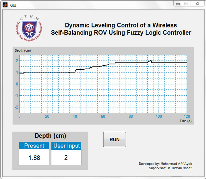
Figure 18. ROV rising response from 1 cm to 2 cm.

Figure 19. ROV sinking response from 2 cm to 0 cm.
Based on the real-time tests of the mini ROV as displayed on the GUI, it can be seen that the final reading of the mini ROV as displayed on the GUI is not exactly the same as the input every time the tests were conducted. However, it is substantially satisfactory as it only produced an error of 6% as in Figure 15, 4% as in Figure 16, 12% as in both Figures 17 and 18, and 18% as in Figure 19. In average, all these errors only contribute to 10.4% for the mini ROV system in this project. The known reasons for the mentioned errors include:
1) High sensitivity of the liquid level sensor that is prone to produce different readings at unexpected moment.
2) Continuous varied performance for water pumps flow rate capacity.
3) Water concentration that is likely to stick to the liquid level sensor and thus giving false readings.
4) Possibility of water leakage on the mini ROV construction.
5. Conclusions
A mini ROV with GUI controlling and data monitoring has been successfully developed by using fuzzy logic controller. Based on the simulation and analysis results, fuzzy logic controller gives faster performance with 0.19 s to reach the set point compared to PD and PID controller with 1.39 s and 1.80 s respectively. Unlike the PID controller that produced 42.67% overshoot, the designed controller in this project has none which makes it a better controller for controlling and balancing the level motion of a mini ROV.
From the given simulations carried out in MATLAB and proven workability in real-life application, the system could be refined and fine-tuned to cope with a more complex and large ROV system in specialization of performing specific task.
6. Acknowledgements
This work has been supported by the Faculty of Electric and Electronic Engineering, Universiti Tun Hussein Onn Malaysia.
REFERENCES
- S. Tangirala and J. Dzielski, “A Variable Buoyancy Control System for a Large AUV,” IEEE Journal of Oceanic Engineering, Vol. 32, No. 4, 2007, pp. 762-771. doi:10.1109/JOE.2007.911596
- K. S. Wasserman, J. L. Mathieu, M. I. Wolf, A. Hathi, S. E. Fried and A. K. Baker, “Dynamic Buoyancy Control of an ROV using Variable Ballast Tank,” Proceedings of OCEANS 2003, California, 22-26 September 2003, pp. 2888-2893.
- K. Shibuya, Y. Kado, S. Honda, T. Iwamoto and K. Tsutsumim, “Underwater Robot with a Buoyancy Control System Based on the Spermaceti Oil Hypothesis,” Proceedings of the 2006 IEEE/RSJ Interational Conference on Intelligent Robots and Systems, Beijing, 9-15 October 2006, pp. 3012-3017.
- M. R. Clarke, “Buoyancy Control as a Function of the Spermaceti Organ in the Sperm Whale,” Journal of the Marine Biological Association of the United Kingdom, Vol. 58, No. 1, 1978, pp. 27-71. doi:10.1017/S0025315400024395
- W. Zhao, J. Xu and M. Zhang, “A Variable Buoyancy System for Long Cruising Range AUV,” 2010 International Conference on Computer, Mechatronics, Control and Electronic Engineering (CMCE), Harbin, 24-26 August 2010, pp. 585-588.
- M. Xu, “Adaptive Fuzzy Logic Depth Controller for Variable Buoyancy System of Autonomous Underwater Vehicles,” Proceedings of the 3rd IEEE Conference on Fuzzy Systems, Florida, 26-29 June 1994, pp. 1191-1196.
- M. A. Salim, A. Noordin and A. N. Jahari, “A Robust of Fuzzy Logic and Proportional Derivative Control System for Monitoring Underwater Vehicles,” 2nd International Conference on Computer Research and Development, Melaka, 7-10 May 2010, pp. 849-853. doi:10.1109/ICCRD.2010.187
- R. Nave, “Pressure,” 1998. http://hyperphysics.phy-astr.gsu.edu/hbase/pbuoy.html