Circuits and Systems
Vol.07 No.09(2016), Article ID:68548,17 pages
10.4236/cs.2016.79193
Detection of Link Fault Using Risk Modelling and Improving QOS Parameters in IP/WDM Networks
K. Sashi Rekha1*, M. Sumathi2
1Department of Information Technology, R. M. K. Engineering College, Thiruvallur, India
2Department of Electronics and Communication Engineering, Dhirajlal Gandhi College of Technology, Salem, India

Copyright © 2016 by authors and Scientific Research Publishing Inc.
This work is licensed under the Creative Commons Attribution International License (CC BY).
http://creativecommons.org/licenses/by/4.0/


Received 2 May 2016; accepted 15 May 2016; published 18 July 2016
ABSTRACT
An operational backbone network is connected with many routers and other devices. Identifying faults in the network is very difficult, so a fault localization mechanism is necessary to identify fault and alleviate it and correct the faults in order to reduce the network performance degradation. A risk model needs to be devised based on the dynamic database by creating alternate path and the network is reconfigured by identifying dynamic paths. In this paper, an on-demand link state routing approach is used for handling failures in IP backbone networks and a localization algorithm is used to improve QOS parameters based on threshold value of gateway. It is proved that on-demand link state routing guarantees loop-free forwarding to reachable destinations regardless of the number of failures in the network, and in case of localization algorithm using modification process packet loss is avoided based on threshold value of gateway. Heuristic algorithm is also used for reconfiguration of dynamic path for effective fault localization. In this paper, in order to change the traffic condition, reconfiguration strategic is dynamically used. Dijikstra’s shortest path algorithm has been used to determine the shortest path between node pairs. Using risk modeling mechanism, a small set of candidate faults is identified. The concept of Fault Localization is used to minimize the fault occurring in the node and sends original path to node pairs. The localization algorithm based on MODIFICATION PROCESS, packet loss is avoided in the network by checking threshold value of gateway. If the threshold value is maximum, router directly forwards the packet to destination through gateway and if the threshold value is minimum, router compresses the packet and forwards the packet to destination with notification via gateway.
Keywords:
Virtual Topology Reconfiguration, Load Balancing, Localization Algorithm, On-Demand Link State
Routing, Localization Algorithm Based Modification

1. Introduction
This paper provides simulation results by using two different approaches, on-demand link state routing approach and localization algorithm based on the modification process; we present results of detailed simulations. To enable this simulation, we use ns-2 simulator. ns-2 is a discrete event simulator, and it provides substantial support for simulating IP based WDM network model over conventional network model and no support for accurately simulating the physical aspects of WDM network or the protocols needed for this environment and there is no spatial diversity and it can model only directly connected nodes. Some of the changes made to ns-2 to allow accurate simulation of IP based WDM network.
The different cross networking layers like IP, optical Network etc., undergo various low level failures, which are very difficult to detect. Changes in technology necessitate development of risk models for efficient fault localization in various layers, and also require dynamic databases. Hence, fault across IP over optical network should be identified dynamically. A risk model based on dynamic databases can be designed, in order to compute light paths dynamically and lead to efficient fault localization risk model. Spatial correlation algorithm is used for IP fault localization within a controlled environment by using emulated faults which can automatically identify likely root causes across layers [1] .
Belief networks can be used to implement fault localization in communication systems taking into account comprehensive information about the system behaviour but this is time consuming and requires substantial amount of resources [2] . It also suggests that alarm correlation is another approach for interpretation of multiple alarms such that, a new meaning is assigned to these alarms. It is a generic process that underlies different network management tasks such as context-dependent alarm filtering, alarm generalization network fault diagnosis, generation of corrective actions. Hierarchical domain-oriented reasoning mechanism is also suitable for the delegated management architecture. It is based on the causality graph of the sensibly-reduced network fault propagation model from the result of empirical study. An automated fault diagnosis system called AC View (Alarm Correlation View) is used for isolating network faults in a multi domain environment according to the hierarchical reasoning mechanism. But diagnosing more complex problems is very difficult using this approach [3] .
LDP (Label Distribution Protocol) and MPLS (Multi-Protocol Label Switching) in general do not have intrinsic means for detecting failures. New mechanisms are introduced to handle them. Furthermore, the IGP (Interior Gateway Protocol) may remain unaware of the LDP failure, and continue to direct traffic to the faulty path. To resolve this situation, coupling between LDP and the routing protocol is introduced. But LDP requires manual configuration on each interface [4] .
In this paper, on-demand link state routing algorithm calculates the direction and distance to any link in a network. The direction usually means the next hop address and the exit interface. Distance is a measure of the cost to reach a certain node. The least cost route between any two nodes is the route with minimum distance. Each node maintains a table of minimum distance to every node. The cost of reaching a destination is calculated using various route metrics [5] . The node can identify the link bandwidth and number of connected nodes. So based on this analysis, the node can share the bandwidth availability to neighbour nodes. In this paper, we calculate bandwidth availability based on the number of users. The node which wants to make the communication will check the multi-route sharing bandwidth, the node which provides more bandwidth sharing will select the route through that path.
1.1. Localization Algorithm Based Modification Process
Localization algorithm is used to identify, source node in the network that forwards the data packet to gateway through router to reach the destination node. The network is interconnected with router nodes and gateway. Each router in the network exchanges periodic messages to the router at the other end, which then acknowledges the receipt of the message. Even if there is a failure in the link/energy drain out in the router the network must automatically reconfigure and take alternate route for the data forwarding to destination through gateway using localization algorithm.
1.2. Modification Process
In the MODIFICATION PROCESS, we are avoiding packet loss in the network based on checking threshold value of gateway. If the threshold value is maximum, router directly forwards the packet to the destination through gateway. Suppose if the threshold value is minimum, router compresses the packet and forwards the packet to the destination with notification via gateway.
The remainder of this paper is structured as follows. Fault-localization introduction is presented in Section 2. Problem Statement is defined in Section 3. Fault localization method using on-demand link state routing algorithm is explained in Section 4. Localization algorithm based modification process is available in Section 5. Simulation results and discussion are shown in Section 6. Finally, Section 7 concludes and discusses the future work.
2. Fault Localization
To identify fault in IP based WDM network we need to devise a risk model which can be based on database that can compute path dynamically [6] . Integrated routing which already exists can be used to invoke various WDM network services. The automated provisioning of paths are analysed within the sub network, and then each link state update route computation and path establishment are updated dynamically. In order to dynamically restore paths across optical sub networks, on-demand link state routing algorithm calculates the direction and distance to any link in a network. The direction usually means the next hop address and the exit interface. Distance is a measure of the cost to reach a certain node. The least cost route between any two nodes is the route with minimum distance. Each node maintains a table of minimum distance to every node.
Localization Algorithm Based Modification Process
Localization algorithm is used to identify, source node in the network that forwards the data packet to gateway through router to reach the destination node. The network is interconnected with router nodes and gateway. Each router in the network exchanges periodic messages to the router at the other end, which then acknowledges the receipt of the message. Even if there is a failure in the link/energy drain out in the router the network must automatically reconfigure and take alternate route for the data forwarding to destination through gateway using localization algorithm. Risk modelling is devised as shown in Figure 1.
3. Problem Statement
In case of on-demand link state routing, while designing the physical layer, the factors considered are overall traffic distribution, link cost, and the location of the nodes. To design virtual topology these factors are essential to be supported by the physical topology. Therefore, the physical topology needs to be designed with some knowledge of the traffic it supports [7] . In this paper we propose a design which automatically generates a virtual topology for the given physical topology considering the IP address for the network devices (nodes, switches, routers) as their base for the reconfiguration procedure.

Figure 1. Risk modelling for fault localization.
The packets sent from the source node should reach the destination properly. When there is a link failure, the packet should take up an alternate route based on the traffic [8] . So that, the packet data remains confidential from other users. The packets sent from source should reach the destination within some particular time constraints.
In localized algorithm, we propose a source node in the network that forwards the data packet to gateway through router to reach the destination node. Each router in the network injects periodic messages to the router at the other end, which then acknowledges the receipt of the message. Even if there is a failure in the link/energy drain out in the router the network must automatically reconfigure and take alternate route for the data forwarding to destination through gateway based on IP over WDM technique using localization algorithm.
Modification Process
In the MODIFICATION PROCESS, we are avoiding packet loss in the network based on checking threshold value of gateway. If the threshold value is maximum, router directly forwards the packet to the destination through gateway. Suppose if the threshold value is minimum, router compresses the packet and forwards the packet to the destination with notification via gateway.
4. On-Demand Link State Routing Algorithm
4.1. Physical Topology Design
Physical Topology shown in Figure 2 is a connection of network devices (Nodes, Switches, Routers).
The set of nodes and the set of physical links constitute the physical topology [9] . Whenever a device is created the details of the device is stored in the database (SQL server). It involves assigning IP address to the devices that are to be connected physically. The traffic generation parameter values are randomly generated (Xval, Yval).The physical link may be bidirectional, and every fiber link carries a certain number of wavelengths.
4.2. Virtual Topology Design
In order to maximize the network performance, the nodes between which the lights paths are to be established must be carefully chosen. The virtual topology design involves determining the virtual topology for the given physical network as shown in Figure 3, routing the light paths over the physical network, wavelength assignment and routing of traffic over the virtual topology [9] .
The in-degree and out-degree of a physical topology node are  and
and  [1] .
[1] .
The in-degree and out-degree of a Virtual topology node are  and
and  [1] .
[1] .
W, is the number of wavelength in a link.
Then,
 (1)
(1)
 (2)
(2)

Figure 2. Physical topology.

Figure 3. Virtual topology.
4.3. Route Discovery
Our protocols are based on calculating the direction and distance to any link in a network. Direction usually means the next hop address and the exit interface. Distance is a measure of the cost to reach a certain node. The least cost route between any two nodes is the route with minimum distance. Each node maintains a table of minimum distance to every node. The cost of reaching a destination is calculated using various route metrics.
・ Routing table update.
・ Based on Bandwidth availability.
In our proposed protocol, the node can identify the link bandwidth and number of connected nodes. So based on this analysis the node can share the bandwidth availability to neighbour nodes.
The bandwidth availability is calculated based on the number of users.
Nodes are connected by the link, and each link has certain bandwidth limit. In the Figure 4, there are nodes A, B, C, D, E and F connected. Consider the connection between A and B has the bandwidth of 20 Mb and B-C has the bandwidth 20 Mb and C-E has 30 Mb and C-D has 25 MB and C-E has the bandwidth limit 40 Mb.
While making the update the node C will measures the sharing bandwidth limit as:
 (3)
(3)
The formula, defines Bsh, the sharing bandwidth, Bln the link bandwidth and N, number of node which is connected to the node.
After updating the node which wants to communicate, will check the multi-route sharing bandwidth, the node providing more bandwidth sharing will select the route through that path.
4.4. Route Maintenance
This is done to implement the error message sharing when the node link fails. The main aim of our system is to avoid unnecessary error message sharing and to avoid the looping we use the routing list with the block list [10] .
The nodes maintain the routing list; the block list is initialized with null value at initial time. Whenever the node link fails then the node will mark it as blocked node in blocked list until the route rectification, this block list route will be maintained until the entire route to that node will get break.
To avoid overhead in the network, each node, which is connected with the broken link, will find the problematic node. Here, we define the problematic node as the node which gets affected by the failure.
Let us consider the node connected by the wired link as shown in Figure 5.
In our proposed model, we implement a method, to reduce the overhead on congestion in the network. And eliminate looping.
Each link’s state is advertised with the labelled cost, but currently the dashed links are labelled with cost ∞ and assuming that the nodes adjacent to a dashed link are aware of its current failed state [10] . If a link’s current cost is worse than advertised, local rerouting around that link can cause loops. On the other hand, if a link’s current

Figure 4. Connected network.

Figure 5. Nodes connected by the wired link with bandwidth.
state is better than advertised, forwarding over that link is loop-free. Hence, we focus only on degraded links, Table 1 shows the Routing Table of Node A with maximum bandwidth and Hop count.
As an alternative, we propose On-demand link state routing which includes degraded links that cause a dead end in the packet itself so that forwarding by intermediate routers is loop-free.
Under on-demand link state, a packet can be thought of as being forwarded in two modes: greedy and recovery. A packet is normally forwarded in greedy mode to a next hop along the path with decreasing cost (w.r.t. the advertised topology) to the destination. When a packet hits a dead end in greedy mode, instead of discarding the packet, it is forwarded in recovery mode. In recovery mode, packets carry a blacklist, which is a set of degraded links encountered along the path. A packet’s next hop is chosen along a route that does not include blacklisted links. The forwarding of a packet is switched back to greedy mode, i.e., the blacklist is reset to empty, when it arrives at a node with lower cost (w.r.t. the advertised topology) to the destination than the node at which it entered the recovery mode. Thus, on-demand link state effectively propagates link state on demand and only to as many nodes as necessary. This approach ensures loop-free forwarding to reachable destinations, even in the presence of many degraded links. This is explained using flowchart (Figure 6) for on-demand Link state Approach.
4.5. Algorithm
1) If new link is detected at any node:
a) Collects the properties of the link.
b) Checks the Number of connections available in node.
c) Calculate the cost by combining the bandwidth, delay and number of connections and hop count.
d) Create the route message with node id, cost, and RT (routing table) information. And send to available
neighbor nodes.
2) If node received any route message:
a) Checks fields of routing message.
b) Update the routing table with:
i) Neighbor detail based on cost.
ii) Neighbors neighbor details based on cost.
3) If any data packet is generated:
a) Checks whether RT info is available.
i) If yes.
1. Go to next hop selection process (step 5).
ii) Else if no.
2. Go to route discovery process (step 4).
4) Route discovery:
a) Create and broadcast the message with detail of destination.
b) If packet received:
i) Neighbor is the destination or it has the route to destination, then it will reply back to source with route update.
5) Next hop selection:
a) Collect the multiple route info from RT.
b) Shortlist the info based on the cost of link and route.
c) Select the node which is with low cost
6) If link failure is detected:
a) Check whether node has the packet to send through failed link.
i) if yes.
1. check the next level node based on step 5.
2. Update the Blacklist field of the packet.
3. Send to next hop node.
ii) Else if.
1. Generate the Route error message with failed link and send to neighbor.
7) If packet is received:
a) Checks the packet type.
i) If Data packet.
1. Check blacklist status.
b) If yes.
i) Do blacklist processing (step 8).
c) If no.
i) Forward the data.
ii) If route error packet.
1. Do blacklist processing (step 8).
8) Blacklist processing:
a) If blacklist index is less than maximum possibility.
i) Update the blacklist in the routing table.
1. Add the info of failed link from the packet and increase the failure index value.
2. Check whether problematic node is found or not based on.
a) Forward connection.
b) Reverse connection.
3. If problematic node found.
a) Generate the error message and send to problematic node.
4. If not.
a) Ignore the packet.
b) Else.
i) Update the Route blacklist (step 8.a).
ii) Drop the data packets as well as error packet.

Table 1. Routing table of node A.

Figure 6. Flowchart for on-demand link state approach.
5. Localization Algorithm
Localization is one of the most important technologies since it plays a critical role in many applications, e.g., target tracking [2] . If the users cannot obtain the accurate location information, the related applications cannot be accomplished. The main idea in most localization methods is that some deployed nodes (landmarks) with known coordinates transmit beacons with their coordinates in order to help other nodes localize themselves. In this paper, we reclassify the localization algorithms with a new perspective based on the unknown nodes and present a detailed analysis of the representative localization algorithms. Node localization is required to report the origin of events, routing and to answer questions on the network coverage. To achieve higher localization accuracy, extra hardware equipments are utilized by most of the existing localization algorithms, which increase the cost and greatly limit the range of location-based applications. In this paper we present a method which can effectively meet different localization accuracy requirements of most indoor and outdoor location services in realistic applications. Our algorithm is composed of two phases: partition phase, in which the target region is split into small grids and localization refinement phase in which a higher accuracy location can be generated by applying a trick algorithm. A realistic demo system using our algorithm has been developed to illustrate its feasibility and availability. The results show that our algorithm can improve the localization accuracy. Figure 7

Figure 7. Flow chart for localization algorithm.
shows the flowchart for localization algorithm.
Least Congested Path Routing
Least Congested Path Routing chooses the path with least congestion among the possible routes connecting the node pair. The congestion of the route is determined from the number of free wavelengths available on the entire route. The greater the number of free wavelengths the congested is the route [9] .
For every node pair p, a set of K candidate routes is provided. The candidate routes are denoted by R0, R1 ∙∙∙ Rk − 1. These routes are computed offline. The set of candidate routes provide for a node pair is a subset of all the possible routes for the node pair. When a connection request arrives for the pair p, the cost of each of the K candidate routes is computed. The cost of a route is defined by its congestion. If more than one route has the same cost, then route with shorter hop count is preferred. Once a route is selected, one of the wavelength selection algorithms can be used to select the wavelength on this route [11] . The intuitive reason behind selecting the least congested route can be explained as follows. The algorithm tries to keep as many free wavelength continuous routes as possible. This will help satisfy, many of future requests. The time complexity if this algorithm is O (KHW), where H is the hop count of the longest candidate route. Since this algorithm is based on alternated routing, its performance in terms of connection blocking probability is poorer than that of the exhaust routing approach-based algorithm.
In the MODIFICATION PROCESS, we are avoiding packet loss in optical network based on checking threshold value of gateway. If the threshold value is maximum, router directly forwards the packet to the destination through gateway. Suppose if the threshold value is minimum, router compresses the packet and forwards the packet to the destination with notification via gateway.
6. Simulation Results and Discussion
Simulation tool used for this purpose is ns-2 simulator. The simulator is an open source product since ns-2 is a Window/Unix/Linux based application. The details of the simulator and the software used are given below:
Red Hat/Fedora core 8/Linux/Windows XP
・ Network Simulator 2
・ Network Animator
・ Java
6.1. Performance Analysis
In this paper, an on-demand link state routing approach is used for handling failures in IP backbone networks and localization algorithm is used to improve QoS parameters based on threshold value of gateway. It is proved that on-demand link state routing guarantees loop-free forwarding to reachable destinations regardless of the number of failures in the network, and in case of localization algorithm using modification process various QoS parameters are compared. In this paper, in order to change the traffic condition, reconfiguration strategic is dynamically used. Using risk modeling mechanism, a small set of candidate faults is identified. The concept of Fault localization is used to minimize the fault occurring in the node and send original path to node pairs.
6.2. Experimental Setup
6.2.1. Physical Topology
Connection of network devices (Nodes, Switches, Routers) through physical cables.
Here we have created nodes, switches and routers for establishing the physical topology.
We have used two types of cables cross-wired and straight cables to establish connection between the network devices. Network simulator is used to create a network device as shown in Figure 8.
6.2.2. Virtual Topology
In order to maximize the network performance, the nodes between which the lights paths are to be established must be carefully chosen. The virtual topology design shown in Figure 9 involves determining the virtual topology for the given physical network, routing the light paths over the physical network, wavelength assignment and routing of traffic over the virtual topology [12] .

Figure 8. Physical topology.

Figure 9. Virtual topology.
Here the average weighted number of hops is the average number of light paths traversed by one unit of traffic in a network.
ts,d, Traffic between node s and node d.
hs,d, is the number of hops between s and d on the virtual topology.
 (4)
(4)
6.2.3. Virtual Topology Reconfiguration
The virtual topology is reconfigured [13] based on the traffic demand, the new traffic demand and the current virtual topology are considered as input to obtain a new virtual topology as shown in Figure 10.
6.2.4. Fault Localization
Direction means the next hop address and the exit interface. Distance is the measure of the cost to reach a certain node. The least cost route between any two nodes is the route with minimum distance. Each node maintains a table of minimum distance to every node. The cost of reaching a destination is calculated using route metrics as shown in Figure 11.
6.3. Evaluation
We seek to evaluate the effectiveness of our algorithm by comparing their QoS parameters as shown in Table 2 we define five different Qos parameters using localization algorithm based modification process
6.3.1. Throughput
It is measured as maximum data transmitted in bits per second of a link or network. A typical method of performing a measurement is to transfer a large data from one system to another system and measure the time required to reach the destination. The throughput is then calculated by dividing the packet size by the time in bits per second. The localization algorithm here improves throughput by checking the threshold value, if threshold value is maximum, router directly forwards the packet to the destination through gateway. Suppose if the threshold value is minimum, router compresses the packet and forwards the packet to the destination with notification via gateway. Highly compressed file gets transmitted faster than expected [14] .
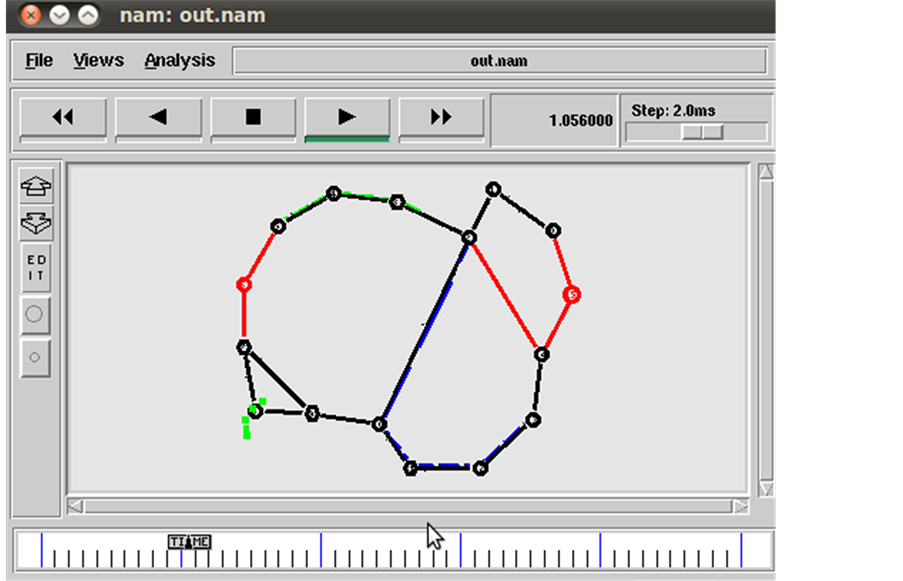
Figure 10. Virtual topology reconfigured.

Figure 11. Fault localization (node recovery).
Table 2. QoS parameters.
Throughput ≤ RW/RTT.
RW, is Received Window.
RTT, is Round Trip Time.
Here throughput using localization algorithm is measured as 50 Mbps.
6.3.2. Jitter
It is the time difference in packet inter-arrival time from source to their destination [15] .

 (a)
(a) (b)
(b) (c)
(c)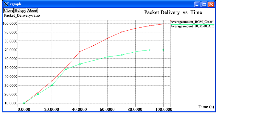 (d)
(d) (e)
(e)
Figure 12. (a) The subplot shows the accuracy of localization algorithm comparing with throughput vs. time; (b) Subplot illustrates the impact of jitter vs. time; (c) The subplot shows the accuracy of localization algorithm comparing with End-End delay vs. time; (d) Subplot illustrates the impact of Packet Delivery vs. time; (e) The subplot shows the accuracy of localization algorithm Number of Transmission vs. time.
Table 3. Failures diagnosed with threshold values.
Request message interval is 10 - 50 seconds.
6.3.3. Packet Delivery Rate vs. Time
The ratio of the number of delivered data packet to the destination. This illustrates the level of delivered data to the destination.
 (5)
(5)
6.3.4. End-to-End Delay
The average time taken by a data packet to arrive in the destination. It also includes the delay caused by route discovery process and the queue in data packet transmission. Only the data packets that successfully delivered to destinations are counted [12] .
 (6)
(6)
6.3.5. Packet Transmission Time
In telecommunication networks, the transmission time, is the amount of time from the beginning until the end of a message transmission. In the case of a digital message, it is the time from the first bit until the last bit of a message has left the transmitting node. The packet transmission time in seconds can be obtained from the packet size in bit and the bit rate in bit/s as:
 (7)
(7)
Using localization algorithm the packets transmitted from source to destinations is 200 packet per second.
6.3.6. Algorithm Accuracy
We simulated many failures from the set of network group. We evaluated the accuracy of algorithm in terms of QoS parameters localized by algorithm. We measure the accuracy of localization algorithm in terms of QoS parameters. The protocol used here is AODV. Initially energy assigned for each node is 100 joules with the consumption of 85 joules with simulation time of 2800 seconds. The algorithm accuracy of localization algorithm based on QoS parameters is greater than 95%.
6.4. Results and Discussion
The Graphs shown in Figure 12 clearly depicts the accuracy of localization algorithm for various QoS parameters.
7. Conclusion
In this paper, it is proposed a new approach, on-demand link state routing for fault localization using risk modelling for IP over WDM optical networks with traffic model [16] . The proposed approach is implemented and computes using Java and simulates using simulator ns-2. The obtained results show that the on-demand link state routing uses route caches to make routing decision, and updates the various types of failures using dynamic database (Table 3). The new localization based modification approach achieves better performance for IP over WDM networks than existing approach in terms of Throughput, jitter, End to end delay and packet delivery. Further, the modification process based on threshold gateway value gives more accurate estimation of QoS parameters, which leads to optimal fault localization of the given topology for the future traffic demand set. Minimum packet loss, load balancing and scheduling are the main point for the quality of service in any networks.
Cite this paper
K. Sashi Rekha,M. Sumathi, (2016) Detection of Link Fault Using Risk Modelling and Improving QOS Parameters in IP/WDM Networks. Circuits and Systems,07,2217-2233. doi: 10.4236/cs.2016.79193
References
- 1. Steinder, M. and Sethi, A.S. (2002) End-to-End Service Failure diagnosis Using Belief Networks. IEEE/IFIP.
- 2. Chao, C.S., Yang, D.L. and Liu, A.C. (1998) An Automated Fault Diagnosis System Using Hierarchical Reasoning and Alarm Correlation. NSC88-2213-E035-008.
- 3. Fang, L.Y., Atlas, A., Chiussi, F. and Kompella, K. (2004) LDP Failure Detection and Recovery. IEEE Communication Magazine, 0163-6804/04/$20.00 ? 2004 IEEE.
- 4. Vanathi, P.T. (2005) Minimizing Congestion in Optical WDM Networks for Dynamic Traffic. 2005 Annual IEEE India Conference, Indicon, 11-13 December 2005, 101-104.
- 5. Johnson, D. and Maltz, D. (1996) Dynamic Source Routing in Ad Hoc Wireless Networks. Springer, US.
- 6. Sumathi, M. (2009) Lightpath Reconfiguration with Traffic Priority Consideration. International Journal of Communication Networks and Distributed Systems, 7, 396-409.
http://dx.doi.org/10.1504/IJCNDS.2009.026877 - 7. Zhang, Y.B., Murata, M., Takagi, H. and Ji, Y.S. (2005) Traffic Based Reconfiguration for Logical Topologies in Large-Scale WDM Optical Networks. Journal of Lightwave Technology, 23, 2854.
- 8. Murthy, C.S.R. and Gurusamy, M. (2001) Wavelength Division Multiplexed Optical Networks: Concepts, Design and Algorithm. Prentice Hall.
- 9. Glenn, R. and Nelakuditi, S. (2012) Handling Multiple Failures in IP Networks through Localized On-Demand Link State Routing. IEEE Transactions on Network and Service Management, 9, 293-305.
- 10. Sue, C.C. (2005) Wavelength Routing with Spare Reconfiguration for All-Optical WDM Networks. Journal of Light Wave Technology, 23.
- 11. Sumathi. M. (2004) Virtual Topology Design for Optical WDM Mesh Networks. ACI-2004.
- 12. Banerjee, D. and Mukherjee, B. (2000) Wave Length-Routed Optical Network: Linear Formulation, Resource Budgeting Tradeoffs and a Reconfiguration Study. Linear Programming Method, 8.
- 13. www.icgst.com
- 14. www.Ijirt.org
- 15. Broch, J., Maltz, D., Johnson, D., Hu, Y.-C. and Jetcheva, J. (2009) A Performance Comparison of Multi-Hop Wireless Ad Hoc Network Routing Protocols. Proc. 4th ACM New York Mobile Computing and network, 85-97.
- 16. Kompella, R.R., Greenberg, J.Y.A. and Soneren, A.C. (2010) Fault Localization via Risk Modelling. IEEE Transactions on Dependable and Secure Computing, 7.
http://dx.doi.org/10.1109/TDSC.2009.37
NOTES

*Corresponding author.