Smart Grid and Renewable Energy
Vol.4 No.2(2013), Article ID:32194,9 pages DOI:10.4236/sgre.2013.42028
Feasibility Study for Self-Sustained Wastewater Treatment Plants—Using Biogas CHP Fuel Cell, Micro-Turbine, PV and Wind Turbine Systems
![]()
Department of Electrical Engineering and Control, Faculty of Engineering and Technology, Arab Academy for Science and Technology, Alexandria, Egypt.
Email: ahmed.helal@staff.aast.edu
Copyright © 2013 Ahmed Helal et al. This is an open access article distributed under the Creative Commons Attribution License, which permits unrestricted use, distribution, and reproduction in any medium, provided the original work is properly cited.
Received January 5th, 2013; revised February 5th, 2013; accepted February 12th, 2013
Keywords: Combined Heat Power; Economic Evaluation; Hybrid Renewable; Waste Water Treatment Plant
ABSTRACT
This paper studies the application of renewable energy sources in wastewater treatment plants to achieve self-sustainability of power. The data of wastewater treatment plant in the rural city of Toukh-EGYPT are presented as a case-study. The primary objective is to provide an entirely renewable standalone power system, which satisfies lowest possible emissions with the minimum lifecycle cost. Mass balance principle is applied on the biodegradable components in the wastewater to evaluate the volume of digester gas that is produced from sludge through anaerobic digestion process. Using digester gas as a fuel lead to study combined-heat-and-power technologies, where fuel cell is selected in order to abide by the low emissions constraint. The study assessed the electrical power obtained from fuel cell and the utilization of the exhausted heat energy for additional electrical power production using a micro-turbine. After covering the major part of load demand, the use of other renewable energy sources was studied. The strength of both solar and wind energy was determined by the case-study location. Hybrid optimization model for electric renewable (HOMER) software was used to simulate the hybrid system composed of combined-heat-and-power units, wind turbines and photovoltaic systems. Simulation results gave the best system configuration and optimum size of each component beside the detailed electrical and cost analysis of the model.
1. Introduction
Energy demands are increasing exponentially resulting into a rapid grow in need of conventional fossil fuels [1]. Such conventional sources are finite and fast depleting, which in turn threatens the balance of future energy demand/generation [2,3]. Renewable energy conversion devices like photovoltaic (PV), micro-turbines (MT), fuel cells (FC) and storage devices are expected to play an important role in future electricity supply and low carbon economy [4,5]. Absence of an electrical network in remote regions and the significantly high connection cost-due to large distances and irregular topography lead often the various organizations to explore alternative solutions [6]. Combining renewable energy to form standalone hybrid systems is considered as one of the most promising ways to handle the electrical requirements of these regions [7]. More and above, other environmental challenges such as greenhouse gas emissions and atmospheric temperature rise spotted the light further on the importance of renewable energy. The idea of the utilization of renewable energy sources (RES) is commonly related with sustainability. A sustainable energy system may be defined as a cost-effective, reliable, and environment friendly energy system that effectively utilizes local resources and networks [8]. For providing a sustainable energy supply, renewable energy sources appear to be one of the most efficient and effective solutions [3,9]. Beside the residential applications, the idea of studying the self-sustainability of power in industrial & service facilities looks very appealing due to their relatively high energy demand, such as wastewater treatment plants (WWTPs). This is because water pollution by nature is an energy intensive process. Also, the operating costs of waste-water treatment facilities in the recent years have increased substantially due to the increases in the unit cost of energy [10]. Using RES whether partially or totally to power WWTPs reduces the operating costs significantly.
Environmental Protection Agency (EPA) concluded that WWTPs with influent flow rate less than 19,000 m3/day didn’t produce enough biogas, through anaerobic digestion process, to make its use as a renewable source for electrical & thermal energies economically feasible [11]. This problem limits the use of biogas—for the plant in-field sustainable power generation—from the point of WWTP scale. Hence, this doesn’t facilitate applying the concept of WWTP self-sustainability using renewable resources in remote and ecological areas unless other intermittent energy sources, such as wind and solar energies, have very strong potential. However, the paper demonstrates that using biogas for power and heat generation might still prove economic even in small-scale WWTP as the criterion primarily depends on the biodegradability of wastewater, not the influent flow rate. Luckily, rural areas, which commonly suffer from low or no electricity service, have strong sewage with high biodegradability which can yield more biogas [12]. The paper evaluates the economics of using biogas with other intermittent energy sources in small-scale rural WWTP to achieve self-sustainability of power. The proposed hybrid power system shall also produce the lowest emissions to match the case of rural ecological areas like oases. The paper uses the WWTP of Toukh-Egypt as a case-study. Section 2 reviews the combined-heat-power technologies working with produced biogas as a fuel. The design uses solid oxide fuel cell (SOFC) coupled with micro-turbine for maximum electrical energy production. Section 3 views the WWTP hourly electrical and thermal load demand to be covered. Section 4 views the necessary information for the software hybrid system modeling like solar & wind energy potentials and prices of the system components. Section 6 presents and discusses the simulation & optimization results.
WWTP of Toukh Center—Qalyobia in Egypt has an average flow of 8000 m³/day. The town of Toukh lies in middle of delta region & intensively surrounded by crops and farms. Being located in rural areas, concentrations of biodegradable components in the wastewater are higher than average concentrations in urban areas. Therefore, the energy recovered from the plant through the digester would be relatively high when compared to urban treatment plants of the same size. The plant uses activatedsludge treatment process. In this process, wastewater flows continuously into an aeration tank (Figure 1) where air is injected to mix the activated sludge with the wastewater and to supply the oxygen needed for the organisms to oxidize the organic compounds. The mixture of activated sludge and wastewater in the aeration tank is called mixed liquor.
The mixed liquor flows from the aeration tank to a secondary clarifier where the activated sludge is settled out.
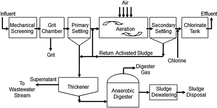
Figure 1. Conventional activated sludge treatment.
Most of the settled sludge is returned to the aeration tank, called return sludge, to maintain the high population of microbes that permits rapid breakdown of the organic compounds. The return sludge is diverted or wasted to the sludge handling system for treatment and disposal [13].
There are two main methods for sludge treatment; aerobic digestion and anaerobic digestion. Aerobic digestion is a suspended-growth biological treatment process based on biological theories similar to those of the extended aeration modification of the activated sludge process [14]. Anaerobic digestion (AD) plays an important role for its abilities to further transform organic matter into biogas (contains 65% - 70% methane by volume, 25% - 30% CO2, and small amounts of N2, H2, H2S, water vapor & other gases). The biogas, or anaerobic digester gas (ADG), can be utilized to produce energy using combined heatpower (CHP) technology [15]. The plant uses the most common scenario in sludge treatment in Egypt where the thickened sludge is directly pumped to natural dewatering without involving the digestion process [16]. Within here, the presence of anaerobic digester is assumed for sludge treatment. The production of digester gas has been estimated given the sludge daily mass, volume and concentration of biodegradable components in the raw sewage and sludge.
2. Energy Recovery in WWTP
Digester gas resulting from the anaerobic digester used in WWTP can be used to power an engine-generator SET to generate electricity, and the jacket water from the internal combustion engine can be used for digester or building heating [17]. New emerging technologies compete the combustion engines offering better emissions reduction such as fuel cell and micro-turbine. Co-generation of power and heat by these technologies is referred as combined heat-power (CHP).
Many researches have been made on the comparison between the CHP technologies over the small-scale applications. Operation, components, applications, costs, advantages & disadvantages of CHP technologies can be found in [10-26]. Selection of the technology will depend greatly on the nature of application. If cost & emissions are a major concern, reciprocating engines present lowest cost but highest emissions. FC systems have lowest emissions but highest cost. Micro-turbines offer a balance between the two factors. Startup time, part load response & efficiency also could be key performance factors according to the application type to be base load, peak shaving or emergency. Noise & size are also important factors for residential applications. Emissions reduction is always a major concern in agriculture & rural areas. Being one of the research goals, emission reduction will turn the CHP selection for the favor of fuel cells.
2.1. Selection of Fuel Cell Type
Solid Oxide Fuel Cells (SOFC) belongs to the group of high-temperature fuel cells. They are operated at temperature up to 1000˚C and are of high interest because of their specific properties, especially the fuel utilization: they are able to work with a great variety of fuels (gaseous hydrogen or hydrocarbons like gasoline, diesel, kerosene, heavy oil, natural gas, or even biogas) while needing only a relatively low demand for cleaning, in particular concerning sulphur, and reforming of these fuels [27]. Amongst fuel cells for biogas conversion, the high temperature solid oxide fuel cell (SOFC) type is especially suited because of the capability of thermally integrated biogas reforming and because of manageable tolerance against fuel contaminants [28].
Due to their high operating temperature, SOFCs can convert hydrocarbons into hydrogen internally, showing global electrical efficiencies approximately of 46% even when fed by methane. SOFCs are also considered as one of the most promising candidate for a future high efficiency decentralized energy conversion model. Due to their high operating temperature and modularity, SOFCs can be easily integrated into cogeneration power plants, producing electricity, heat and cooling energy, when combined with absorption chillers [29].
2.2. Fuel Cell Model Characteristics
The fuel cell model selected for the case study is the one introduced in [30] for utilization of energy recovered from a wastewater treatment plant & using digester gas as a fuel. This study viewed the general & inside characteristic of the model fuel cell including its behavior under varying conditions. The characteristics for the fuel cell used in the study at operating point are shown in Table 1.
The estimated volume of digester gas produced by the anaerobic digester is 54.9 m³/hr. Only 44.6 m³/hr of the digester gas is assumed to be used. Having spare volume allows isolating the fluctuation of ADG production from
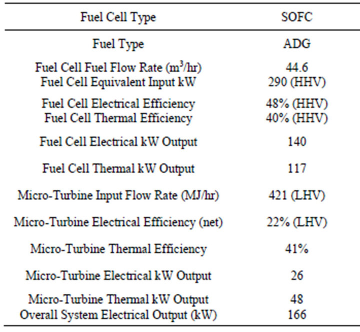
Table 1. Fuel cell and micro-turbine characteristics.
the fuel cell input system. Hence, guarantees continuous availability of gas and sustainable power generation.
As listed in Table 1, the net thermal power produced from the fuel cell is approximately 117 kW. The only heat load available in the plant is the digester heat load. Because of the warm climate in Egypt and the current limited purposes of thermal energy, excess thermal energy would be usually diffused to the atmosphere [31]. However, coupling a small size micro-turbine to the fuel cell can convert the excess thermal power to usable electrical power. Thus, it’ll cover additional portion of plant electrical loads.
2.3. Micro-Turbines
Micro gas turbines are small gas turbines belonging to the group of turbo machines up to an electric power output of 300 kW. In order to raise the electrical output micro gas turbines are equipped with a recuperator (heat/ heat exchanger). They are also equipped with a regular heat exchanger in order to use the waste heat from the exhaust gases [18]. Micro-turbine will be used for producing power from heat exhaust of the fuel cell forming what is called FC-MT hybrid model. This hybrid system offers a solution to two important problems, the low efficiency and relatively high emissions of small gas turbines, and the high cost of small fuel cell power plants [32]. MT has a smaller volume and weight but also a lower efficiency and larger emissions than a normal gas turbine. Therefore, a MT working as a stand-alone device generates not so much benefit. A fuel cell is a clean energy generator and has a considerably higher and constant efficiency even at different operating temperatures, but its volume is still extremely large [33].
The integration of FC-MT hybrid model can be done by two methods, atmospheric pressure system and pressurized system. The main advantage of atmospheric pressure system that it allows is the selection of the MGT pressure independently of the cell pressure [28]. Meanwhile, some basic studies have concluded that a pressured system may have higher system efficiency over an ambient pressure system from a thermodynamic point of view if equivalent design parameters are assumed [28]. In the pressurized system, used in the design, the fuel cell operates at an elevated pressure with the micro-turbine (Figure 2). Under steady state, the micro-turbine compressor is used to pressurize the air entering the fuel cell. Chemical reactions take place in the fuel cell producing both electricity & heat. With both fuel compressed by a fuel pump & the air by the compressor, the hot pressurized exhaust leaves the SOFC and goes directly to the expander section of the turbine, which drives both the compressor and the generator. The exhaust from the turbine is used through heat exchanger to heat air & fuel prior to entering the fuel cell [34].
2.4. SOFC-MT Hybrid Model
The output of the fuel cell to be directed to the microturbine expander is 117 kW (421 MJ/hr) which approximately equals input power required to run a 26 kW micro-turbine under full load. The characteristics of the micro-turbine used in the model are listed in Table 1. As a result, the SOFC-MT system will deliver 140 kW from the fuel cell & 26 kW from the micro-turbine. This yield overall electrical power output of 166 kW and 32.7 kW of useful thermal power leaving heat exchanger.
3. Plant Load Study
3.1. Electrical Load
Wastewater treatment plants are often the largest consumer of energy within local city and community government loads [35]. Energy requirements in waste-water treatment are mainly for pumping, primary treatment, secondary treatment, space heating, and sludge heating and disposal [10]. Plant loads according to its design & installation were grouped, and distributed throughout their working hours to form the load profile as in Figure 3. The plant has a peak load of 240 kW & minimum load of 146 kW. Diversity factor is relatively low compared to residential loads. The reason is that the aeration system in WWTP, which represents a large percentage of total plant power demand, operates 24 hours per day. Other small loads such as mechanical screen & ventilators operate occasionally; causing the respectively small deviation round the average. Maximum power deviation is 27% with 201 kW average power. Based on this load profile and the results obtained in Section 2 about the CHP output power, the load coverage percentage using the biogas energy is 69% of the WWTP peak load.
3.2. Thermal Load
Space heating is not needed in the system due to the warm Egyptian climate. Anaerobic digestion process requires heat for maintaining a stable operating tempera

Figure 2. Pressurized hybrid FC-MT.
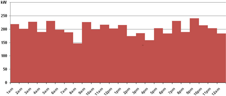
Figure 3. Plant hourly electrical load profile.
ture of the digester. This is important because the bacteria, especially the methane formers, are sensitive to temperature changes [17]. Most anaerobic digesters utilize conventional gas-fired boilers coupled to a heat exchanger in order to transfer the heat of combustion to the digested sludge [36]. The CHP system offers ready thermal power for the digester without the need for gas-fired boilers. Detailed calculations have been made to check if the digester heat load will be met by the thermal power output from the micro-turbine in FC-MT hybrid system. The operating temperature of the digester is assumed to be 35˚C which is optimal for the digestion process [10]. The heat load is sum of two quantities. The first is the heat required to raise the temperature of the input sludge stream to the operating temperature. This heat yields 9.975 kW assuming 30˚C difference between ambient and entering sludge temperatures. The second is the heat required to balance the radiation and other heat losses through the digester walls [17]. This amount of heat yields 8.6 kW. Thus, plant digester heat load is about 18.5 kW and completely covered by useful heat from micro-turbine exhaust. Ref. [17] has detailed the formula used to calculate the digester heat load.
4. System Modeling
There is still a part of the WWTP electrical load demand which needs to be covered. Other RES (Solar and wind energy) are utilized to cover this part as shown in Figure 4. The software tool used for the micro-power system optimization HOMER allows modeling energy resources in the site together with the energy conversion systems and hence calculates optimum configuration and size of each component.
4.1. Resources
There are three modeled renewable energy sources in the program. First is biogas from plant waste. Energy potential of the other two (solar & wind) are determined by the solar radiation & wind speed respectively. The annual average radiation of the site per unit area of horizontal surface is 5.52 kWh/m2/day. Solar energy Data are given
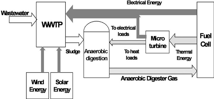
Figure 4. Energy flow diagram for the hybrid system.
in Figure 5 where clearness index, shown, is the measure of the clearness of the atmosphere. The plant site average wind speed, shown in Figure 6 is 4.75 m/s.
4.2. Solid Oxide Fuel Cell Modeling
The capital cost for the 100 - 250 kW SOFC was estimated by EEA (energy & environmental analysis) to be 2850 $/kW as package cost & 3620 $/kW as total installed cost while O&M costs were estimated to be 0.024 $/kWh [22]. Ref. [37] indicated that capital cost of solid oxide fuel cell is about 3000 US $/kW with estimates for the reduction of the costs to 500 US $/kW in the near future, current operation and maintenance (O&M) cost of SOFC is about 0.025 US $/kWh and could be reduced to around 0.01 US $/kWh in future. In studying the fuel cell operation on digester gas [38], key assumptions were made for the fuel cell to have entry level price of 3000 $/kW and O&M cost of 0.015 $/kWh. For the lifetime, the simplicity of the SOFC design and its complete absence of liquids mean that the SOFC fuel cell should have an extremely long operating life. Units have been tested for 60,000 hours without failure and operating lives of 20 years or more can be expected [39]. Replacement cost in all system’s components is assumed to be 60% of its relevant capital cost.
4.3. Micro-Turbine Modeling
EPA showed that the micro-turbine as a CHP unit has capital installed cost range of 2400 to 3000 $/kW and O&M cost of 0.012 to 0.025 $/kWh [22]. Package cost without installation was stated to range from 800 to 1650
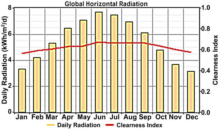
Figure 5. Solar energy resource data.
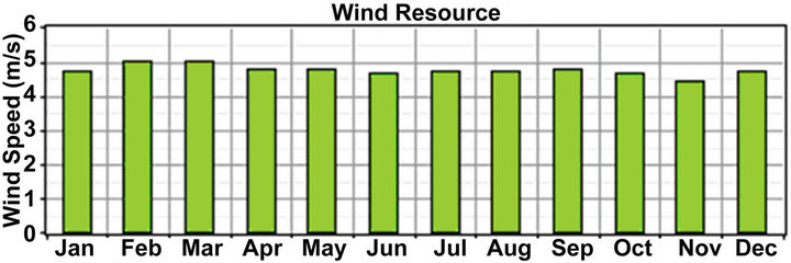
Figure 6. Wind energy resource data.
$/kW & overhaul frequency is from 30,000 to 50,000 hours [21]. Price for commercially available 30 kW micro-turbine in 2007 was 1290 $/kW as package cost & 2970 $/kW for total installed cost [34]. Ref. [23] showed a close price by energy nexus group for the same size (30 kW micro-turbine); that is 2516 $/kW. Price is given by National Renewable Energy Laboratory (NREL) as 2263 $/kW for the total installed cost [22]. FC and MT of hybrid FC-MT system are individually modeled in the software as it doesn’t have a single component for FCMT integration. However, having a constant input power from the FC-MT system makes this modeling valid.
4.4. Wind Turbine System Modeling
Whereas the rated power of new wind machines has increased year by year, the corresponding capital cost per kW dropped [40]. Ref. [39] showed that the current installation costs for an onshore wind farm at between EUR700/ kW and EUR1000/kW. Smaller wind farm or residential scale turbines cost less overall, but are more expensive per kilowatt of energy producing capacity. Wind turbines of few kilowatts cost roughly $3000 to $5000 per kilowatt of capacity. Medium size wind turbines system as the one modeled would cost typically 2400 $/kW. O&M cost is entered as 30 $/kW [24]. In order to obtain most accurate results, market prices are entered in parallel with technical specs. The modeled wind turbine system is the commercial model FD10 by FSW. The specifications of the system are entered to HOMER along with its market cost.
4.5. Other Components Modeling
Cost of PV system here is based on commercial market in 2012 for medium size systems (100 - 200 kW). Collecting data considers also both technical data of the system together with its price to ensure accurate results.
The rest of components, to complete the hybrid model operation, are converters & battery bank. The inverter price is 650 $/kW in average [40,41] which is typically conformed to commercial market price. For battery system, commercial cost is according to the type of battery selected in the program. Because the output of PV & wind turbine system is variable, the software will first experience different connection topologies to determine which one of them should be connected on AC or DC side. Discussion is made for the optimum system size. The optimum system is defined as the system combination which satisfies the user defined constraints at the lowest life cycle cost or net present cost (NPC).
5. Results and Discussion
The optimization results are listed in Table 2. Each scenario provided four categories of optimized systems. Each

Table 2. Optimization results.
category represents unique set of subcomponents combination. The viewed result in every category is the optimum result of this category; which states the size of each component of the system that grants the lowest lifecycle cost. Optimum category in each scenario uses all the components (PV, WTS, FC and MT). The other three categories in each scenario showed possible elimination of MT or PV or WTS at higher cost. Table 2 showed that the best connection topology is when coupling both PV & WTS systems to the DC bus (Figure 7) through the first category (DC-DC1) with NPC of 3,682,842$. PV system is best coupled to DC bus in sites with very poor wind speeds (scenarios DC-AC2 and DC-DC2 where WTS is not used) and same goes for WTS (scenarios DC-DC3 and AC-DC2) in case very poor solar radiation.
5.1. FC-MT Hybrid System Results
Figure 8 shows the cash flow summary. SOFC has the biggest cash flow over project lifetime with 38% share of NPC. However, it has bigger share in energy generation (61% of average yearly production). Micro-turbine generation share is 9% compared to 11% by PV system. Meanwhile, NPC of MT is only 44% of PV system NPC (Figure 9). This shows the economic effectiveness of coupling MT to FC and also shows the advantage of utilizing energy recovered from plant waste over the utilization of other supplementary RES.
5.2. WTS & PV System
Results for photovoltaic & wind turbine systems are summarized in Table 3. Although PV system everywhere has low capacity factor as it shuts down in the night, poor wind speed in the site caused the WTS to have approximately same capacity factor. In addition, the weak wind resource caused the effective NPC/kW of turbine very close to the NPC/kW for the PV system (17,764 $/kW for WTS and 16,040 $/kW for PV).
5.3. Battery Storage System
Battery storage system comes in the 2nd order as the highest NPC after the fuel cell. This is because the number of batteries installed is relatively high. This high number was required to match the variable nature of solar & wind energy. The reason for installing this high quantity of batteries (90 strings, 48 volts) as shown in Figure 10 that the wind speed sometimes stays below the cut-in speed of the turbine resulting zero power output of the WTS system. If this occurrence takes place in the night while PV system is shut down, it falls only to the battery system to cover the electrical demand with the SOFCMT hybrid system. Battery system can be further minimized if turbine cut-in speed is lower.
6. Conclusion
The paper presented the economic evaluation and unit sizing for a standalone micro-power system. The system serves a wastewater treatment plant using energy sources which are entirely renewable. The paper uses the data of Toukh WWTP as a case study. First, small scale CHP technologies are investigated for power production from biogas produced by anaerobic digestion process. FC has been selected as it grants the lowest emissions among other CHP technologies. The system generated power-toheat ratio is maximized by coupling MT with FC exhaust. The FC-MT system grants 166 kW and 32.7 kW of the electrical and thermal power respectively. The Softwaresimulation and optimization results used all CHP capac-
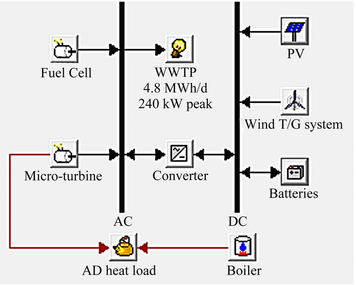
Figure 7. Optimum system configuration.
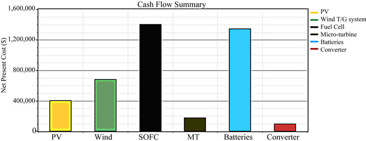
Figure 8. Cash flow summary.

Figure 9. Average generation share.
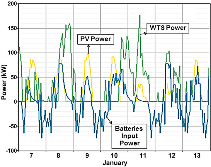
Figure 10. Relation between batteries & intermittent RES.
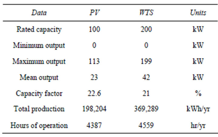
Table 3. PV and WTS output.
ity in addition to 200 kW wind turbine system, 100 kW PV system, 720 batteries & 80 kW converter to achieve self-sustainability of power. Results showed that the best connection topology is connecting both PV & wind turbine systems to the DC bus. The use of biogas and combined-heat-power technologies proves to be more economical than solar & wind energy equipment. Battery storage system formed expensive part of the standalone system as, wind power may go lower at night while PV system is shut down; making the sustainability in these time steps totally dependent on only CHP & battery systems.
REFERENCES
- S. Rehman, I. M. El-Amin, F. Ahmad, S. M. Shaahid, A. M. Al-Shehri, J. M. Bakhashwain, et al., “Feasibility study of Hybrid Retrofits to an Isolated Off-Grid Diesel Power Plant,” Renewable and Sustainable Energy Reviews, Vol. 11, No. 4, 2007, pp. 635-653. doi:10.1016/j.rser.2005.05.003
- M. Ball, M. Wietschel and O. Rentz, “Integration of a Hydrogen Economy into the German Energy System: An Optimizing Modeling Approach,” International Journal of Hydrogen Energy, Vol. 32, No. 10-11, 2007, pp. 1355- 1368. doi:10.1016/j.ijhydene.2006.10.016
- S. M. Shaahid and M. A. Elhadidy, “Technical and Economic Assessment of Grid-Independent Hybrid Photovoltaic-Diesel-Battery Power Systems for Commercial Loads in Desert Environments,” Renewable and Sustainable Energy Reviews, Vol. 11, No. 8, 2007, pp. 1794- 1810. doi:10.1016/j.rser.2006.03.001
- R. U. Ayres, H. Turton and T. Casten, “Energy Efficiency, Sustainability and Economic Growth,” Energy, Vol. 32, No. 5, 2007, pp. 634-648. doi:10.1016/j.energy.2006.06.005
- E. R. Sanseverino, M. L. Di Silvestre, M. G. Ippolito, A. De Paola and G. L. Re, “An Execution, Monitoring and Replanning Approach for Optimal Energy Management in Micro Grids,” Energy, Vol. 36, No. 5, 2011, pp. 3429- 3436. doi:10.1016/j.energy.2011.03.047
- O. Erdinc and M. Uzunoglu, “Optimum Design of Hybrid Renewable Energy Systems: Overview of Different Approaches,” Renewable and Sustainable Energy Reviews, Vol. 16, No. 3, 2012, pp. 1412-1425. doi:10.1016/j.rser.2011.11.011
- P. Yilmaz, M. H. Hocaoglu and A. E. S. Konukman, “A Pre-Feasibility Case Study on Integrated Resource Planning Including Renewables,” Energy Policy, Vol. 36, No. 3, 2008, pp. 1223-1232. doi:10.1016/j.enpol.2007.12.007
- A. Hepbasli, “A Key Review on Exergetic Analysis and Assessment of Renewable Energy Resources for a Sustainable Future,” Renewable and Sustainable Energy Reviews, Vol. 12, No. 3, 2008, pp. 593-661. doi:10.1016/j.rser.2006.10.001
- A. Kornelakis, “Multiobjective Particle Swarm Optimization for the Optimal Design of Photovoltaic Grid-Connected Systems,” Solar Energy, Vol. 84, No. 12, 2010, pp. 2022-2033. doi:10.1016/j.solener.2010.10.001
- S. A. Tassou, “Energy Conservation and Resource Utilization in Waste-Water Treatment Plants,” Applied Energy, Vol. 30, 1988, pp. 113-129. doi:10.1016/0306-2619(88)90008-6
- Eastern Research Group, Inc. (ERG) and Resource Dynamics Corporation, “Opportunities for Combined Heat and Power at Wastewater Treatment Facilities: Market Analysis and Lessons from the Field,” US Environmental Protection Agency (EPA) Combined Heat and Power Partnership (CHPP), 2011. http://www.epa.gov/CHP/documents/wwtf_opportunities.pdf
- T. A. Elmitwall, A. Al-Sarawey, M. F. El-Sherbiny, G. Zeeman and G. Lettinga, “Anaerobic Biodegradability and Treatment of Egyptian Domestic Sewage,” 5th IWA Conference in Small Water and Wastewater Treatment Systems, Istanbul, 24-26 September 2002.
- M. L. Davis, “Water and Wastewater Engineering-Design Principles & Practice,” The McGraw-Hill Companies, Inc., New York, 2010.
- Water Environment Federation, “Design of Municipal Wastewater Treatment Plants,” 5th Edition, McGraw-Hill Professional, New York, 2010.
- A. Lise, J. Baeyans, J. Degreve and R. Dewil, “Principles and Potential of the Anaerobic Digestion of Waste-Activated Sludge,” Progress in Energy and Combustion Science, Vol. 34, No. 6, 2008, pp. 755-781. doi:10.1016/j.pecs.2008.06.002
- M. Ghazy, T. Dockhorn and N. Dichtl, “Sewage Sludge Management in Egypt: Current Status and Perspectives towards a Sustainable Agricultural Use,” World Academy of Science, Engineering and Technology, Vol. 57, 2009, p. 492.
- T. George, F. L. Burton and H. D. Stensel, “Wastewater Engineering. Treatment & Reuse,” 4th Edition, Metcalf & Eddy, Inc., New York, 2003.
- G. R. Simader, R. Krawinkler and G. Trnka, “Micro CHP systems: State-of-the-Art,” Österreichische Energieagentur, Austrian Energy Agency, 2006.
- Energy and Environmental Analysis, “Technology Characterization: Fuel Cell,” Environmental Protection Agency, Combined Heat and Power Partnership, 2008. http://www.epa.gov/chp/documents/catalog_chptech_fuel_cells.pdf
- C. Soares, “Microturbines-Applications for Distributed Energy Systems,” Elsevier Inc., Amsterdam, 2007.
- J. R. Wiser, J. W. Schettler and J. L. Willis, “Evaluation of Combined Heat and Power Technologies for Wastewater Treatment Facilities,” US Environmental Protection Agency, 2010. http://www.brownandCaldwell.com.
- Energy and Environmental Analysis, “CHP Technologies,” Environmental Protection Agency, 2008. http://www.epa.gov/chp/documents/catalog_chptech_full.pdf
- National Renewable Energy Laboratory, “Gas-Fired Distributed Energy Resource Technology Characterizations,” Report NREL/TP-620-34783, 2003.
- A. Bauen, D. Hart and A. Chase, “Fuel Cells for Distributed Generation in Developing Countries—An Analysis,” International Journal of Hydrogen Energy, Vol. 28, No. 7, 2003, pp. 695-701. doi:10.1016/S0360-3199(02)00248-3
- S. Mekhilef, R. Saidur and A. Safari, “Comparative Study of Different Fuel Cell Technologies,” Renewable and Sustainable Energy Reviews, Vol. 16, No. 1, 2012, pp. 981- 989. doi:10.1016/j.rser.2011.09.020
- K. Alanne and A. Saari, “Sustainable Small-Scale CHP Technologies for Buildings: The Basis for Multi-Perspective Decision-Making,” Renewable and Sustainable Energy Reviews, Vol. 8, No. 5, 2004, pp. 401-431. doi:10.1016/j.rser.2003.12.005
- P. Viebahn, R. Gerboni, M. Pehnt and E. Lavagno, “Final Report on Technical Data, Costs and Life Cycle Inventories of FCs,” New Energy Externalities Developments for Sustainabiliy (NEED), 2008. http://www.needs-project.org/RS1a/RS1a%20D9.2%20Final%20report%20on%20fuel%20cells.pdf
- J. Van Herle, Y. Membrez and O. Bucheli, “Biogas as a Fuel Source for Solid Oxide Fuel Cell Cogenerators,” Journal of Power Sources, Vol. 127, No. 1-2, 2000, pp. 300-312. doi:10.1016/j.jpowsour.2003.09.027
- F. Calise, “Design of a Hybrid Polygeneration System with Solar Collectors and a Solid Oxide Fuel Cell: Dynamic Simulation and Economic Assessment,” International Journal of Hydrogen Energy, Vol. 36, No. 10, 2011, pp. 6128-6150. doi:10.1016/j.ijhydene.2011.02.057
- A. Liu and Y. Weng, “Performance Analysis of a Pressurized Molten Carbonate Fuel Cell/Micro-Gas Turbine Hybrid System,” Journal of Power Sources, Vol. 195, No. 1, 2010, pp. 204-213. doi:10.1016/j.jpowsour.2009.07.024
- M. R. Ghazy, T. Dockhorn and N. Dichtl, “Economic and Environmental Assessment of Sewage Sludge Treatment Processes Application in Egypt,” International Water Technology Journal, Vol. 1, No. 2, 2011.
- F. Jurado, “Study of Molten Carbonate Fuel Cell—Microturbinehybrid Power Cycles,” Journal of Power Sources, Vol. 111, No. 1, 2002, pp. 121-129. doi:10.1016/S0378-7753(02)00340-3
- D. Bohn, “Micro Gas Turbine and Fuel Cell—A Hybrid Energy Conversion System with High Potential,” In: Micro Gas Turbines, 2005, pp. 13-1-13-46. http://www.rto.nato.int/abstracts.asp
- R. A. George and N. F. Bessette, “Reducing the Manufacturing Cost of Tubular SOFC Technology,” Journal of Power Sources, Vol. 71, No. 1-2, 1998, pp. 131-137.
- “Energy Conservation in Wastewater Treatment Facilities Manual of Practice,” Water Environment Federation, Alexandria, 1997, pp. 1-142. doi:10.1016/S0378-7753(97)02735-3
- J. Nouri, et al., “Energy Recovery from Wastewater Treatment Plant,” Pakistan Journal of Biological Sciences, Vol. 9, No. 1, 2006, pp. 3-6. doi:10.3923/pjbs.2006.3.6
- M. Ameri and M. J. Heidari, “The Application of Solid Oxide Fuel Cell for Power Generation in Iran: Feasibility and Cost Analysis,” The 2nd Joint International Conference on Sustainable Energy and Environment (SEE 2006), Bangkok, 21-23 November 2006.
- R. J. Spiegel, et al, “Fuel Cell Operation on Anaerobic Digester Gas: Conceptual Design and Assessment,” Waste Management, Vol. 19, No. 6, 1999, pp. 389-399. doi:10.1016/S0956-053X(99)00197-X
- P. Breeze, “Power Generation Technologies,” Newnes, New South Wales, 2005.
- G. M. Masters, “Renewable and Efficient Electric Power Systems,” John Wiley & Sons, Inc., New York, 2004. doi:10.1002/0471668826
- Al-Badi, et al, “Economic Perspective of PV Electricity in Oman,” Journal of Energy, Vol. 36, No. 1, 2011, pp. 226-232. doi:10.1016/j.energy.2010.10.047