Advances in Remote Sensing
Vol. 2 No. 2 (2013) , Article ID: 33180 , 9 pages DOI:10.4236/ars.2013.22018
Accuracy Analysis on the Automatic Registration of Multi-Source Remote Sensing Images Based on the Software of ERDAS Imagine
1College of Geoscience and Surveying Engineering, China University of Mining and Technology, Beijing, China
2The Geotechnical Institute of Beijing AeroSpace, Beijing, China
Email: yuandb@cumtb.edu.cn
Copyright © 2013 Debao Yuan et al. This is an open access article distributed under the Creative Commons Attribution License, which permits unrestricted use, distribution, and reproduction in any medium, provided the original work is properly cited.
Received January 31, 2013; revised March 1, 2013; accepted March 10, 2013
Keywords: Multi-Source Remote Sensing Images; Automatic Registration; Image Autosync; Registration Accuracy
ABSTRACT
The automatic registration of multi-source remote sensing images (RSI) is a research hotspot of remote sensing image preprocessing currently. A special automatic image registration module named the Image Autosync has been embedded into the ERDAS IMAGINE software of version 9.0 and above. The registration accuracies of the module verified for the remote sensing images obtained from different platforms or their different spatial resolution. Four tested registration experiments are discussed in this article to analyze the accuracy differences based on the remote sensing data which have different spatial resolution. The impact factors inducing the differences of registration accuracy are also analyzed.
1. Introduction
With the development of remote sensing technology, more and more remote sensing images are being produced. These images are obtained in different time phases, resolutions, wave range and by different sensors. The remote sensing and artificial intelligent technologies make the fusing and comprehensive utilization of different-source remote sensing images possible. Nevertheless, one of the key problems is how to realize the images match automatically. Some institutions and scholars, in China and abroad, have made abundant research on remote sensing image automatic registration. Some researchers created the relevant algorithm on different types of data design. In 1998, Zuxun Zhang et al. put forward a rapid full-automatic method for the registration of remote sensing images with different resolutions and from different sensors. The main content of the method in this article is to use multi-stage image probability relaxation integrated matching technology. The high resolution image was taken as a reference image, and the reporter also makes full use of high-resolution-image information to improve the accuracy of registration. However, this method requires the spectral characteristics of the selected images shouldn’t be in much difference. Le Yu et al. [1] adopted the coarse-to-fine method to register the remote sensing images. The method is described here. Firstly, the Sift operator was used to extract feature points of images for coarse registration. Secondly, the method of adaptive-feature extraction based on Harris operator was then adopted to make the feature points distribute uniformity. Finally, the TIN etc., multiple technologies were used to realize the image fine registration [2,3]. However, this method is directly based on the maximum residual information when making the coarse deletion. The method of deleting coarse has been proven not robust sufficiently. The ERDAS IMAGINE software has also been made research in multi-source remote sensing image registration. In version 9.0 and above version, an extra special remote sensing Image automatic registration module—Image Autosync module, was added in. This module could realize the automatic registration of the multi-source remote sensing images. The registration efficiency and accuracy are greatly improved. Nevertheless, in this module, the accuracy of remote sensing image registration is different for images with different resolution and in different platforms. The lower the resolution, the lower the registration accuracy is.
The registration test and precision analysis of remote sensing images with different time, different regions and different resolution are reported in this article based on the previous research. The Image Autosync module of Image Autosync is validated in the registration of remote sensing data although there are still some multiple problems in Accuracy differences. The brief analysis of the causes of problems is given.
2. Multi-Source Remote Sensing Image Registration
Multi-source remote sensing image registration is superimposing [4] of two or more remote sensing images which have different wave band, different time phase, different angles of view or different sensor within the same area or the same target. The main purpose of image registration is to achieve two or more remote sensing images with the geometric position consistency through decreasing or eliminating the geometric deformation caused by the imaging-condition differences between preregistration images and the reference images. Multisource remote sensing image automatic registration is a key step of remote sensing image preprocessing, and is also the basis to realize remote sensing image analysis of the same target or area, comprehensive and comparative processing. It plays a quite important role in processing the remote sensing image.
3. Image Autosync Module
Image Autosync is an added module in the ERDAS IMAGINE 9.0, which provides an automatic image registration tools to ensure the users in various technical levels to complete professional registration work easily. The module mainly includes image edge matching and geographic reference image registration functions. The first workflow is to input two or more images with potential difference, such as HJ images and TM images. Thousands of homonymy points in their overlap region are produced to obtain high-precision registration of remote sensing image. This method can not only change the existed registration accuracy in the geographic- reference image, but also realize rapid registration from the original image to image based on geographic reference. The second workflow is the edge matching, which apply the partial model to the overlap part of the image. This submodule Autosync Workstation in the Image Autosync module is mainly used to complete registration of remote sensing image with different sensors, different time phases, different resolutions, and make a detailed contrastive analysis with their registration accuracy.
3.1. Autosync Workstation Automatic-Registration Theory
In the ERDAS IMAGINE 9.0 and above versions, the automatic-registration module with the tool APM (Automatic Point Measurement) to automatically match the control point. In Image Autosync, APM is a software tool to automatically identify the control points consistent when input two different grid images—input image and the reference image. The basic theory of APM automatically matching the control point is that use pyramid data structure to match level by level. When APM began to run, firstly, it establishes respectively a 3 × 3 image pyramid data structure for the input image and the reference image, which is a group of image sequence generated from low to high resolution. Began to match with the lowest level resolution, the APM will then find the matching point and mapping it to the search area of the last layer, and improve a layer of resolution of the two images, match in the search area, improve the resolution until in accordance with the original image resolution. The matching points of the two images are obtained [5].
3.2. Autosync Workstation Registration Process
It’s very convenient for ERDAS IMAGINE to realize the automatic registration. The user only need to input the pre-registration IMAGE and the reference IMAGE, and choose feature points extracted options, IMAGE corrected option and IMAGE resampling options in different options, and finally we can get the images which splice of reference IMAGE after registration and pre-registration IMAGE. The concrete realization steps as shown in Figure 1.
Under the working environment of Autosync Workstation, a reference image and one or more pre-registration images are needed to be input. In order to achieve higher registration accuracy, the overlap of the images should be at least 20% [6]. As the reference image and pre-registration images sometimes come from different sensors, different time phases and different resolutions, the shear in advance may needs, so that the two images could be overlapped more.
After inputting the reference image and pre-registration image, the parameters of APM are required to be set. In APM, the option of advanced Point Matching Strategy —Use Manual TiePoints for Initial Connection between Images, and its default is not ticked. In order to ensure the accuracy of registration, here, this option is chosen, and four control points in the four corner areas of the image are chosen. In the APM parameter of senior control point matching strategy, there is a Minimum Point Match Quality. The parameter value ranges from 0.60 to 0.99. The smaller this value, the more the matching points will be, but the more the wrong matching points are. On the contrary, the higher the value the less the matching points are, but the less the wrong matching points are. The value is set according to the specific conditions of the two images. Typically, the value is a few bigger in plain region of the image, and the value is
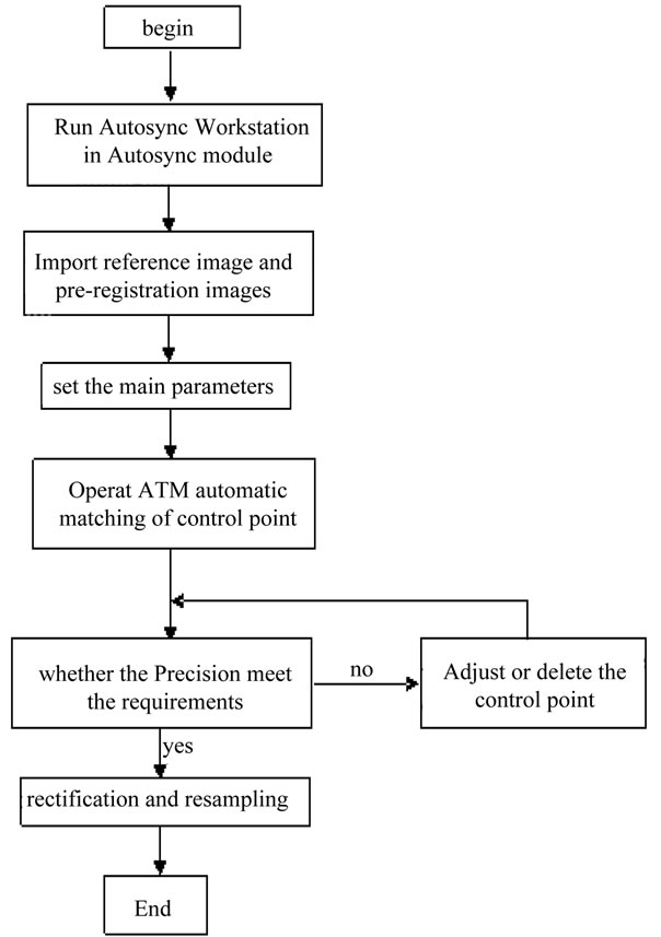
Figure 1. Registration process.
smaller in mountainous area of the image or when image quality is poor [7].
3.3. Accuracy Control and Resampling
Image registration accuracy is usually measured by RMS error (root mean square). The following is calculation formula:
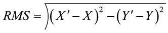 (1)
(1)
X and Y represents the original coordinates in Formula (1), and  and
and  represents coordinates after conversion. The total RMS error is determined by the residual. Residual is the distance between the original coordinate and inverse transform coordinates on one direction. Residual X is the distance between original X coordinates and conversion
  coordinates, so as residual Y, total RMS error shows as follow:
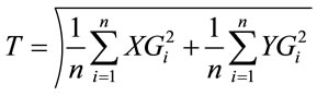 (2)
(2)
In Formula (2), T represents total RMS error, n represents the number of GCP point, XGi represents the X residual of GCPi, YGi represents the Y residual of GCPi.
Through the GCP tools in Autosync Workstation, the RMS error and total RMS error of GCP points can be seen. If the RMS error doesn’t reach the requirements of precision, (some) low quality control points will be deleted to reach the accuracy [8].
After the RMS reached the accuracy, the pre-registration image will be matched and sampled. Due to more points extracted automatically, usually, the Polynomial (Polynomial transformation) is used to realize registration. In this paper, three Polynomial transformations were chosen [9]. In the resampling, bilinear interpolation method is selected. The combination of the above two transformation mode can not only reach the registration accuracy requirement also can improve the speed of registration. After the resampling, we can analyze the stability of ERDAS IMAGINE automatic registration for multi-source remote sensing data registration through the local amplification of prominent feature and total RMS [10].
4. Image Autosync Registration Test
In order to analyze the impact factors to precision for the multi-source sensor image registration, the data and the way of combinations in the test are as follows: 30 m resolution, HJ data of Jiangsu and HJ data; 30 m resolution, TM data of Tibet and TM data; 30 m resolution, HJ data of Jiangsu and TM data and 0.41 m resolution Geoeye data of Hainan area and 0.1 m resolution unmanned aerial vehicle (uav) data. This paper uses the above data to realize the automatic Image registration through the ERDAS IMAGINE, and analyze the accuracy of registration results from the vision and the root mean square.
4.1. Automatic Registration Test
In the four tests, the cubic polynomial is used for registration and the method of bilinear interpolation is used for image resampling.
Test 1: HJ data and HJ data registration test
Loading data and automaticlly extracting rear interface of control point which is shown in Figure 2.
Accuracy analysis
Some typical points were selected from the report of ERDAS automatic registration, shown in Table 1. This table includes the minimum and the maximum error of the registration points and maximum matched and minimum matched point.
1) Visual effect analysis. As shown in Figure 3, it is the local enlarged view after two HJ star image spliced.
2) The RMS error analysis. From self-generated report of ERDAS, the root mean square error is 1.182 after HJ star image registration.
Test 2: TM data and TM data registration test
Loading data and the distribution of feature point after
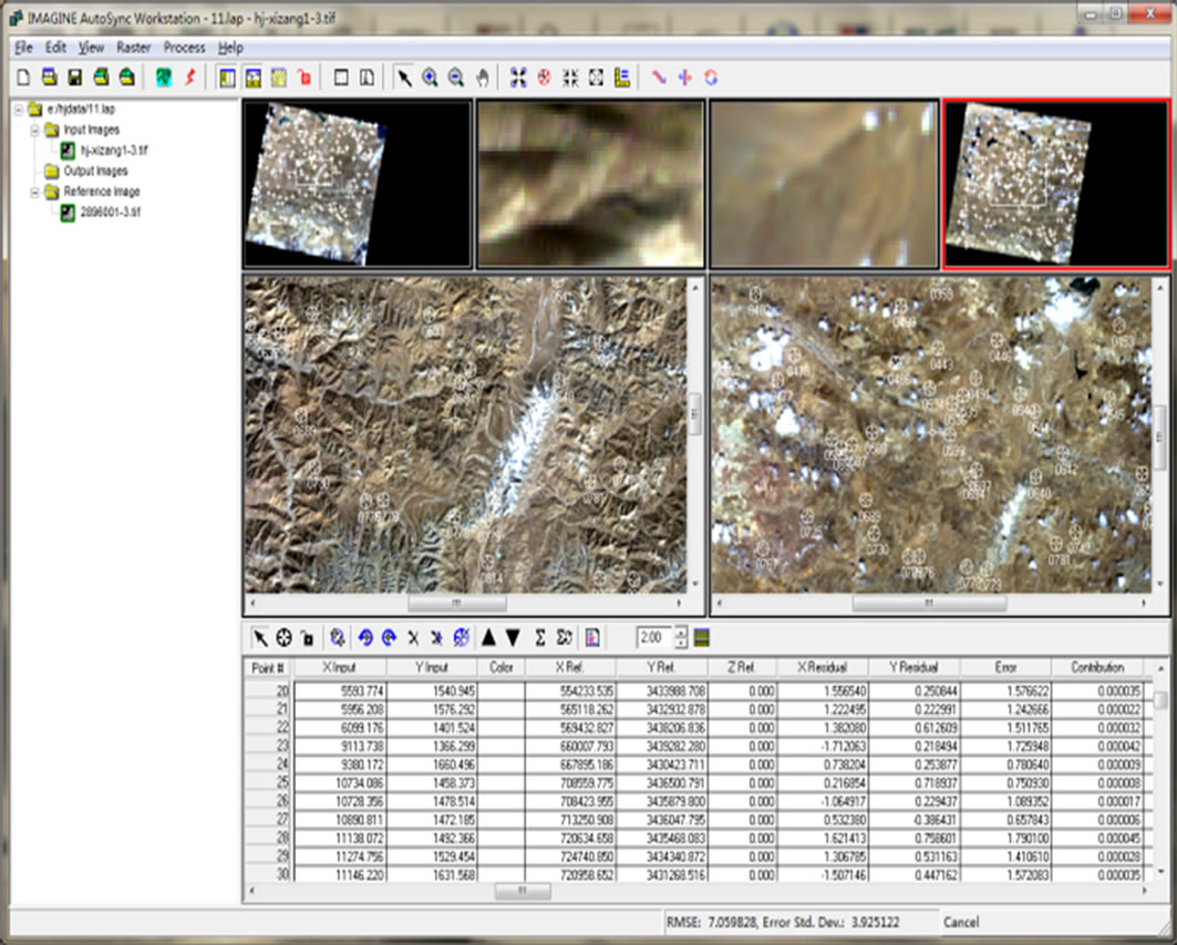
Figure 2. HJ automatically extract feature point.
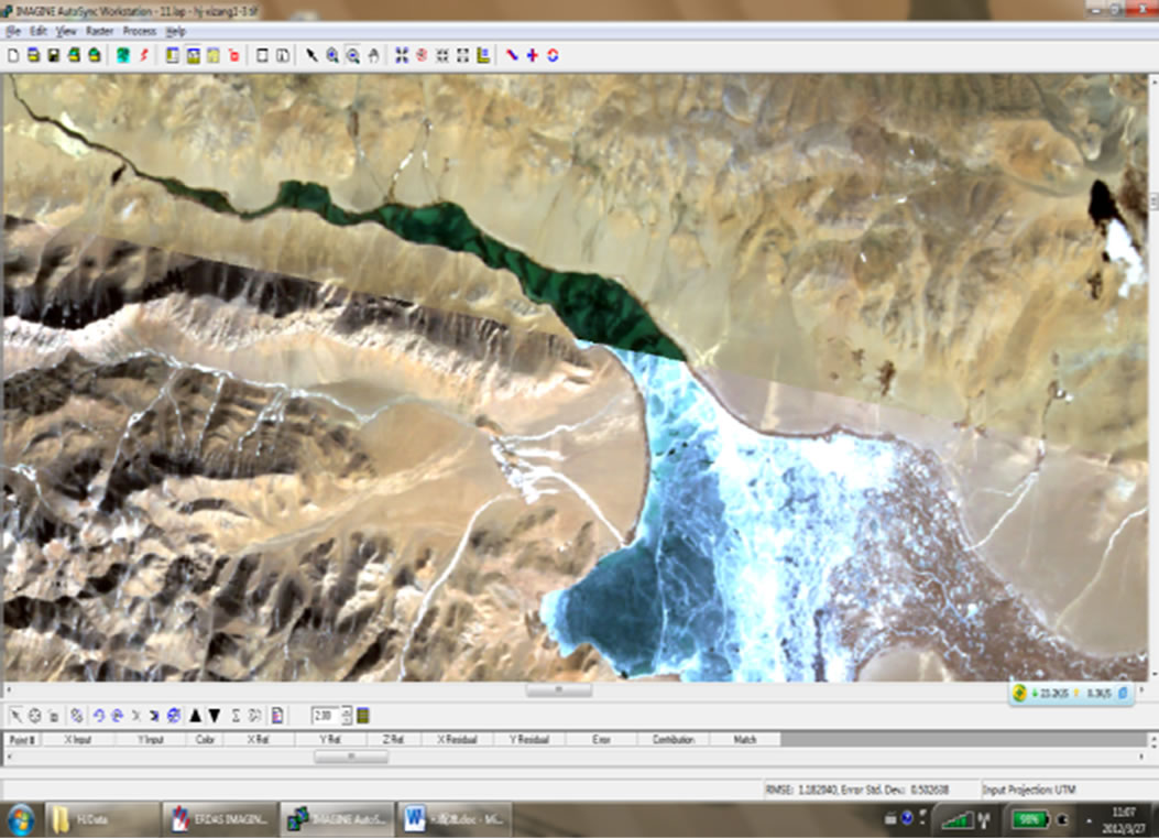
Figure 3. Local enlarged view and its distribution.
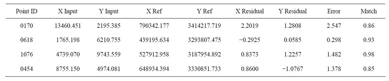
Table 1. Environment star image registration.
extraction is shown in Figure 4.
Accuracy analysis
Select some typical points from the report of ERDAS automatic registration, shown in Table 2. This table includes the minimum error and the maximum error of the registration points and maximum matched and minimum matched point.
1) Visual effect analysis. As shown in Figure 5, it is the local enlarged view of linear features joint selected after two TM images spliced.
2) The RMS error analysis. From self-generated report of ERDAS, the root mean square error is 0.183 after TM image registration.
Test 3: HJ data and TM data test
The reference image we selected is HJ data of 30 m resolution the in the test, and pre-registration image is TM image of 30 m resolution. The test data loading and feature points extracting is shown in Figure 6.
1) Visual effect analysis. As shown in Figure 7, it is the local enlarged view of linear features joint selected after TM and HJ images spliced.
2) The RMS error analysis. From self-generated report of ERDAS, the root mean square error is 4.499 after TM and HJ image registration.
Test 4: Geoeye and unmanned aerial vehicle (UAV) data
This test used two images with different sensors and different resolution to test. The test data were Geoeye data of 0.41m resolution and UAV image of 0.1 m resolution. The test data loading and feature point distribution is shown in Figure 8.
Accuracy analysis
Select some typical points from the report of ERDAS automatic registration, shown in Table 3. This table includes the minimum error and the maximum error of the registration points and maximum matched and minimum matched point.
1) Visual effect analysis, as shown in Figure 9, it is the partial enlarged view of linear features joint selected after Geoeye and uav images spliced.
2) The RMS error analysis, from self-generated report of ERDAS, the root mean square error is 14.396 after Geoeye and uav images registration.
4.2. Results of Test
From the tests above we can find that for different images, the registration accuracy of image Autosync automatic registration module is quite different. For image of the same sensor and resolution, the registration precision is higher and lower for image of different sensors and resolutions. For image of different platforms and resolutions, after registration, the accuracy is worst. The detailed comparison is shown in Table 4.
5. Conclusions
The conclusion can be obtained from the analysis, by using Image Autosync to register multi-source remote sensing Image and through analyzing the registration precision and registration efficiency of each experiment (this paper does not involve the time), that automatic registration accuracy of homologous data is the highest, registration accuracy of different source but the same resolution image take second place, and registration accuracy of different source different resolution image is the worst. The reasons for the differences of registration precision mainly include the following:
1) The quality of image affects the registration accuracy directly. The HJ image and TM image are both 30 m resolution, but their respective registration accuracy is discriminating, this mainly because imaging quality of the TM images is better.
2) The registration accuracy of the same sensor images is higher than different sensor precision, which is mainly caused by imaging time and point of view with the different sensors. Even if the same target in different sensor image can also present inconformity scales. Image Autosync realizes automatic registration only once, if realizes the thoughts of secondary registration from coarse to refined, it will improve their registration accuracy as to the registration of different source remote sensing data.
3) From the tests above, we can find different sources for remote sensing data, the bigger the gap between the resolution, the worse the registration accuracy. It mainly because the bigger the gap between the resolution, the actual distance gap of each pixel resolution representative will be bigger, so the precision of the feature points extracted can be reduced, and finally results in a lower
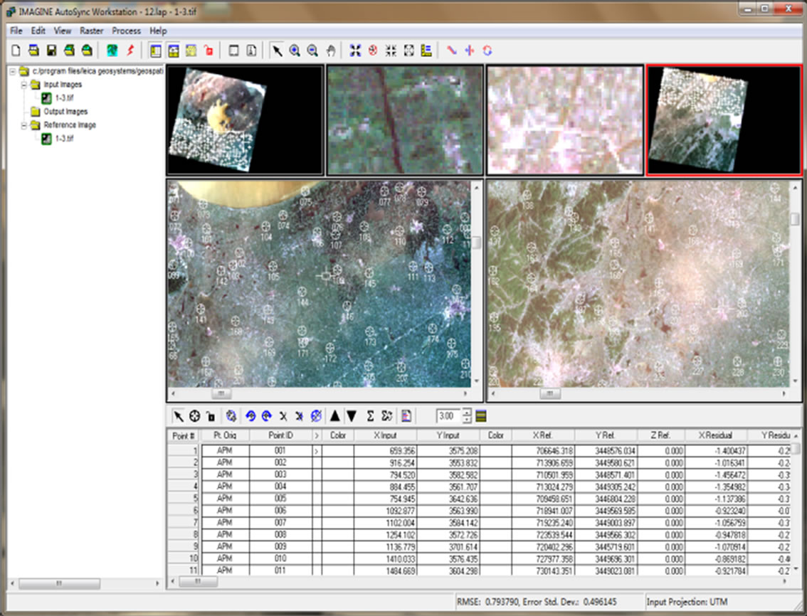
Figure 4. TM automatically extract feature points.
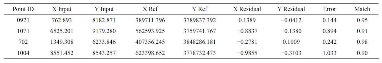
Table 2. TM image registration.
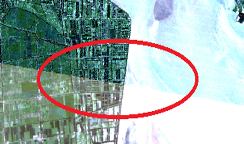
Figure 5. Local enlarged view and its distribution.
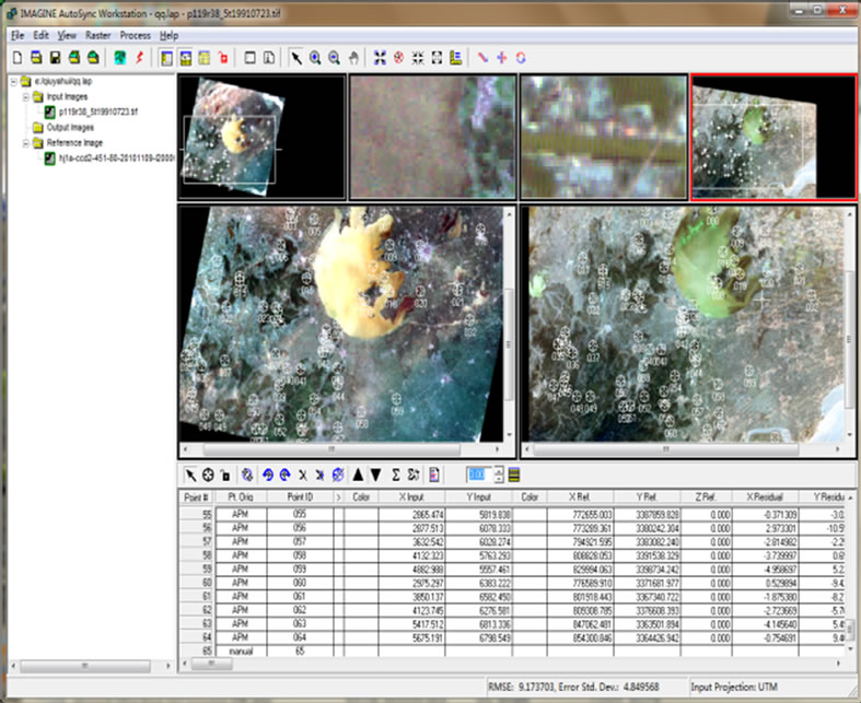
Figure 6. TM and HJ automatically extract feature.
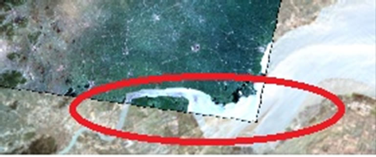
Figure 7. Local enlarged view points and its distribution.
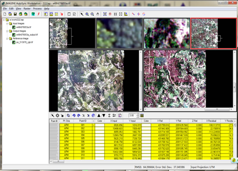
Figure 8. Geoeye and uav data automatically.
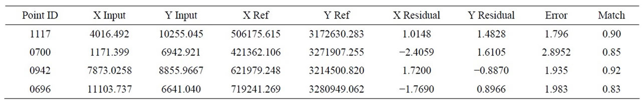
Table 3. Geoeye and uav image registration.
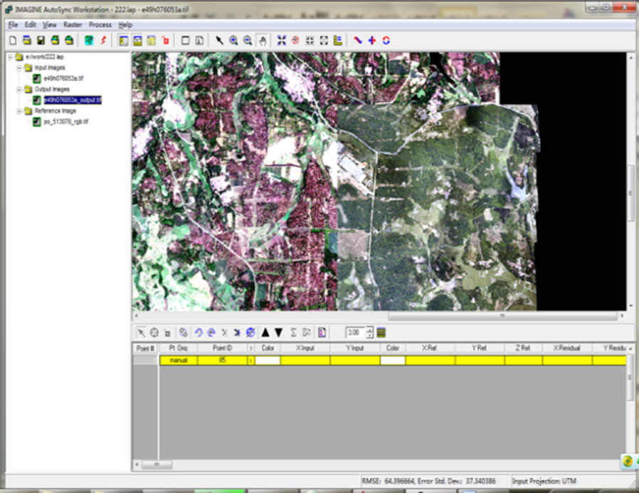
Figure 9. Partial enlarged view of extracted feature points.

Table 4. Automatic-registration-accuracy comparison of multi-source remote sensing data.
registration precision.
6. Acknowledgements
This study is financially supported by National Natural Science Foundation of China (41071328); National key basic research development planning (973) project (2007 CB209400). The ministry of education in the new century talents support plan funded projects (NECT-07- 07098); Mining spatial information technology state bureau of surveying and mapping key laboratory open fund project (KLM200816).
REFERENCES
- L. Yu, D. R. Zhang and E. J. Holden, “A Fast and Fully Automatic Registration Approach Based on Point Features for Multi-source Remote-Sensing Images,” Computers & Geosciences, Vol. 34, No. 7, 2008, pp. 838-848. doi:10.1016/j.cageo.2007.10.005
- J. W. Wu and Y. P. Qin, “The Influencing Factors Analysis of Multi-Source Remote Sensing Image Polynomial Registration Accuracy,” Computer Engineering and Applications, Vol. 45, No. 32, 2009, pp. 153-155.
- L. G. Wan and Y. L. Shi, “The Rapid Image Registration Based on AutoSync,” Surveying and Mapping, Vol. 33, No. 3, 2010, pp. 103-106.
- G. S. Li, J. X. Zhang and W. D. Song, “The Automatic Extraction of Control Points in Remote Sensing Image Registration,” Journal of Liaoning Engineering Technology University, Vol. 24, No. 1, 2005, pp. 41-44.
- A. D. Ventura, A. Rampini and R. Schettini, “Image Registration by Recognition of Corresponding Structures,” IEEE Transactions on Geo-Science and Remote Sensing, Vol. 28, No. 3, 1990, pp. 330-334.
- G. Wang, “The Rapid Method of Remote Sensing Image Registration Based on ERDAS IMAGINE 9.1,” Xinjiang Environmental Protection, Vol. 32, No. 1, 2010, pp. 27- 29.
- S. L. Zhu, B. S. Zhu, G. W. Wang, et al., “The Processing Principle and Application of Remote Sensing Image,” Science Press, Beijing, 2006.
- S. T. Liu and S. Q. Yang, “Research Progress of Image Registration Technique,” Lighting and Control, Vol. 14, No. 6, 2007, pp. 99-105.
- Z. X. Zhang, J. Q. Zhang, M. S. Liao, et al., “The High Precision Automatic Registration of Remote Sensing Image,” Wuhan: Wuhan Technical University of Surveying and Mapping, Vol. 23, No. 4, 1998, pp. 4-8.
- X. Wang and C.-H. Zhao, “The Application of Image Registration Based on ERDAS IMAGINE Software System,” Power System Engineering, Vol. 21, No. 2, 2005, pp. 59-62.