Open Journal of Fluid Dynamics
Vol.3 No.2(2013), Article ID:33656,11 pages DOI:10.4236/ojfd.2013.32015
Numerical Investigation of an Impinging Diffusion Flames-Effects of Fuel Variability
1Laboratoire de Mécanique Avancée—LMA, Bab-Ezzouar, Alger, Algeria
2Laboratoire de Mécanique des Fluides, EMP, Bordj El Bahri, Alger, Algeria
Email: ghitinadjib@yahoo.fr
Copyright © 2013 Nadjib Ghiti et al. This is an open access article distributed under the Creative Commons Attribution License, which permits unrestricted use, distribution, and reproduction in any medium, provided the original work is properly cited.
Received January 16, 2013; revised February 17, 2013; accepted February 25, 2013
Keywords: Flame; Diffusion; Turbulent; Methane; Propane; Butane
ABSTRACT
In our study, we investigate the differences between the combustion of different hydrocarbon fuels CH4, C3H8, C4H10. A numerical simulation of an impinging jet diffusion flames is used. The jet injector has a 10 mm in diameter and the distance between the jet flame and the vertical wall is 2 time half diameter. The fuel jet velocity was fixed for 11.8 m/s, corresponding to a Reynolds number of 6881. The flame characteristics varied from hydrocarbon to another for the same Reynolds number. The combustion products of CO, CO2, NO, OH, are depending on the methane and propane and butane flames for the same conditions. The temperature of the flame was varied from hydrocarbon to another the same as for the chemical species production rate. The concentration of the thermal and prompt NO pollutant depends on the temperature flow field and on the thermochemical characteristics of the hydrocarbon fuels.
1. Introduction
A diffusion flame is a very common practical system, such as a match flame or a candle flame, and is fundamental to many more complex systems. However, in a diffusion flame there is a relatively long time scale, allowing sufficient recombination reactions to take place such that it involves complex interaction of flow, transport and chemistry. There is more chemical and physical interaction in diffusion flames than in a premixed flame. The first systematic analysis of a confined, jet diffusion flame dates back to 1928 by Burke and Schumann (published in 1948) [1]. Due to environmental concerns, the amount of NOx emission in combustion processed and its formation mechanism have always been of interest. Being of particular interest is source of nitric oxide, which is a major pollutant to the atmosphere. It has been postulated that there are two major mechanisms Zeldovich thermal and Fennimore prompt NO in the production of total NO. Barlow and Carter (1993) [2] reported a rather complete simultaneous measurement on temperature and species concentrations (NO, OH, and major species) in hydrogen flames. However, the amount of naturally generated NO in a gas phase hydrocarbon flame is very small, and most measurements were done with a certain amount of NO addition.
Dong et al. [3] studied the characteristics of an impinging inverse diffusion flame jet the length of the jet impingement region, the characteristic of the wall gauge static pressure and the heat flux in the impingement region they provide a correlation between heat transfer performance and the hydrodynamic behavior, which facilitates the optimization of the jet impingement system design and operation. The aim is to understand the characterization of the extinction limits of fuel-air mixtures from low extinction strain rate methane-air flames to high extinction strain rate ethylene-air flame. Sarnacki et al. [4] reported an experimental and computational work, and they found that the variation of local extinction strain rate with changes in separation distance was within uncertainty of the experimental data. Zhen et al. [5] investigated the thermal and heat transfer behaviors of multifuel jet inverse diffusion flame with induce swirl and non-swirling under identical air/fuel rates. Flame appearances, temperature fields and wall static pressures were examined, and they found that the main reaction zone in the swirling flame is closer to the burner exit and the flame length is much shorter than the non-swirling flame and the wall static pressure and radial heat flux both are influenced by the swirl effect. A large eddy simulation technique was used to study the fuel variability on the dynamics of hydrogen and syngas impinging flames by Mira Martinez et al. [6] including a pure H2 and (20% CO, 80% H2), (40% CO, 60% H2), (20% CO, 20% CO2, 60% H2) the results of their study show that the flames develop vertical structures in the primary jet associated with the buoyancy and shear layer instability, and the wall jet progresses parallel to the impinging plate forming large scale vortex rings at different locations and strengths as a consequence of the fuel compositions.
Choe McDaid et al. [7] studied the effect of ignition location on the propagation of premixed and diffusion flames of hydrogen and mixtures of hydrogen and carbon dioxide towards. They found that the fuel velocity and Reynolds had a large effect on the observed flame velocities, and the type of the fuel affected the velocities and accelerations of the flame front. Experimental and numerical study had been conducted by Subhash et al. [8] to investigate the occurrence of off stagnation peak for laminar/air flame impinging on a flat surface of this off stagnation peak using a commercial CFD code Fluent. They found that this off stagnation in heat flux is primarily due to the peak in the axial velocity close to the impingement surface. Jaramillo et al. [9] applied the DNS and RANS techniques to study the fluid flow and heat transfer in plane impinging jets. The DNS results have been used as reference solution to assess the performance of several Reynolds averaged Navier Stokes (RANS) models. However all the models predict correctly the local Nusselt number at the stagnation region to investigate the complex flow field of an impinging jet Naseem et al. [10] used an LES simulation with a dynamic smagorinsky model. The large eddy simulation helps to understand the reason of occurrence of second peak in the radial distribution of Nusselt number at the target wall. They found that the LES simulation of a complex flow impinging jet is highly sensitive to the quality of the grid.
Zhen et al. [11] studied the emission of CO and NOx from swirling and non-swirling of an impinging inverse diffusion flames and they found that the parameters of air jet Reynolds numbers, overall equivalence ration and Nozzle to plate distance have significant influence on the overall pollutants emission. To reduce the NOx production a new down fired combustion technology based on multiple injection and multiple staging was developed by Min Kuang et al. [12]. An experimental study was performed by Zhen et al. [13] to investigate the effects of the nozzle length on the air pollutant emission and noise radiation. They found that the noise radiation from the inner reaction cone of the flame is stronger than that from the lower and upper parts of the flame for the stoichiometric air/fuel ration. Zhen et al. [14] performed an experimental work to compare between the emission and impingement heat transfer behaviors liquefied petroleum gas added of hydrogen and methane air flames
(LPG-H2-air) and (CH4-H2-air) comparison shows a more significant change in the laminar burning speed, temperature and CO/NOx emissions in the CH4 flames. Gurpreet et al. [15] investigated the heat transfer charactiristics of natural gas/air swirling flame impinging on a flat surface the dip in heat flux at and around stagnation point was observed in almost all cases which could be the main cause of non uniformity even in case of heating with swirling impinging flames.
Nadjib et al. [16] investigated the influence of the nitrogen dilution on the extinction of methane impinging diffusion flame, and they found that when the dilution rate increased the extinction of the diffusion flame increased.
In the current study, we investigated an impinging diffusion flame with three fuels, Methane, Propane and Butane with fixed fuel jet velocity. We also reported on the temperature response to the increase of the CH atom mole fraction, on the other hand we studied the relation between NO fraction production and heating high temperature for a non-premixed turbulent hydrocarbons jet flame situation.
2. Mathematical Model
2.1. Turbulent Governing Equations
In the present study, Fluent [20] (commercial CFD software) was used to model the flow field and heat transfer for diffusion turbulent methane/air flame impinging vertically on a flat surface with a reduced reaction mechanism (8 species are considered).
The general form of transport equations for two dimensional stationary turbulent reactive flows can be written as:
 (1)
(1)
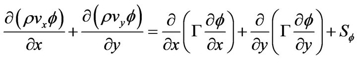 (2)
(2)
where  denotes 1,
  and diffusion coefficient
 is 0,
is 0,  and
and  respectively.
  is a source term. Fluent uses a control-volume-based technique to convert the governing equations to algebraic equations that can be solved numerically.
In order to resolve the turbulent flow problem we are used K-Epsilon turbulent RNG based model.
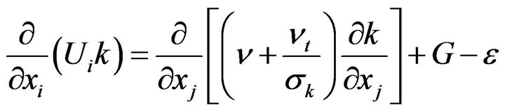 (3)
(3)
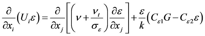 (4)
(4)
where 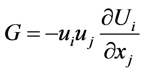 and
and 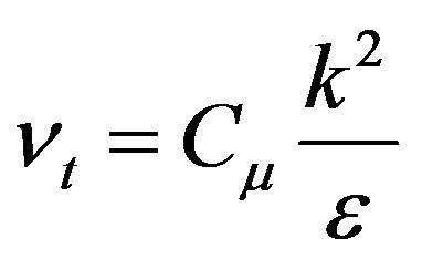
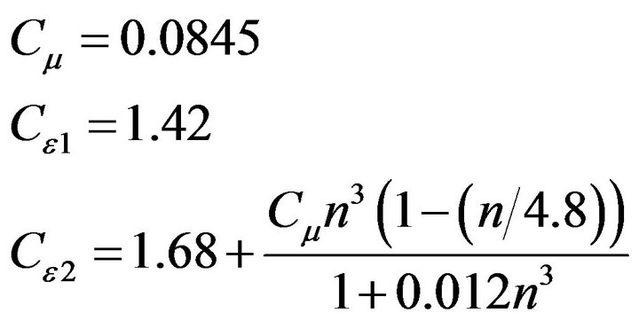
The model constants appearing in the above equations are
 and
and .
.
The effects of the mean strain rate and mean rotation on turbulent diffusion have been affected by using the renormalized RNG k- model Yakhot et al., 1992 [21], which employs equations of the same form as the standard k-
 model. The RNG k-
 model assumes different model coefficients evaluated by the renormalization group theory which vary with the ration of the turbulent to the mean strain, n, as described below:
 (5)
(5)
with
where
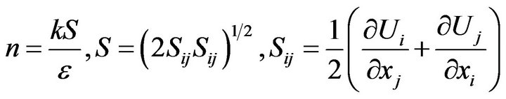 (6)
(6)
Though the modification of the above constants of the model, it is intended to simulate and control the modelling of the energy dissipation. The RNG k- model is a modification version of the standard k-
 turbulent model. It adopts a non-equilibrium strain parameter
 , Where S is the strain rate modulus and the ratio
  is the turbulence time scale.
2.2. Modeling Non-Premixed Combustion
In non-premixed combustion, fuel and oxidizer enter the reaction zone in distinct streams. This is in contrast to premixed systems, in which reactants are mixed at the molecular level before burning. Examples of non-premixed combustion include methane combustion, pulverized coal furnaces, and diesel (compression) internalcombustion engines.
In order to resolve the turbulent chemistry interaction we are focused to use Pre PDF model based on the resolution of mean transport species equation and its variance
 [20].
[20].
 (7)
(7)
 (8)
(8)
The species fractions considered in this investigation are 
In order to model nitric oxide formation in a flame, the chemical reactions involving nitrogen compounds must be taken into account. The reactions
 are the principle mechanisms in forming Zeldovich “thermal” NO; the reactions
  are the major paths in forming Fenimore “prompt” NO. In the numerical work, both Zeldovich thermal and Fenimore prompt formation of NO were included.
2.3. Computational Domaine
Using a 2D model, the impingement surface is parallel to the fuel jet; and the jet was spreading vertically on the impinging plate. The diameter of the fuel jet is 10 mm Figure 1 a total of seven transport equations (continuity, axial, and radial momentums, turbulence kinetic energy and its dissipation rate, energy, and radiative intensity), are solved using the commercial CFD package FLUENT [20]. A second-order discretization scheme was used to solve all governing equations. Solution convergence was determined by two criteria. First is ensuring that the residuals of the solved equations drop below specified thresholds set at 10−3 for all variables, while a residual of 10−6 was used for the energy equation. The second convergence criterion is ensuring that the value of a sensitive property (e.g., concentration of a radical species) at a critical spatial location has stabilized and is no longer changing with iterations.
Figure 1. Schematic of mesh domain and boundary conditions for jet diffusion flame.
3. Numerical Results
In this simulation the temperature and concentration of major species C4H10, C3H8, CH4, H2, H2O, CO2, N2, and O2 and minor species NO, CO, and OH was performed using Fluent software code. CH4, C3H8, C4H10, was used as the fuel in the impinging jet.
Velocity magnitude, flame temperature and the structure of the turbulent flame region were compared with different fuel jet flames.
Figures 2-6 show contours plots for temperature and mass fractions of OH and CO2 and OH and NO and production rate plotted versus mixture fraction for flames C4H10, C3H8, and CH4 at the same axial location.
The effect of N2 dilution level, in the fuel stream, on the flame temperature is quite substantial with a drop from 1700 K in the case propane flame, to 1400 K in case of butane flame. The temperature at the centerline is 420 K and is the same for all cases. The mean temperature in the jet vicinity of the flow is 1200 K and is also consistent between all flames Figure 2 this result is compared with the experimental data in references [16-19] for the same authors. When we look in Figure 3 we observe that the mass fraction of CO2 is maximal for the butane jet flame. The same results are obtained in Figure 4.
Figures 7 and 9 show how the calculated NO and CO2 concentrations vary with the three jet fuels for the same simulation conditions.
Figures 7-10 show radial profiles of temperature and mass fractions of OH and CO and NO and turbulent intensity for turbulent flames C4H10, C3H8, and CH4 at an axial position of 100 mm above the jet exit.
Figure 7 shows radial profiles of mean NO mole fractions for the same flames and positions as those in Figure 10 the NO distribution for flame C4H10 is different
Figure 2. Contours of temperature for different hydrocarbon fuels.
Figure 3. Contours of CO2 mass fraction for different hydrocarbon fuels.
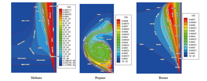
Figure 4. Contours of OH mass fraction for different hydrocarbon fuels.
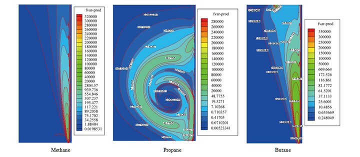
Figure 5. Contours of fraction variance production rate for different hydrocarbon fuels.
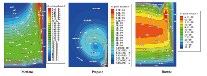
Figure 6. Contours of NO mass fraction for different hydrocarbon fuels.
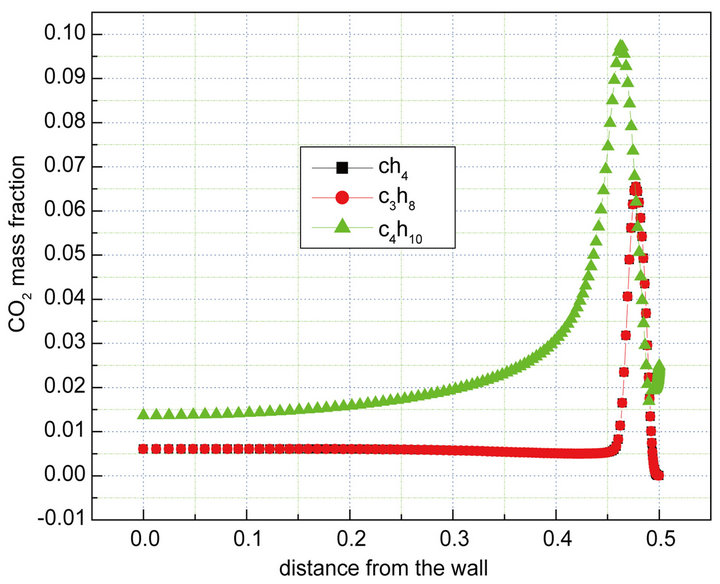
Figure 7. Dioxide mass fraction for methane, propane and butane flames.
Figure 8. Turbulent intensity profiles for methane, propane and butane flames.
Figure 9. NO concentration profiles for methane, propane and butane flames.
Figure 10. Concentrations of fuels mass fraction for methane, propane and butane flames.
from the other two flames. At the first axial position (100 mm), the NO distribution is quite wide and the mean peak NO is almost three times that of other flames.
The NO formation rate is significantly higher in the case of butane fuel compared with methane and propane fuels Figure 9 due to the higher O atom and CH concentrations promoted by the fuel oxidation.
Also shown in Figures 11-13 is the concentration of the NO production in the three flames zone on the same horizontal positions calculated from the turbulent flames modeling for the propane and butane flames more NO concentration near the impinging wall due to the effect of molecular weight on the mixing with the surrounding air.
The mean NO mole fractions for flame CH4 at the positions of 100 and 200 and 300 mm and 500 mm have the same peak of 2.5 ppm. For flames C3H8 and C4H10 the NO distribution is different from that of CH4 flame. A distinct peak close to the reaction zone location appears for both flames. At locations 100 and 200 mm, flame C3H8 has a mean NO peak level which is almost half that of the peak level for flame C4H10, while at location 200 mm, the peak level for both flames is similar. It is worth noting that the peak temperature is roughly the same for all locations and that the peak NO levels reported here for all flames are very small when compared with standard diffusion flames with similar Reynolds numbers. This indicates that dilution effects are presented in Figures 12 and 13.
4. Conclusions
In this study, we investigated the characteristics of three hydrocarbons methane, propane and butane fuel flames. The temperature and species and NO production of turbulent jet flames under non-premixed conditions are investigated.
Figure 11. Radial profiles of mean NO mass fraction at different radial locations for methane flame.

Figure 12. Radial profiles of mean NO mass fraction at different radial locations for propane flame.
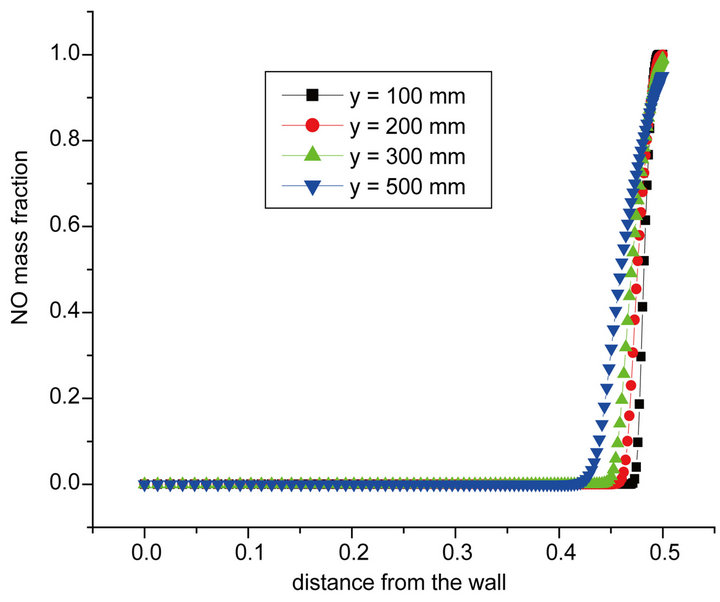
Figure 13. Radial profiles of mean NO mass fraction at different radial locations for butane flame.
- The flame temperature varied with the fuel type with the increasing of CH atom. We obtain an increase in flame temperature level. From the numerical results of simultaneous Methane Propane Butane calculations- We concluded that the turbulent flame propagation velocity varied from a fuel to another and the changing in the fuel type will influence on the NO masse fraction produced. The same conclusion is obtained for the other species CO, CO2.
REFERENCES
- S. P. Burke and T. E. W. Schumann, “Diffusion Flames,” Proceedings of the Symposium Combustion, Vol. 1-2, No. 1, 1948, pp. 2-11.
- R. S. Barlow, and C. D. Carter, “Raman/Rayleigh/LIF Measurements of Nitric Oxide Formation in Turbulent Hydrogen Jet Flames,” 1993.
- L. L. Dong, C. S. Cheung and C. W. Leung, “Characterization of Impingement Region from an Impinging Inverse Diffusion Flame Jet,” International Journal Heat and Mass Transfer, Vol. 56, No. 1-2, 2013, pp. 360-369. doi:10.1016/j.ijheatmasstransfer.2012.08.064
- B. G. Sarnacki, G. Esposito, R. H. Krauss and H. K. Chelliah, “Extinction Limits and Associated Uncertainties of Nonpremixed Counter Flow Flames of Methane Ethylene, Propylene and n-Butane in Air,” Combustion and Flame, Vol. 159, No. 3, 2012, pp. 1026-1043. doi:10.1016/j.combustflame.2011.09.007
- H. S. Zhen, C. S. Cheung, C. W. Leung and H. B. Li, “Thermal and Heat Transfer Behaviors of an Inverse Diffusion Flame with Induced Swirl,” 2012.
- D. Mira Martinez, X. Jiang, C. Moulinec and D. R. Emerson, “Numerical Investigation of the Effects of Fuel Variability on the Dynamics of Syngas Impinging Jet Flames,” 2012.
- C. McDaid, J. Zhou and Y. Zhang, “Experimental of Complex Flame Propagations Initiated at Different Locations of an Impingement Configuration,” 2012.
- S. Chander and A. Ray, “Experimental and Numerical Study on the Occurrence of Off-Stagnation Peak in Heat Flux for Laminar Methane/Air Flame Impinging on a Flat Surface,” International Journal of Heat and Mass Transfer, Vol. 54, No. 5-6, 2011, pp. 1179-1186. doi:10.1016/j.ijheatmasstransfer.2010.10.035
- J. E. Jaramillo, F. X. Trias, A. Gorobets, C. D. Pérez-Segarra and A. Olia, “DNS and RANS Modelling of a Turbulent Plane Impinging Jet,” International Journal of Heat and Mass Transfer, Vol. 55, No. 4, 2012, pp. 789-801. doi:10.1016/j.ijheatmasstransfer.2011.10.031
- N. Uddin, S. O. Neumann and B. Weigand, “LES Simulation of Impinging Jet: On the Origin of the Second Peak in the Nusselt Number Distribution,” International Journal of Heat and Mass Transfer, Vol. 57, No. 1, 2013, pp. 356-368.
- H. S. Zhen, C. W. Leung and C. S. Cheung, “Emission of Impinging Swirling and Non-Swirling Inverse Diffusion Flames,” Applied Energy, Vol. 88, No. 5, 2011, pp. 1629- 1634. doi:10.1016/j.apenergy.2010.11.036
- M. Kuang, Q. Y. Zhu, Z. Q. Li and X. Zhang, “Numerical Investigation on Combustion and NOx Emission of down Fired 350 MWe Utility Boiler with Multiple Injection and Multiple Staging: Effect of the Air Stoichiometric Ratio in the Primary Combustion Zone,” Fuel Processing Technology, Vol. 109, 2013, pp. 32-42.
- H. S. Zhen, Y. S. Choy, C. W. Leung and C. S. Cheung, “Effects of Nozzle on Flame and Emission Behaviors of Multi Fuel Jet Inverse Diffusion Flame Burner,” Applied Energy, Vol. 88, No. 9, 2011, pp. 2917-2924. doi:10.1016/j.apenergy.2011.02.040
- H. S. Zhen, C. S. Cheung, C. W. Leung and Y. S. Choy, “A Comparison of the Emission and Impingement Heat Transfer of LPG-H2 and CH4-H2 Premixed Flames,” International Journal of Hydrogen Energy, Vol. 37, No. 14, 2012, pp. 10947-10955. doi:10.1016/j.ijhydene.2012.04.055
- G. Singh, S. Chander and A. Ray, “Heat Transfer Characteristics of Naturel Gas/Air Swirling Flame Impinging on a Flat Surface,” Experimental Thermal and Fluid Science, Vol. 41, 2012, pp. 165-176. doi:10.1016/j.expthermflusci.2012.04.013
- N. Ghiti, A. A. Bentebbiche and R. Boulkourne, “Nitrogen Dilution and Extinction Effects for Methane Impinging Diffusion Flame,” IERI Procedia 1, No. 1, 2012, pp. 39- 46. doi:10.1016/j.ieri.2012.06.008
- N. Ghiti, A. A. Bentebbiche, S. Hanchi and R. Boulkroune, “A Study of the Interaction between a Jet Flame and a Lateral Wall,” Canadian Journal on Mechanical Sciences & Engineering, Vol. 3, No. 2, 2012, pp. 30-35.
- N. Ghiti, A. A. Bentebbiche and R. Boulkroune, “Experimental Investigation of the Interaction between Turbulent Impinging Flame and Radiation,” International Journal of Fluid Mechanics Research, Vol. 40, No. 1, 2013, pp. 1-8.
- N. Ghiti, A. A. Bentebbiche and R. Boulkroune, “Dilution Effect on the Extinction of Impinging Diffusion Flame with a Lateral Wall,” American Journal of Mechanical Engineering, Vol. 1, No. 2, 2013, pp. 30-33. doi:10.12691/ajme-1-2-2
- Guide Fluent, Vol. 4, 1997.
- V. Yakhot, et al., “Development of Turbulence Models for Shear Flow by Double Expansion Technique,” Physics of Fluids A, Vol. 4, No. 7, 1992, pp. 1510-1521. doi:10.1063/1.858424