Journal of Sustainable Bioenergy Systems
Vol. 2 No. 4 (2012) , Article ID: 26036 , 10 pages DOI:10.4236/jsbs.2012.24022
Mathematical Modelling of Biomass Gasification in a Circulating Fluidized Bed CFB Reactor
Department of Mechanical and Aerospace Engineering, University of Roma “La Sapienza”, Rome, Italy
Email: roberto.capata@uniroma1.it, mario.diveroli@uniroma1.it
Received June 6, 2012; revised July 15, 2012; accepted July 26, 2012
Keywords: Biomass; Gasification; Fluidized Bed Reactor; Syngas; Mathematical Model
ABSTRACT
The scope of the present paper is to investigate the suitability of a mathematical model for Circulating Fluidized Bed (CFB) coal combustion (developed by the International Energy Agency), to predict and simulate the performance of the 100 kWth CFB for air-blown biomass gasification. The development of a mathematical model allows to simulate the operative conditions during biomass gasification, control the quality of the synthesis gas and improve the gasifier design. The geometrical, mechanical, hydro dynamical and thermo chemical features were introduced in the model by properly setting the input file and, some changes have been made in the code to assure the final convergence. A sensitivity analysis has been performed to study the variation in the input parameters of the program, and it has been finally verified by comparing the results with the empirical data collected during coal and wood combustion tests. The program, in the same case, could not successfully run; probably depending on wood char density value. For these reason the influence of char density will be investigated. The model predicts the development of tar and other hydrocarbons, valuating the agreement between the measured and calculated efficiency. A further development, to consider solid biomass, with a certain volatile percentages (20% - 40%), as a fuel has been previewed and analyzed. Finally some investigations have been carried out to provide some useful indications for future developments of the code, in the biomass gasification modelling.
1. Introduction
Processes based on the thermo chemical conversion of biomass are nowadays rising importance, since they show an higher energy efficiency than the direct combustion. The biomass gasification appears as one of the most promising. It consists in the conversion, in a low O2-content atmosphere, of the original biomass feedstock into a combustible gas mixture, the synthesis gas, which can be used in several applications, like gas turbines. A complete knowledge of the biomass gasification process is necessary to satisfy the increasing demand on the quality of the produced gas. The development of a mathematical model provides an indispensable tool to control the operational parameters and improve the gasifier design.
A mathematical model for Circulating Fluidized Bed (CFB) coal combustion, developed by the International Energy Agency (IEA), is, hereby, used to predict and simulate the performance of a 100 kWth CFB gasifier. It derives from the initial considerations that the gasification process can be considered, on the chemical point of view, as “backward” step to the combustion, since it occurs in partial oxidation conditions. Moreover both processes can take place in a CFB reactor, presenting similar hydro dynamical and mechanical features. It means that the sub models used to describe such parameters, as the fluidization pattern of solid and gas flows, the particles size distribution, the thermal analysis, the chemical process of combustion and the post-process reactions, can be also useful to reproduce the complex of phenomena occurring during biomass gasification in a CFB reactor.
2. Biomass Gasification in a Circulating Fluidized Bed Reactor
Gasification is defined as “the thermo chemical process which converts solid or liquid fuels into a combustible gas mixture of low or medium heating value (4 - 10 MJ/Nm3;), by partial oxidation of the feedstock, in the presence of a gasifying agent (air, O2, CO2 and/or steam)”. The heat released by the partial oxidation is used to maintain the operating temperature and to develop the endothermic reactions in the gasifier. Stable gasification conditions are usually achieved for process temperature between 700˚C and 1100˚C and stochiometric air ratio (λ) between 0.2 and 0.4 [1]. Before introducing and describing the “core” of the gasifier we have to analyze the pyrolysis or devolatilization of biomass heating the biomass to a temperature between 400˚C and 600˚C (pyrolysis or devolatilization). Pyrolysis is defined as “the thermal decomposition of solid fuel in an oxygen-free atmosphere and it results in the production of solid char (10% - 25% wt. of the original biomass) and volatile matters, mainly composed of water, CO, CO2, H2, CH4, C2H6 and tar”. The presence of tar in the synthesis gas can produce several problems in the plant components: for this reason a particular attention has to be put into the control of tar formation and to the strategies for its removal. The final composition and efficiency of the synthesis gas is defined by the combined effects of pyrolysis, partial combustion and the complex equilibrium conditions given by competing reactions. Furthermore it is influenced by a number of parameters, such as the fuel composition, the stochiometric air ratio, the gasifying medium, the operating pressure and temperature and by the process technology.
Considering the available technologies for gasification, the CFB was considered to be suitable for medium-large scale gasification. Due to the unique hydro dynamical conditions in a fluidized bed furnace, CFB reactors present some interesting features which make more attracttive than other solid fuel fired boilers (excellent gas-solid and solid-solid mixing, homogeneous distribution of temperature, high conversion efficiency, in-situ sulphur removal and low NOx emissions) [2].
3. Description of the IEA Model
The original model has been developed by the IEA to simulate the coal combustion process in industrial size CFB boilers; it has been tested on several plants designed for heat and steam generation, having thermal power output within 13 and 300 MWth. It has been developed and designed to describe the overall process occurring in the reactor, including the gas evolution and solid flows, the determination of the particle size distribution, the coal conversion, the post-process reactions and the heat transfer process. It can be considered as an “engineering” model, resulting by a combination of mathematical models, available in literature, and empirical feedback [1].
Such approach is, sometimes, called “one and halfdimensional”: the Riser is discretized in vertical direction by simple cells, while a distinction between core and annulus cells is assumed in radial direction. In the dense bed region, the core cell, is divided in emulsion and bubbling phase cells, with different balancing equations. The cell structure of the CFB and the modelled gas and solid flows are reported in Figure 1. Each cell is assumed to be homogeneous in concentration and temperature.
It is organized in a series of following blocks, each one including the set of routines and subroutines necessary to reproduce a particular physic sub model; the different blocks are linked together by balancing soubroutines, until equilibrium is reached. All the demanded data to run the program have to be introduced in an input file; some of the required parameters have to be considered as input parameters, which should be properly adjusted in accordance with the experimental measures referred to the particular modelled case. The model is capable to predict the composition of the outlet gas mixture from the reactor [1].
4. Scale-Down of IEA Model to the Laboratory Systems
The performances of the IEA model have been tested on a laboratory-scale CFB (see Figure 2) unit designed for biomass gasification. It is, operated at atmospheric pressure, with process temperature within 700˚C and 900˚C and maximum thermal output of 100 kWth. It basically consists of a Riser (height: 5.5 m; circular cross section,O: 83 mm) connected to a gas-solid cyclone separator: the solid particles are separated and recirculated by a downcomer into the furnace, while the gas flow is cleaned by a ceramic filter before being collected.
The P&I diagram is shown in Figure 3.
The test bench generally operates under the following operational conditions:
• Only primary air supplied
• No flue gas recirculation
• No limestone addition
• No bottom bed discharge
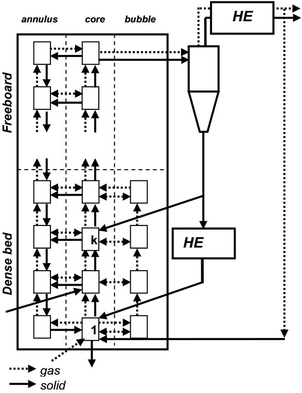
Figure 1. IEA model CFBC cell structure.
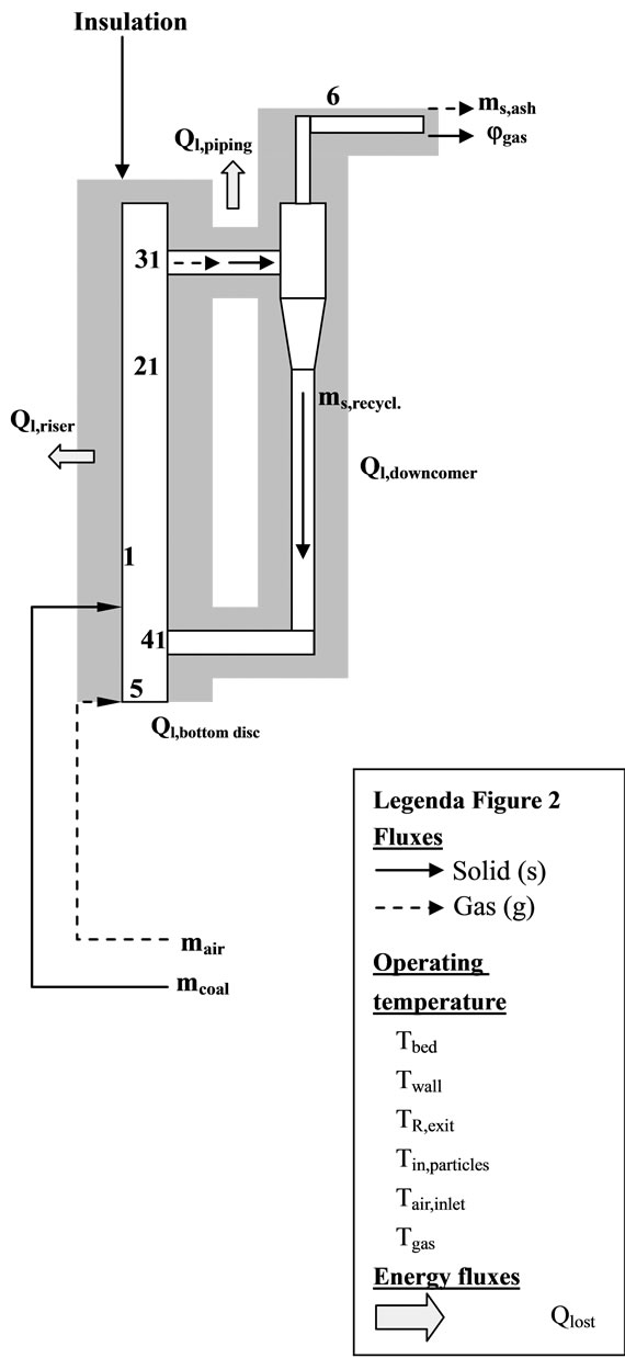
Figure 2. CFB heat exchanging model.
Unlike the boilers used for the validation of the IEA model, in this case the heat generated by oxidation of fuel has to be used into the furnace to sustain the gasification reactions; for this reason the gasifier is completely thermally insulated and it is not equipped with any other devices for heat exchange.
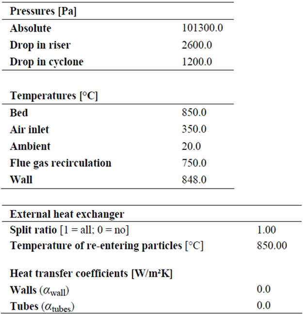
The design and operating characteristics were introduced in this work by proper input parameters.
5. Modification of the Model for the Biomass Gasification
The consistency of the approach proposed to scale down the model has been initially verified by using the IEA model to simulate coal combustion. Several experiments have been performed in the past by using the CFB test bench [2] and comparing the calculated and empirical results.
The wood characterization (composition, size particle distribution, physical properties) was introduced in the input file and two empirical cases of wood combustion were simulated, to verify the capacity of the model to simulate solid fuels other than coal.
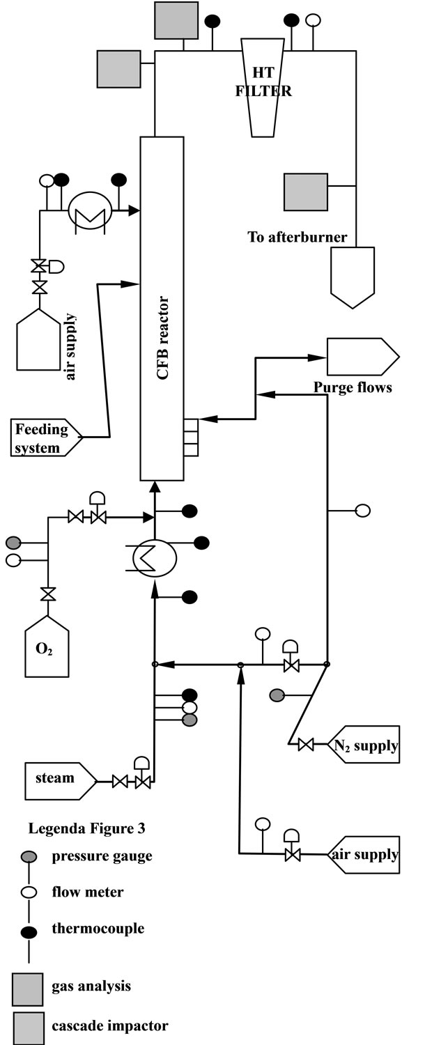
Figure 3. Gasifier P&ID model, with measure points and devices [3].
Moreover, to adapt the IEA model to simulate the wood gasification process in a small size unit, some modification have to be necessary. It has been observed that the chemical and fluidization conditions occurring during gasification can be easily reproduced by reducing λ, fule/ air ratio. However, to achieve a reliable prediction of the process, it is essential to consider the influence of the pyrolysis gas composition and the endothermic gasification reactions (not modelled or simulated by the program) on the chemical equilibrium and on the synthesis gas composition.
6. Simulation Results
6.1. Coal and Wood Combustion Simulations
The IEA model successfully runs and reaches the final convergence. The final gas composition (limited to the main components: CO, CO2 and O2) and the temperature profile along the Riser show a consistence with the available measurements. As shown in Figure 4, the calculated concentrations of CO2 and O2 deviate respecttively of 7.5% and 11.1% from the experimental ones, while a larger difference has been verified between the calculated and measured CO concentration (57.5%). These results are strongly influenced by the parameters related to the combustion kinetics, namely the char reaction constant ( ) and CO homogeneous oxidation constant (
 ), and by the attrition constant (
 ), which in the simulations could be just guessed, due to the lack of empirical data. A better approximation could be achieved by adjusting these parameters to the particular case study. These results are summerized in Table 1.
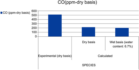
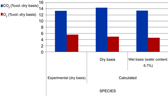
Figure 4. Comparison of experimental and calculated gas composition.
In Figure 5, the calculated temperature distribution well approaches the measured one, and a difference within 1.0% and 1.5% is noticed. The sum of the heat lost through Riser wall, and downcomer pipes, was 6.2 kWth, which is lower than the total energy losses observed during the experiments, usually between 10 - 20 kWth. However, such estimation is based on the indicative values of temperature (the wall temperature and re-entering particles temperature) assumed in this work. A more reliable validation of the heat transfer scheme could be achieved in the future by introducing the measured values of such quantities.
In case of wood combustion, the program does not, sometimes, reach the final convergence. The introduction of the wood physical properties (in particular the wood char density) in the input file leads, in the most of the cases, the program to crash and the final convergence can be reached only in correspondence of certain particular values (55 - 110 kg/m³).
It does not allow to draw general conclusions about the capacity of the IEA model to simulate solid fuel, like wood, having char density lower than coal and for this reason the obtained results are not reported in this paper.
6.2. Wood Gasification Simulations
The effects of a λ reduction on the model performance has been tested and the devolatilization model analyzed
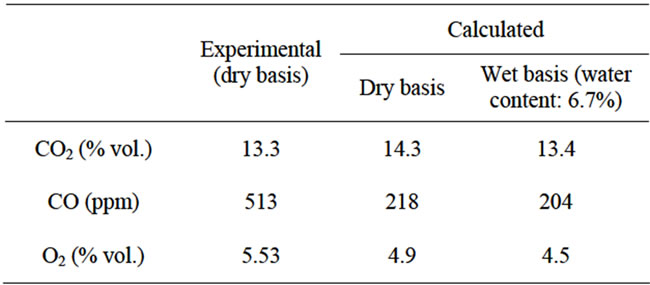
Table 1. Comparison of experimental and calculated gas concentrations.
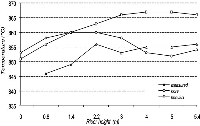
Figure 5. Comparison of measured and calculated temperature profiles.
in detail. At this stage of the work the gasification reactions have not been implemented into the code yet, thus the model can not modelling and simulate the effects of such reactions on the synthesis gas composition. The input file is modified to reproduce, as best as possible, the process conditions observed during gasification experiments by using the test bench [3] and some tests have been run. Since the gasification reactions are not modelled, the results of the simulations could not be compared with the empirical ones. However useful indications could be obtained concerning the capacity of the IEA model to simulate low values of λ, enlighten the effects that a reduction of such parameter produces on the temperature distribution along the Riser and on the final gas composition. The results are shown in Figures 6 and 7.
The reduction of λ decreases the process temperature and, due to the low O2-content atmosphere, only partial
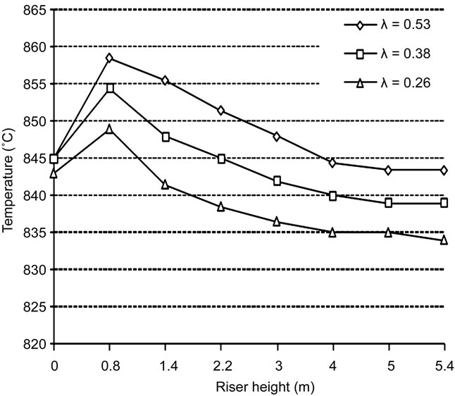
Figure 6. Effects of λ on the process temperature profile.
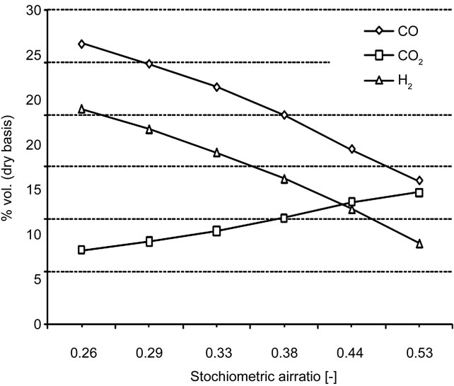
Figure 7. Effects of λ on the final gas composition.
combustion can take place into the Riser. It means that decreasing λ produces a reduction of the CO2 concentration and a simultaneous increase of CO and H2, which can not be completely oxidized into CO2 and water. The peaks observed in the temperature profiles are due to the fact that the amount of heat released by partial combustion in the lower section of the Riser is not sufficient to maintain higher level of temperature.
By the way these results represent only the expected consequences of the partial oxidation of fuel, thus they are still far to be considered as representative of the whole gasification process.
6.3. Pyrolysis Submodel
The procedure implemented in the IEA code to model the coal pyrolysis is not adequate, in case of thermal decomposition of biomass, since it does not consider the possible formation of tar and higher hydrocarbons, like methane and ethane, during the process. Dealing with coal combustion, such species can be neglected because they are assumed to be completely burned and not released in the flue gas; in case of gasification, they play a significant role in the evolution of the gas mixture and they have to be considered.
An alternative pattern is included in the IEA model, based on a mathematical model for thermal decomposition of coal proposed by D. Merrick [4], which allows to predict the production of char and volatile matters (on dry and ash free basis). The volatile matter is assumed to be formed by nine components, CH4, C2H6, CO, CO2, H2, H2O, NH3, H2S and tars. This approach results a more convenient basis for the future modelling of the gasification process. It mainly consists of a set of ten linear equations, where the mass fractions of the formed gaseous species and char are expressed as unknown variables in the vector :
:
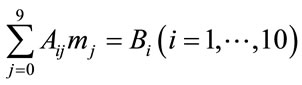 (1)
(1)
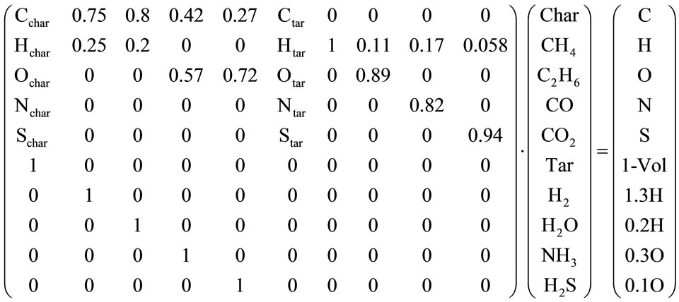
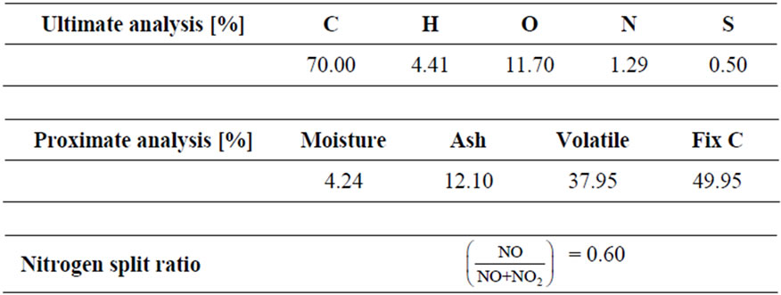
In the equations, the first six ones represent, respectively, the elemental mass balances of C, H, O, N, S and the coal mass balance. The latter four are defined by empirical correlations derived in accordance with the following statistical findings, verified by Merrick for coals having volatile content ranging between 16.3% and 37%:
● 32.7 % of H in coal evolved in CH4
● 4.4% of H in coal evolved in C2H6
● 18.5% of O in coal evolved in CO
● 11 % of O in coal evolved in CO2
In this work the Merrick model was activated, partially modified to link it to the main code and then implemented. The linear equations system, as finally defined, is reported in its matrix form:
The results can be seen in Table 2.
Due to the lack of empirical results, the reliability of such approach could be just verified by the simulation of two experimental cases of laboratory-scale fluidized bed coal pyrolysis taken from literature [5,6]. The coal used in the experiments presents a volatile content respectively equal to 47.1% and 34.6% on dry and ash free basis. In both cases the model successfully reaches convergence, and a certain amount of tar and higher hydrocarbons have been calculated as components of the volatile mixture, as shown in the Table 3 below.
The calculated molar concentrations had to be processed to present the results in suitable form to be compared with the empirical data (see Table 4). Even though the graphs in Figures 8 and 9 show a reasonable agreement
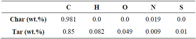
Table 2. Char and tar composition.
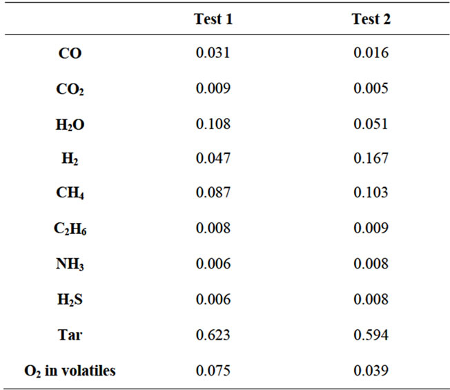
Table 3. Pyrolysis gas composition in terms of molar fraction.
between the calculated results and the experimental ones, however deviations have been reported between the calculated efficiency of pyrolysis gas (including tar) and the volatile content.. Moreover, it was noticed that only a small fraction (11% in both cases) of the O2 content of coal is used to form volatiles, which is far from the expected behaviour.
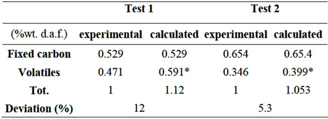
Table 4. Mass balances.
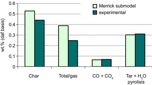
Figure 8. Validation of Merrick submodel: test 1 [5].
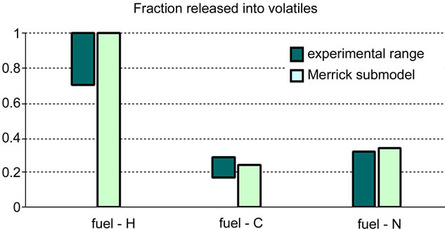
Figure 9. Validation of merrick submodel: test 2 [6].
The reason of such degree of inaccuracy is to ascribe to those equations of the linear system defined by empirical correlations, tested for the of coal pyrolysis with volatile content varying in the particular range previously mentioned, but not necessarily valid in case of fuel with higher volatile content like those used in the simulated cases [7,8].
7. Conclusions
The IEA model, initially designed to simulate the performance of industrial size installations, results to be an helpful tool in the analysis and optimization of laboratory scale units, like the tester CFB gasifier. The scalingdown approach adopted in this work can be considered to be adequate to model the particular design and operational conditions of the reactor. In case of coal combustion simulations, the program successfully achieves the final convergence.
The results confirm a good compromise between calculation values and empirical results. This condition will be optimized by choosing better input data On the other hand, the introduction of the biomass physical properties generates computational errors, and the solution of this condition represents the main problem to deal with. The results obtained at this stage of the work can only provide a rough estimation of the wood combustion process, however may be useful as starting point for future developments and studies.
The pyrolysis model based on the approach proposed by Merrick and tested in this work can be suggested as promising basis for a more accurate modelling of the biomass thermal decomposition. It is capable to predict the formation of tar and hydrocarbons as components of the volatile matter, but still requires further improvements. To improve such procedure, the empirical correlations used to build the linear equations system should be re-defined and validated in accordance with the gas composition observed during the experiments of biomass pyrolysis, in the case of solid fuels with a volatile content typically around 80%, surely higher than coal [9].
The proposed model can simulate and manage low values of λ and well approaches the expected consequences in case of incomplete combustion, but it is not suitable to reproduce the whole gasification process yet, since the gasification reactions and their reaction kinetics are not modelled in the code. Considerable efforts will be necessary to introduce in the original model a reliable model to consider the effects of these reactions on the synthesis gas composition; by the way, the analysis carried out in this work seems to encourage further investigations, with a promising future application of the IEA model, as helpful tool, in the optimization of the CFB biomass gasification process [10,11].
REFERENCES
- J. Hannes, “Mathematical Modelling of Circulating Fluidized Bed Combustion,” Kartographie und Druck Peter List, Achen, 1996.
- M. Siedlecki, “Alkali Measurements: Start-Up of the CFB Combustor and Development of Gas Sample Procedure,” M.Sc. Thesis, Delft University of Technology, Delft, 2003.
- M. Siedlecki, K. Van der Nat, E. Simeone and W. De Jong, “The First Results of Gas and Solids Characterization Obtained during Steam-Oxygen Gasification of Biomass in a 100kWth CFB Gasifier,” World Renewable Energy Congress IX, Florence, 19-25 August 2006.
- D. Merrick, “Mathematical Models of the Thermal Decomposition of Coal. 1. The Evolution of Volatile Matters,” Fuel, Vol. 62, No. 5, 1983, pp. 534-539. doi:10.1016/0016-2361(83)90222-3
- J. F. Stubington and Sumaryono, “Release of Volatiles from Large Coal Particles in a Hot Fluidized Bed Fuel,” Vol. 63, No. 7, 1984, pp. 1013-1019. doi:10.1016/0016-2361(84)90327-2
- A. N. Hayhurst and A. D. Lawrence, “The Devolatilization of Coal and a Comparison of Chars Produced in Oxidizing and Inert Atmospheres in Fluidized Beds,” Combustion and flame, Vol. 100, No. 4, 1995, pp. 591-604.
- L. Devi, K. J. Ptasinski and F. J. J. G.Jansen. “A Review of the Primary Measures for Tar Elimination in Biomass Gasification Process,” Biomass and Bioenergy, Vol. 24, No. 2, 2003, pp. 125-140.
- P. Basu, “Combustion and gasification in fluidized beds,” Taylor and Francis, Oxford, 2006. doi:10.1201/9781420005158
- C. Franco, F. Pinto, I. Gulyurtlu and I. Cabrita, “The Study of Reactions Influencing the Biomass Steam Gasification Process,” Fuel, Vol. 82, No. 7, 2003, pp. 835-842.
- X. T. Li, J. R. Grace, C. J. Lim, A. P. Watkinson, H. P. Chen and J. R. Kim, “Biomass Gasification in a Circulating Fluidized Bed,” Biomass and Bioenergy, Vol. 26, No. 2, 2004, pp. 171-193.
- K. W. Ragland, D. J. Aerts and A. J. Baker, “Properties of Wood for Combustion Analysis,” Bioresource Technology, Vol. 37, No. 4, 1991, pp. 446-452.
Nomenclature
a exponential decay constant [1/m]
CFB circulating fluidized bed
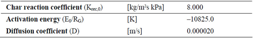
D diffusion coefficient [m²/s]
E0 activation energy [K]
Kattr attrition constant
kcycl,acc acceleration coefficient
kcycl,e cyclone entrance efficiency coefficient
kdiff diffusion coefficient in char particle [m/s]
kfrag fragmentation coefficient
k0 pre-exponential factor for CO oxidation [mol/m³s]
kreact reaction coefficient in char particle [m/s]
kreact,0 pre-exponential factor for char combustion [kg/m²sPa]
 solid mass flow [kg/s]
 gas moles [mol]
P pressure [Pa]
 heat flow [W]
R recirculation ratio [kg/kg]
Re Reynolds number
x solid species concentration
Greek
α heat transfer coefficient [W/m²K]
λ equivalence ratio
Appendix
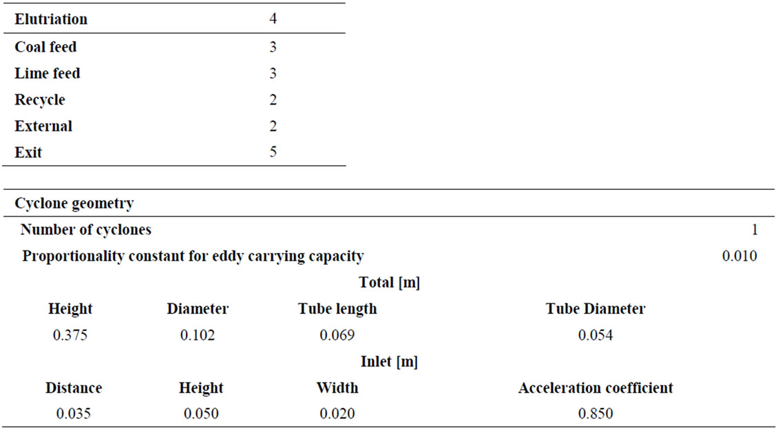
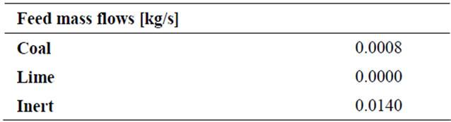
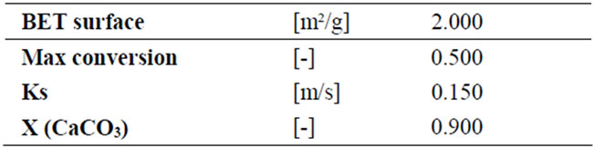
Input Parameters
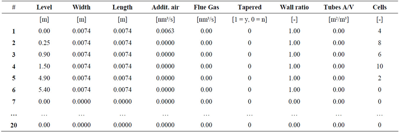
Riser geometry and state changes according to bed height
Compartment according to:
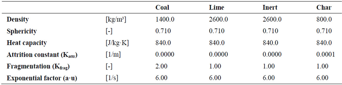
Solids properties
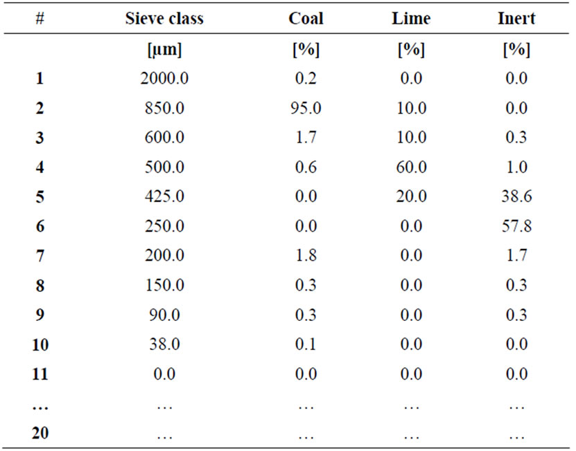
Sieve classes
Coal composition
Combustion
SO2 emissions
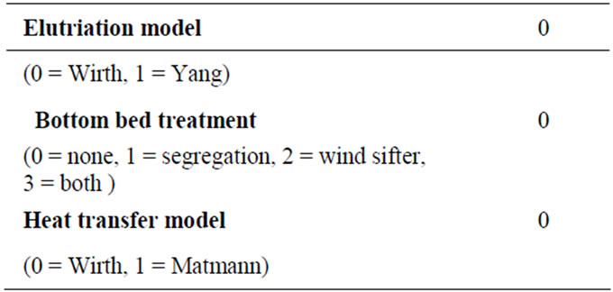
OPTIONS