Paper Menu >>
Journal Menu >>
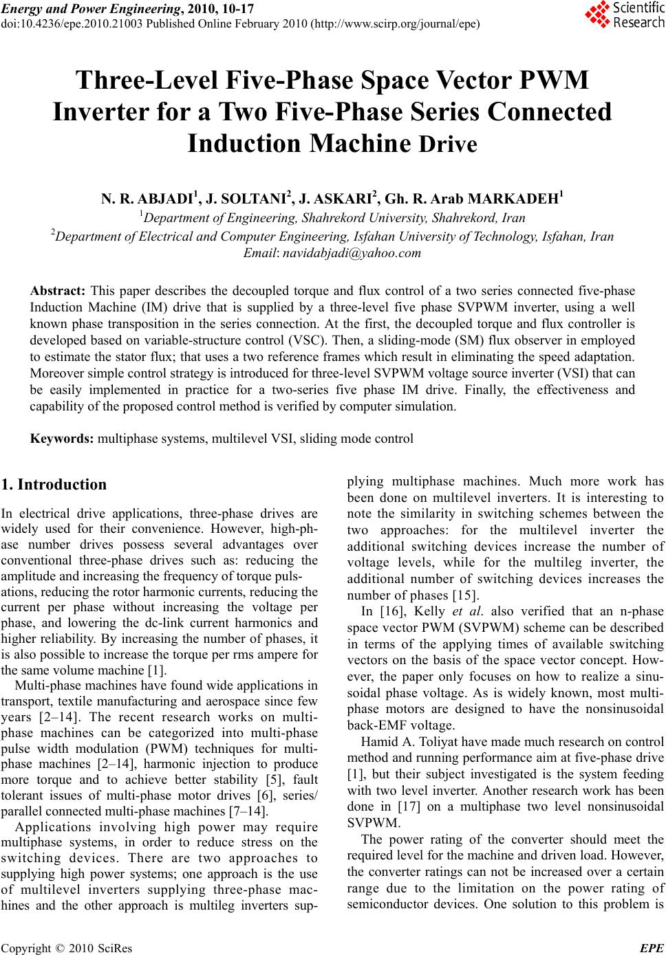 Energy and Power Engineering, 2010, 10-17 doi:10.4236/epe.2010.21003 Published Online February 2010 (http://www.scirp.org/journal/epe) Copyright © 2010 SciRes EPE Three-Level Five-Phase Space Vector PWM Inverter for a Two Five-Phase Series Connected Induction Machine Drive N. R. ABJADI1, J. SOLTANI2, J. ASKARI2, Gh. R. Arab MARKADEH1 1Department of Engineering, Shahrekord University, Shahrekord, Iran 2Department of Electrical and Computer Engineering, Isfahan University of Technology, Isfahan, Iran Email: navidabjadi@yahoo.com Abstract: This paper describes the decoupled torque and flux control of a two series connected five-phase Induction Machine (IM) drive that is supplied by a three-level five phase SVPWM inverter, using a well known phase transposition in the series connection. At the first, the decoupled torque and flux controller is developed based on variable-structure control (VSC). Then, a sliding-mode (SM) flux observer in employed to estimate the stator flux; that uses a two reference frames which result in eliminating the speed adaptation. Moreover simple control strategy is introduced for three-level SVPWM voltage source inverter (VSI) that can be easily implemented in practice for a two-series five phase IM drive. Finally, the effectiveness and capability of the proposed control method is verified by computer simulation. Keywords: multiphase systems, multilevel VSI, sliding mode control 1. Introduction In electrical drive applications, three-phase drives are widely used for their convenience. However, high-ph- ase number drives possess several advantages over conventional three-phase drives such as: reducing the amplitude and increasing the frequency of torque puls- ations, reducing the rotor harmonic currents, reducing the current per phase without increasing the voltage per phase, and lowering the dc-link current harmonics and higher reliability. By increasing the number of phases, it is also possible to increase the torque per rms ampere for the same volume machine [1]. Multi-phase machines have found wide applications in transport, textile manufacturing and aerospace since few years [2–14]. The recent research works on multi- phase machines can be categorized into multi-phase pulse width modulation (PWM) techniques for multi- phase machines [2–14], harmonic injection to produce more torque and to achieve better stability [5], fault tolerant issues of multi-phase motor drives [6], series/ parallel connected multi-phase machines [7–14]. Applications involving high power may require multiphase systems, in order to reduce stress on the switching devices. There are two approaches to supplying high power systems; one approach is the use of multilevel inverters supplying three-phase mac- hines and the other approach is multileg inverters sup- plying multiphase machines. Much more work has been done on multilevel inverters. It is interesting to note the similarity in switching schemes between the two approaches: for the multilevel inverter the additional switching devices increase the number of voltage levels, while for the multileg inverter, the additional number of switching devices increases the number of phases [15]. In [16], Kelly et al. also verified that an n-phase space vector PWM (SVPWM) scheme can be described in terms of the applying times of available switching vectors on the basis of the space vector concept. How- ever, the paper only focuses on how to realize a sinu- soidal phase voltage. As is widely known, most multi- phase motors are designed to have the nonsinusoidal back-EMF voltage. Hamid A. Toliyat have made much research on control method and running performance aim at five-phase drive [1], but their subject investigated is the system feeding with two level inverter. Another research work has been done in [17] on a multiphase two level nonsinusoidal SVPWM. The power rating of the converter should meet the required level for the machine and driven load. However, the converter ratings can not be increased over a certain range due to the limitation on the power rating of semiconductor devices. One solution to this problem is 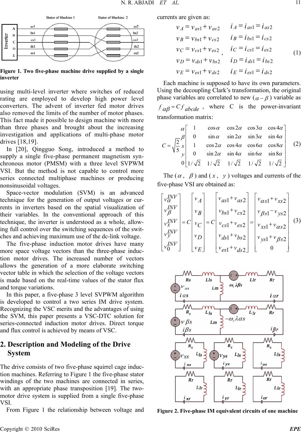 N. R. ABJADI ET AL. Copyright © 2010 SciRes EPE 11 Figure 1. Two five-phase machine drive supplied by a single inverter using multi-level inverter where switches of reduced rating are employed to develop high power level converters. The advent of inverter fed motor drives also removed the limits of the number of motor phases. This fact made it possible to design machine with more than three phases and brought about the increasing investigation and applications of multi-phase motor drives [18,19]. In [20], Qingguo Song, introduced a method to supply a single five-phase permanent magnetism syn- chronous motor (PMSM) with a three level SVPWM VSI. But the method is not capable to control more series connected multiphase machines or producing nonsinusoidal voltages. Space-vector modulation (SVM) is an advanced technique for the generation of output voltages or cur- rents in inverters based on the spatial visualization of their variables. In the conventional approach of this technique, the inverter is understood as a whole, allow- ing full control over the switching sequences of the swit- ches and achieving maximum use of the dc-link voltage. The five-phase induction motor drives have many more space voltage vectors than the three-phase induc- tion motor drives. The increased number of vectors allows the generation of a more elaborate switching vector table in which the selection of the voltage vectors is made based on the real-time values of the stator flux and torque variations. In this paper, a five-phase 3 level SVPWM algorithm is developed to control a two series IM drive system. Recognizing the VSC merits and the advantages of using the SVM, this paper presents a VSC-DTC solution for series-connected induction motor drives. Direct torque and flux control is achieved by means of VSC. 2. Description and Modeling of the Drive System The drive consists of two five-phase squirrel cage induc- tion machines. Referring to Figure 1 the five-phase stator windings of the two machines are connected in series, with an appropriate phase transposition [19]. The two- motor drive system is supplied from a single five-phase VSI. From Figure 1 the relationship between voltage and currents are given as: 12 12 12 12 12 A as as Bbs cs Ccses D ds bs E es ds vv v vv v vv v vv v vv v , 12 12 12 12 12 Aas as B bs cs Ccs es D ds bs E es ds ii i ii i ii i ii i ii i (1) Each machine is supposed to have its own parameters. Using the decoupling Clark’s transformation, the original phase variables are correlated to new ( ) variable as C ff abcde , where C is the power-invariant transformation matrix: 1coscos 2cos 3cos4 0sinsin2sin 3sin4 21cos2cos 4cos 6cos8 50sin2sin4sin6sin 8 01/ 21/ 21/ 21/ 21/2 Cx y (2) The ( , ) and ( x , y) voltages and currents of the five-phase VSI are obtained as: 12 12 2 112 12 12 12 12 0 012 INV vv vvv vas as A s xs INV vvv vvv cs bs B s ys INV CC vv v vxvv cs es C x ss INV vyvv vvv Dds bsys s INV vvvv Ees ds (3) Figure 2. Five-phase IM equivalent circuits of one machine 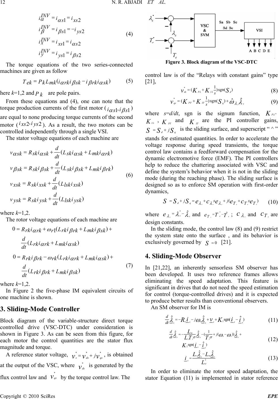 N. R. ABJADI ET AL. Copyright © 2010 SciRes EPE 12 12 12 12 12 INV iii s xs INV ii i s ys INV iii x x ss INV iii yys s (4) The torque equations of the two series-connected machines are given as follow () ii ii TPL ekk mkrkskrk sk (5) here k=1,2 andPk are pole pairs. From these equations and (4), one can note that the torque production currents of the first motor (, 11 ii s s ) are equal to none producing torque currents of the second motor (, 22 ii x sys ). As a result, the two motors can be controlled independently through a single VSI. The stator voltage equations of each machine are () () () () d vii i RLL sksk mk s ksk skrk dt d vii i RLL sksk mk s kskskrk dt d vi i RL sk lsk xsk xskxsk dt d vi i RL sk lsk ysk yskysk dt (6) where k=1,2. The rotor voltage equations of each machine are 0( ) 1 () iii RLL rkrk mk rk rrksk dii LL rk mk rk sk dt 0( ) () iii RLL rkrk mk rk rkrksk dii LL rk mk rk sk dt (7) where k=1,2. In Figure 2 the five-phase IM equivalent circuits of one machine is shown. 3. Sliding-Mode Controller Block diagram of the variable-structure direct torque controlled drive (VSC-DTC) under consideration is shown in Figure 3. As can be seen from this figure, for each motor the control quantities are the stator flux magnitude and torque. A reference stator voltage, ** * s ds qs j vv v , is obtained at the output of the VSC, where * ds v is generated by the flux control law and * qs v by the torque control law. The Figure 3. Block diagram of the VSC-DTC control law is of the “Relays with constant gains” type [21], *1 ()sgn( ) PI ds d s vS KK (8) *1 ()sgn( )ˆ ˆs PT IT qs q s s vS KK (9) where s=d/dt, sgn is the signum function, , P K I K ,PT K and I T K are the PI controller gains, dq j SS S is the sliding surface, and superscript “ ^ ” stands for estimated quantities. In order to accelerate the voltage response during speed transients, the torque control law contains a feedforward compensation for the dynamic electromotive force (EMF). The PI controllers help to reduce the chattering associated with VSC and define the system’s behavior when it is not in the sliding mode (during the reaching phase). The sliding surface is designed so as to enforce SM operation with first-order dynamics, () eee sss dq jsjs TTT SSSe ceece (10) where *ˆ ss s e and *ˆ eee T eTT ; s c and e T care design constants. In the sliding mode, the control law (8) and (9) restrict the system state onto the surface , and its behavior is exclusively governed by 0 S [21]. 4. Sliding-Mode Observer In [21,22], an inherently sensorless SM observer has been developed. It uses two reference frames allows eliminating the speed adaptation. This feature is significant in drives that do not need the speed estimation for control (torque-controlled drives) and it is expected to produce better results than conventional observers. An SM observer for IM is 1sgn( ) ˆˆ ˆ se sss s ss dj dt ivi i RK (11) 2 1 (( )) sgn( ) ˆˆ ˆ ˆ m er rs r sr r ss dj dt L LTT ii K (12) 2 ˆˆ rm s r s L L i L (13) In order to eliminate the rotor speed adaptation, the stator Equation (11) is implemented in stator reference  N. R. ABJADI ET AL. Copyright © 2010 SciRes EPE 13 Figure 4. Scheme of a five-phase three-level inverter Figure 5. The switching vectors on α-β and x-y planes frame, and the rotor Equation (12) is implemented in rotor flux frame (superscript “ r ”), which rotates with rotor flux speed, r 1sgn( ) ˆˆ sss s s s d dt iv ii RK (14) 2 1 (( )) sgn( ) ˆˆ ˆ ˆ r rr r m r rs r sr r r r ss dj dt L LT T ii K (15) Taking into consideration that the rotor flux is aligned with the reference frame, the rotor model (15) turns out to be simple: 2 1 (sgn( )) ˆˆˆ ˆ rrr m drds dr sr r r r ss d dt e L LT T ii K (16) 0 ˆr qr (17) It can be shown that the observer is stable if its gains are large enough [21]. 5. Three Level Space Vector Pwm In [20], a technique of vector space control of three-level voltage source inverter fed five-phase machines was presented. Using the same idea described in [20], in this paper a SVPWM voltage source is developed which is capable of supplying the two motor drive system with different rotor speeds. The SVPWM scheme is designed to generate an arbitrary reference voltage space vector which consti- tutes the motors main frequencies 1 and 2 . Figure 4 shows the scheme of a five-phase three-level inverter. There are 243(35) voltage vectors; the mag- nitude and distributing of voltage vectors are far more complex than five-phase two-level inverter. However, not all of vectors are suitable to vector synthesizing. Consider voltage vectors with magnitude VL 0.6472VDC , 0.6156 VV M DC , 0.3236 VV SDC and zero voltage vectors as efficient working vectors. There are 43 efficient vectors in each plane, including 30 non-zero vectors, 10 redundant and 3 zero vectors, as shown in Figure 5. The decimal numbers in Figure 5 denote the switching modes. When each decimal number is converted to a five digit number in base 3, the 2's in this number indicate that the two upper switches in the corresponding switching arms are “on” and the 1's in this number indicate that the two middle switches are “on”, while the 0's indicate the “on” state of the lower switches. The MSB (most significant bit) of the number represents the switching state of phase a, the second MSB for phase b, and so on. As shown in Figure 5, selected working voltage vectors equally divide the decagon into ten sec- tions 1, 2, ..., 10. From the average vector concept during one sampling  N. R. ABJADI ET AL. Copyright © 2010 SciRes EPE 14 * n V a V b V Figure 6. Reference vector and switching vectors in section 1 of α-β plane Figure 7. Flowchart to realize reference voltage vectors period, the reference voltage vectors on the α-β and x-y planes can be realized by adjusting the applying times of 3 vectors. Figure 6 shows each section can be divided into four smaller triangle regions, and the reference voltage vector is formed by three apical voltage vectors in this triangle [20]. For example if the reference vector is between vectors 218 and 216 in α-β plane (sector 1), and moreover it is located in region C, as shown in Figure 6, the active switching vectors are 217, 216, 108 (or 229). To control 2 series-connected motor, in half of each switching period, the α-β reference vector, in α-β plane, is used as the reference vector and in half other, the x-y reference vector, in x-y plane, is used to determine the switching vectors. This strategy can be repeated in all of the sectors and shown in flowchart of Figure 7. It is worthwhile to note using the switching vectors for example in α-β plane, by above suggested method, the x-y components are negligible and vice versa. In this way, both α-β reference vector and x-y reference vector are realized. It is better to normalize vectors by 0.3236 VV SDC , then each switching vector coordinate becomes integer as shown in Figure 6. From Figure 6, the coordinates of reference vector are obtained as follow * (c) sin 36 o an tg ctg VV (18) * sin sin 36 o bn VV (19) where is the angle between reference vector and a-axis in each section. The space vector PWM strategy is accomplished by the following equations E FGs Ea Fa Gaa E FGs Eb Fb Gbb EFGs VVV V TTTT VVV V TTTT TTTT (20) where E T, F T and G Tare the apical switching vectors in each triangle region; and s T is half of the switching period. For simplicity the switching times for all of the regions are calculated in Table 1. 6. Simulation Results The proposed control scheme is implemented in a block diagram shown in Figure 8. In this figure, only control of IM1 is illustrated (some subscripts are omitted for the sake of brevity), the same can be applied to IM2. Notice that the SM controller and observer gains are obtained by trial and errors. Similarly the coefficients of sp eed PI controller are obtained as 10 p k,1.1 i k. Simulation results are obtained for a two different five- phase squirrel cage IM with parameters shown in Table 2. The IMs speeds and stator fluxes control results are obtained and shown in Figure 9(a) and Figure 9(b) respectively. These results obtained for an exponential reference rotor speed from zero to 80 rad/s for machine 1 and an exponential reference rotor speed from zero to 40 rad/s for machine 2. The amplitudes of stator fluxes are Table 1. Calculation of switching times in each region Region A: V (,)(0,0) (,)(1,0) (,)(0,1) FsEa Eba GsFa Fbb E sFGGa Gb VV V TT VV V TT VV TTTT Region B: (,)(0,1)(1 ) (,)(1,0) (1 ) (,)(1,1) EsEa Eba FsFa Fbb GsEF Ga Gb VV V TT VV V TT VV TTTT Region C: (,)(0,1) (2 ) (,)(1,1) (, )(0,2) E sEa Ebab Fs Fa Fba GsEF Ga Gb VVV V TT VV V TT VV TTTT Region D: (,)(1,0) (2 ) (,)(2,0) (,)(1,1) E s Ea Ebab Gs Fa Fbb FsEGGa Gb VV VV TT VV V TT VV TTTT  N. R. ABJADI ET AL. Copyright © 2010 SciRes EPE 15 Table 2. Im parameters Machine 1 [23]: Pn1 3hp f 50Hz 1 P 3 1 s R 0.78 1r R 0.66 1 s L 33.15mH 1r L 33.15mH 1m L 29.7mH Machine 2 [19]: Pn2 7.5hp f 50Hz 2 P 2 2 s R 10 2r R 6.3 2 s L 460mH 1r L 460mH 2m L 420mH Figure 8. Drive system block diagram 00.5 11.5 22.5 33.5 -10 0 -50 0 50 100 wr1, wr1* < rad/ s> 00.5 11.5 22.5 33.5 -50 0 50 Time <s> wr 2, wr2* < r a d /s> (a) 00.5 11.5 22.5 33.5 4 0 0.1 0.2 0.3 0.4 0.5 Stator Flux1 <Weber> 00.5 11.5 22.5 33.5 4 0 0.1 0.2 0.3 0.4 0.5 Time <s> Stat or Flux2 <W eber > (b) 00.511.522.5 33.5 4 0 0.1 0.2 0.3 0.4 0.5 Estimat ed St at or Flux1 <Weber > 00.511.522.5 33.5 4 0 0.1 0.2 0.3 0.4 0.5 Time <s> Estimat ed Stator Flux2 <Weber > (c) 00.5 11.5 22.5 33.5 4 -10 0 10 20 Te1 <N. m > 00.5 11.5 22.5 33.5 4 -10 -5 0 5 10 15 Time <s> Te2 <N.m> (d) 00.5 11.5 22.533.54 -15 -10 -5 0 5 10 15 Time <s> ias 1 <A> (e) Figure 9. a) Rotor speeds; b) Stator fluxes; c) Estimated stator fluxes; d) Motors torques; e) Motors phase ‘a’ currents kept constant (0.4 Wb for both IMs). 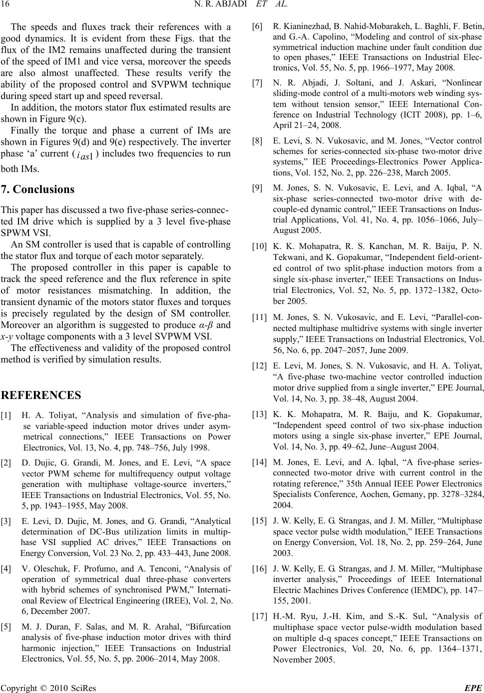 N. R. ABJADI ET AL. Copyright © 2010 SciRes EPE 16 The speeds and fluxes track their references with a good dynamics. It is evident from these Figs. that the flux of the IM2 remains unaffected during the transient of the speed of IM1 and vice versa, moreover the speeds are also almost unaffected. These results verify the ability of the proposed control and SVPWM technique during speed start up and speed reversal. In addition, the motors stator flux estimated results are shown in Figure 9(c). Finally the torque and phase a current of IMs are shown in Figures 9(d) and 9(e) respectively. The inverter phase ‘a’ current (1 ias ) includes two frequencies to run both IMs. 7. Conclusions This paper has discussed a two five-phase series-connec- ted IM drive which is supplied by a 3 level five-phase SPWM VSI. An SM controller is used that is capable of controlling the stator flux and torque of each motor separately. The proposed controller in this paper is capable to track the speed reference and the flux reference in spite of motor resistances mismatching. In addition, the transient dynamic of the motors stator fluxes and torques is precisely regulated by the design of SM controller. Moreover an algorithm is suggested to produce α-β and x-y voltage components with a 3 level SVPWM VSI. The effectiveness and validity of the proposed control method is verified by simulation results. REFERENCES [1] H. A. Toliyat, “Analysis and simulation of five-pha- se variable-speed induction motor drives under asym- metrical connections,” IEEE Transactions on Power Electronics, Vol. 13, No. 4, pp. 748–756, July 1998. [2] D. Dujic, G. Grandi, M. Jones, and E. Levi, “A space vector PWM scheme for multifrequency output voltage generation with multiphase voltage-source inverters,” IEEE Transactions on Industrial Electronics, Vol. 55, No. 5, pp. 1943–1955, May 2008. [3] E. Levi, D. Dujic, M. Jones, and G. Grandi, “Analytical determination of DC-Bus utilization limits in multip- hase VSI supplied AC drives,” IEEE Transactions on Energy Conversion, Vol. 23 No. 2, pp. 433–443, June 2008. [4] V. Oleschuk, F. Profumo, and A. Tenconi, “Analysis of operation of symmetrical dual three-phase converters with hybrid schemes of synchronised PWM,” Internati- onal Review of Electrical Engineering (IREE), Vol. 2, No. 6, December 2007. [5] M. J. Duran, F. Salas, and M. R. Arahal, “Bifurcation analysis of five-phase induction motor drives with third harmonic injection,” IEEE Transactions on Industrial Electronics, Vol. 55, No. 5, pp. 2006–2014, May 2008. [6] R. Kianinezhad, B. Nahid-Mobarakeh, L. Baghli, F. Betin, and G.-A. Capolino, “Modeling and control of six-phase symmetrical induction machine under fault condition due to open phases,” IEEE Transactions on Industrial Elec- tronics, Vol. 55, No. 5, pp. 1966–1977, May 2008. [7] N. R. Abjadi, J. Soltani, and J. Askari, “Nonlinear sliding-mode control of a multi-motors web winding sys- tem without tension sensor,” IEEE International Con- ference on Industrial Technology (ICIT 2008), pp. 1–6, April 21–24, 2008. [8] E. Levi, S. N. Vukosavic, and M. Jones, “Vector control schemes for series-connected six-phase two-motor drive systems,” IEE Proceedings-Electronics Power Applica- tions, Vol. 152, No. 2, pp. 226–238, March 2005. [9] M. Jones, S. N. Vukosavic, E. Levi, and A. Iqbal, “A six-phase series-connected two-motor drive with de- couple-ed dynamic control,” IEEE Transactions on Indus- trial Applications, Vol. 41, No. 4, pp. 1056–1066, July– August 2005. [10] K. K. Mohapatra, R. S. Kanchan, M. R. Baiju, P. N. Tekwani, and K. Gopakumar, “Independent field-orient- ed control of two split-phase induction motors from a single six-phase inverter,” IEEE Transactions on Indus- trial Electronics, Vol. 52, No. 5, pp. 1372–1382, Octo- ber 2005. [11] M. Jones, S. N. Vukosavic, and E. Levi, “Parallel-con- nected multiphase multidrive systems with single inverter supply,” IEEE Transactions on Industrial Electronics, Vol. 56, No. 6, pp. 2047–2057, June 2009. [12] E. Levi, M. Jones, S. N. Vukosavic, and H. A. Toliyat, “A five-phase two-machine vector controlled induction motor drive supplied from a single inverter,” EPE Journal, Vol. 14, No. 3, pp. 38–48, August 2004. [13] K. K. Mohapatra, M. R. Baiju, and K. Gopakumar, “Independent speed control of two six-phase induction motors using a single six-phase inverter,” EPE Journal, Vol. 14, No. 3, pp. 49–62, June–August 2004. [14] M. Jones, E. Levi, and A. lqbal, “A five-phase series- connected two-motor drive with current control in the rotating reference,” 35th Annual IEEE Power Electronics Specialists Conference, Aochen, Gemany, pp. 3278–3284, 2004. [15] J. W. Kelly, E. G. Strangas, and J. M. Miller, “Multiphase space vector pulse width modulation,” IEEE Transactions on Energy Conversion, Vol. 18, No. 2, pp. 259–264, June 2003. [16] J. W. Kelly, E. G. Strangas, and J. M. Miller, “Multiphase inverter analysis,” Proceedings of IEEE International Electric Machines Drives Conference (IEMDC), pp. 147– 155, 2001. [17] H.-M. Ryu, J.-H. Kim, and S.-K. Sul, “Analysis of multiphase space vector pulse-width modulation based on multiple d-q spaces concept,” IEEE Transactions on Power Electronics, Vol. 20, No. 6, pp. 1364–1371, November 2005.  N. R. ABJADI ET AL. Copyright © 2010 SciRes EPE 17 [18] L. Parsa, “On advantages of multi-phase machines,” 32nd Annual Conference of IEEE Industrial Electronics Socie- ty (IECON), pp. 1574–1579, 2005. [19] E. Levi, A. Iqbal, S. N. Vukosavic, and H. A. Toliyat, “Modeling and control of a five-phase series-connected two-motor drive,” The 29th Annual Conference of the IEEE Industrial Electronics Society (IECON), Vol. 1, pp. 208–2132, 003. [20] Q. Song, X. Zhang, F. Yu, and C. Zhang, “Research on space vector PWM of five-phase three-level inverter,” Proceedings of the Eighth International Conference on Electrical Machines and Systems, ICEMS, Vol. 2, pp. 1418–1421, 2005.. [21] C. Lascu, I. Boldea, and Frede Blaabjerg, “Direct torque control of sensorless induction motor drives: A sliding- mode approach,” IEEE Transactions on Industrial App- lications, Vol. 40, No. 2, pp. 582–590, March–April 2004. [22] C. Lascu and G.-D. Andreescu, “Sliding-mode observer and improved integrator with DC-Offset compensation for flux estimation in sensorless-controlled induction motors,” IEEE Transactions on Industrial Electronics, Vol. 53, No. 3, pp. 785–794, June 2006. [23] K. N. Pavithran, R. Parimelalagan, and M. R. Krishna- murthy,” Studies on inverter-fed five-phase induction motor drive,” IEEE Transactions on Power Electronics, Vol. 3, No. 2, pp. 224–235, April 1988. |