Paper Menu >>
Journal Menu >>
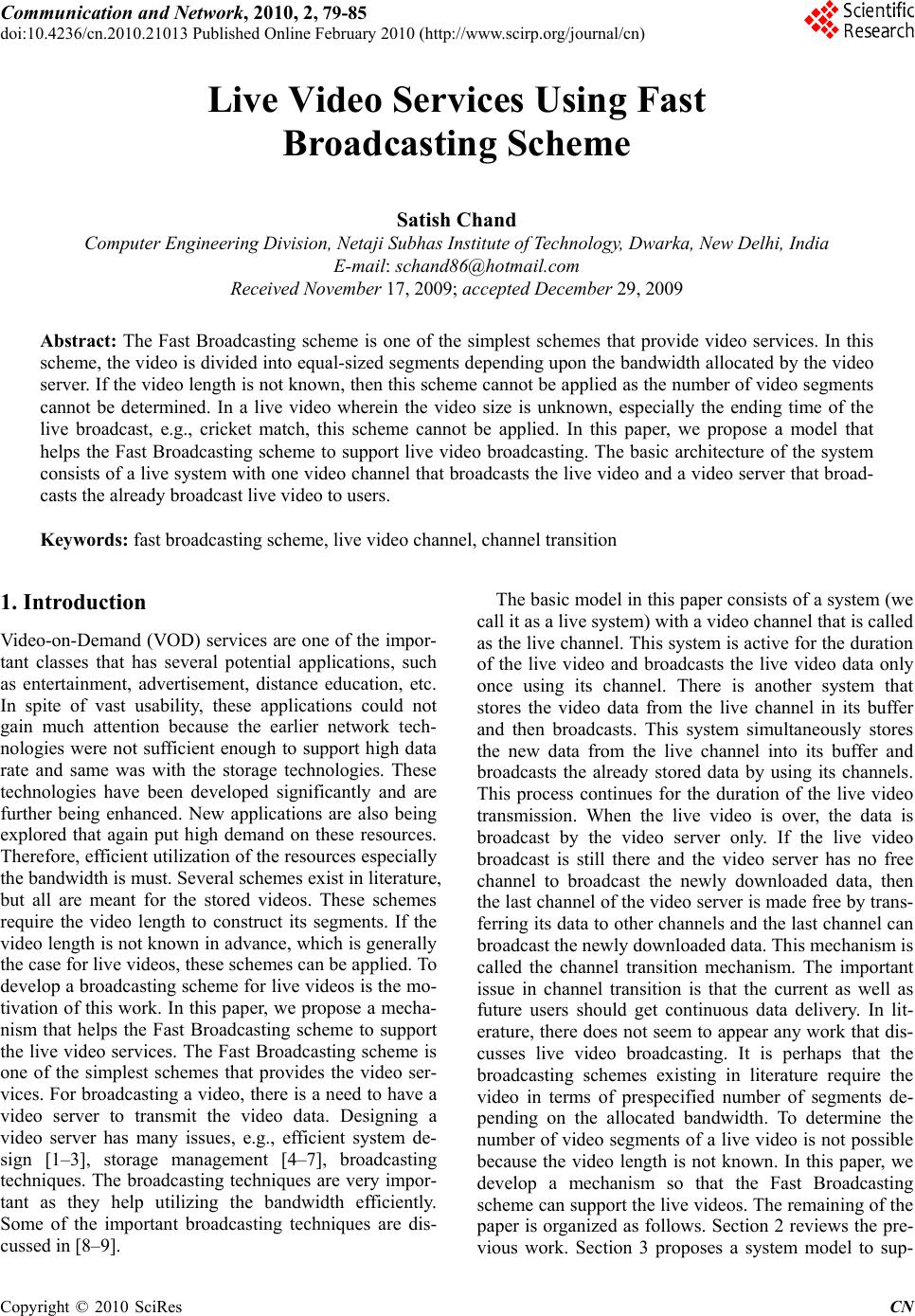 Communication and Network, 2010, 2, 79-85 doi:10.4236/cn.2010.21013 Published Online February 2010 (http://www.scirp.org/journal/cn) Copyright © 2010 SciRes CN 79 Live Video Services Using Fast Broadcasting Scheme Satish Chand Computer Engineering Division, Netaji Subhas Institute of Technology, Dwarka, New Delhi, India E-mail: schand86@hotmail.com Received November 17, 2009; accepted December 29, 2009 Abstract: The Fast Broadcasting scheme is one of the simplest schemes that provide video services. In this scheme, the video is divided into equal-sized segments depending upon the bandwidth allocated by the video server. If the video length is not known, then this scheme cannot be applied as the number of video segments cannot be determined. In a live video wherein the video size is unknown, especially the ending time of the live broadcast, e.g., cricket match, this scheme cannot be applied. In this paper, we propose a model that helps the Fast Broadcasting scheme to support live video broadcasting. The basic architecture of the system consists of a live system with one video channel that broadcasts the live video and a video server that broad- casts the already broadcast live video to users. Keywords: fast broadcasting scheme, live video channel, channel transition 1. Introduction Video-on-Demand (VOD) services are one of the impor- tant classes that has several potential applications, such as entertainment, advertisement, distance education, etc. In spite of vast usability, these applications could not gain much attention because the earlier network tech- nologies were not sufficient enough to support high data rate and same was with the storage technologies. These technologies have been developed significantly and are further being enhanced. New applications are also being explored that again put high demand on these resources. Therefore, efficient utilization of the resources especially the bandwidth is must. Several schemes exist in literature, but all are meant for the stored videos. These schemes require the video length to construct its segments. If the video length is not known in advance, which is generally the case for live videos, these schemes can be applied. To develop a broadcasting scheme for live videos is the mo- tivation of this work. In this paper, we propose a mecha- nism that helps the Fast Broadcasting scheme to support the live video services. The Fast Broadcasting scheme is one of the simplest schemes that provides the video ser- vices. For broadcasting a video, there is a need to have a video server to transmit the video data. Designing a video server has many issues, e.g., efficient system de- sign [1–3], storage management [4–7], broadcasting techniques. The broadcasting techniques are very impor- tant as they help utilizing the bandwidth efficiently. Some of the important broadcasting techniques are dis- cussed in [8–9]. The basic model in this paper consists of a system (we call it as a live system) with a video channel that is called as the live channel. This system is active for the duration of the live video and broadcasts the live video data only once using its channel. There is another system that stores the video data from the live channel in its buffer and then broadcasts. This system simultaneously stores the new data from the live channel into its buffer and broadcasts the already stored data by using its channels. This process continues for the duration of the live video transmission. When the live video is over, the data is broadcast by the video server only. If the live video broadcast is still there and the video server has no free channel to broadcast the newly downloaded data, then the last channel of the video server is made free by trans- ferring its data to other channels and the last channel can broadcast the newly downloaded data. This mechanism is called the channel transition mechanism. The important issue in channel transition is that the current as well as future users should get continuous data delivery. In lit- erature, there does not seem to appear any work that dis- cusses live video broadcasting. It is perhaps that the broadcasting schemes existing in literature require the video in terms of prespecified number of segments de- pending on the allocated bandwidth. To determine the number of video segments of a live video is not possible because the video length is not known. In this paper, we develop a mechanism so that the Fast Broadcasting scheme can support the live videos. The remaining of the paper is organized as follows. Section 2 reviews the pre- vious work. Section 3 proposes a system model to sup- 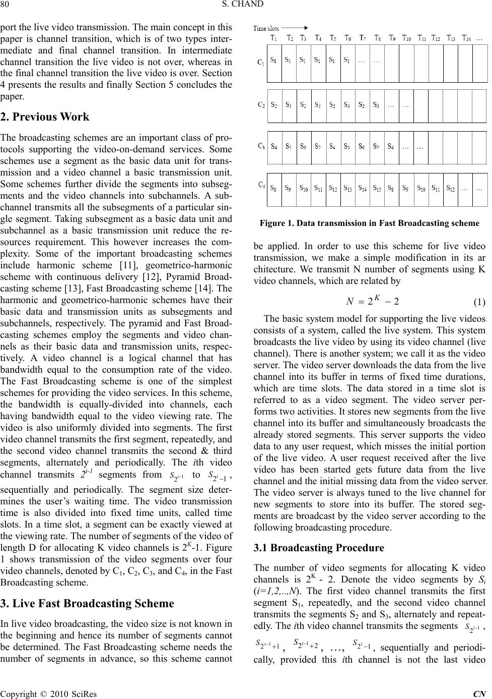 S. CHAND Copyright © 2010 SciRes CN 80 port the live video transmission. The main concept in this paper is channel transition, which is of two types inter- mediate and final channel transition. In intermediate channel transition the live video is not over, whereas in the final channel transition the live video is over. Section 4 presents the results and finally Section 5 concludes the paper. 2. Previous Work The broadcasting schemes are an important class of pro- tocols supporting the video-on-demand services. Some schemes use a segment as the basic data unit for trans- mission and a video channel a basic transmission unit. Some schemes further divide the segments into subseg- ments and the video channels into subchannels. A sub- channel transmits all the subsegments of a particular sin- gle segment. Taking subsegment as a basic data unit and subchannel as a basic transmission unit reduce the re- sources requirement. This however increases the com- plexity. Some of the important broadcasting schemes include harmonic scheme [11], geometrico-harmonic scheme with continuous delivery [12], Pyramid Broad- casting scheme [13], Fast Broadcasting scheme [14]. The harmonic and geometrico-harmonic schemes have their basic data and transmission units as subsegments and subchannels, respectively. The pyramid and Fast Broad- casting schemes employ the segments and video chan- nels as their basic data and transmission units, respec- tively. A video channel is a logical channel that has bandwidth equal to the consumption rate of the video. The Fast Broadcasting scheme is one of the simplest schemes for providing the video services. In this scheme, the bandwidth is equally-divided into channels, each having bandwidth equal to the video viewing rate. The video is also uniformly divided into segments. The first video channel transmits the first segment, repeatedly, and the second video channel transmits the second & third segments, alternately and periodically. The ith video channel transmits 2i-1 segments from 1 2i S to 21 i S , sequentially and periodically. The segment size deter- mines the user’s waiting time. The video transmission time is also divided into fixed time units, called time slots. In a time slot, a segment can be exactly viewed at the viewing rate. The number of segments of the video of length D for allocating K video channels is 2K-1. Figure 1 shows transmission of the video segments over four video channels, denoted by C1, C2, C3, and C4, in the Fast Broadcasting scheme. 3. Live Fast Broadcasting Scheme In live video broadcasting, the video size is not known in the beginning and hence its number of segments cannot be determined. The Fast Broadcasting scheme needs the number of segments in advance, so this scheme cannot Figure 1. Data transmission in Fast Broadcasting scheme be applied. In order to use this scheme for live video transmission, we make a simple modification in its ar chitecture. We transmit N number of segments using K video channels, which are related by 22 K N (1) The basic system model for supporting the live videos consists of a system, called the live system. This system broadcasts the live video by using its video channel (live channel). There is another system; we call it as the video server. The video server downloads the data from the live channel into its buffer in terms of fixed time durations, which are time slots. The data stored in a time slot is referred to as a video segment. The video server per- forms two activities. It stores new segments from the live channel into its buffer and simultaneously broadcasts the already stored segments. This server supports the video data to any user request, which misses the initial portion of the live video. A user request received after the live video has been started gets future data from the live channel and the initial missing data from the video server. The video server is always tuned to the live channel for new segments to store into its buffer. The stored seg- ments are broadcast by the video server according to the following broadcasting procedure. 3.1 Broadcasting Procedure The number of video segments for allocating K video channels is 2K - 2. Denote the video segments by Si (i=1,2,..,N). The first video channel transmits the first segment S1, repeatedly, and the second video channel transmits the segments S2 and S3, alternately and repeat- edly. The ith video channel transmits the segments 1 2i S , 1 21 i S , 1 22 i S , …, 21 i S , sequentially and periodi- cally, provided this ith channel is not the last video 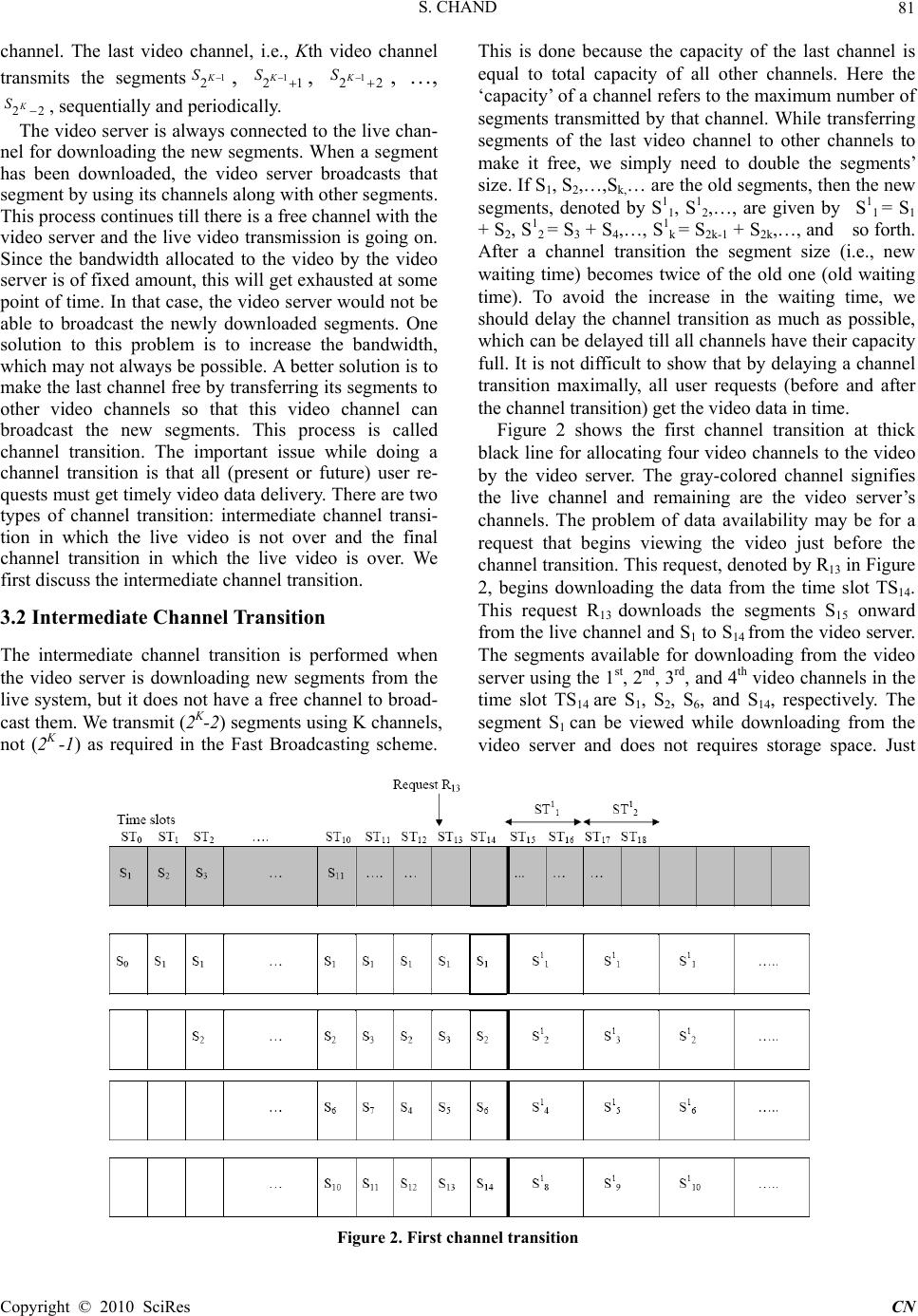 S. CHAND Copyright © 2010 SciRes CN 81 channel. The last video channel, i.e., Kth video channel transmits the segments1 2K S, 1 21 K S, 1 22 K S , …, 22 K S, sequentially and periodically. The video server is always connected to the live chan- nel for downloading the new segments. When a segment has been downloaded, the video server broadcasts that segment by using its channels along with other segments. This process continues till there is a free channel with the video server and the live video transmission is going on. Since the bandwidth allocated to the video by the video server is of fixed amount, this will get exhausted at some point of time. In that case, the video server would not be able to broadcast the newly downloaded segments. One solution to this problem is to increase the bandwidth, which may not always be possible. A better solution is to make the last channel free by transferring its segments to other video channels so that this video channel can broadcast the new segments. This process is called channel transition. The important issue while doing a channel transition is that all (present or future) user re- quests must get timely video data delivery. There are two types of channel transition: intermediate channel transi- tion in which the live video is not over and the final channel transition in which the live video is over. We first discuss the intermediate channel transition. 3.2 Intermediate Channel Transition The intermediate channel transition is performed when the video server is downloading new segments from the live system, but it does not have a free channel to broad- cast them. We transmit (2K-2) segments using K channels, not (2K -1) as required in the Fast Broadcasting scheme. This is done because the capacity of the last channel is equal to total capacity of all other channels. Here the ‘capacity’ of a channel refers to the maximum number of segments transmitted by that channel. While transferring segments of the last video channel to other channels to make it free, we simply need to double the segments’ size. If S1, S2,…,Sk,… are the old segments, then the new segments, denoted by S1 1, S1 2,…, are given by S1 1 = S1 + S2, S1 2 = S3 + S4,…, S1 k = S2k-1 + S2k,…, and so forth. After a channel transition the segment size (i.e., new waiting time) becomes twice of the old one (old waiting time). To avoid the increase in the waiting time, we should delay the channel transition as much as possible, which can be delayed till all channels have their capacity full. It is not difficult to show that by delaying a channel transition maximally, all user requests (before and after the channel transition) get the video data in time. Figure 2 shows the first channel transition at thick black line for allocating four video channels to the video by the video server. The gray-colored channel signifies the live channel and remaining are the video server’s channels. The problem of data availability may be for a request that begins viewing the video just before the channel transition. This request, denoted by R13 in Figure 2, begins downloading the data from the time slot TS14. This request R13 downloads the segments S15 onward from the live channel and S1 to S14 from the video server. The segments available for downloading from the video server using the 1st, 2nd, 3rd, and 4th video channels in the time slot TS14 are S1, S2, S6, and S14, respectively. The segment S1 can be viewed while downloading from the video server and does not requires storage space. Just Figure 2. First channel transition  S. CHAND Copyright © 2010 SciRes CN 82 Figure 3. Final channel transition after the channel transition, R13 needs the segment S2 for viewing and it is already in its buffer because it had been stored just before the channel transition. After viewing S2, R13 needs S3 segment which is the first half part of the second segment S1 2 (=S3 + S4) transmitted by the second channel after channel transition. Thus, the data of the segment S3 can be made available to R13. Using similar discussions, we can show that a request received in any time slot can receive timely video data. We now discuss the final channel transition. 3.3 Final Channel Transition In order to carry out the final channel transition, the video size must be known and it is possible only when the live video transmission is over. Since the video size is known, we can construct the video segments. The live video can be over at any point of time. If the data broad- cast by the live channel does not form a complete seg- ment, we can add dummy data to make it a complete segment. The live video can be over in any time slot, which means that the last video channel can have any number of segments ranging from one to its maximum capacity. If its capacity is full, then nothing is required to do. To carry out the final channel transition, the last channel must have at least one segment and at least one empty time slot. To occupy empty time slots with the video data, we need to increase the number of segment to (2K - 2) so that all time slots of all the video channels K are occupied. Increasing the number of segments de- creases the segment size as the video size is of fixed length. The first channel C1 transmits S1 ℓ-1 and the second channel C2 transmits the segments S2 ℓ-1 and S3 ℓ-1 just be- fore the final transition. Here the superscript ℓ of a seg- ment (time slot) signifies the segment (time slot) after the final (last) channel transition and (ℓ-1) for a segment (time slot) just before the final channel transition. After the final channel transition, the segment size decreases, i.e., some last portion of S1 ℓ-1 segment is added to the beginning of S2 ℓ-1 and some last portion S2 ℓ-1 is added to the beginning of S3 ℓ-1, and so forth. The number of new segments is (2K - 2) and they can occupy all the time slots on all channels. While carrying out this process, timely video data delivery to the current as well as future requests must be ensured. We now discuss how the video data delivery can be timely maintained to all user requests by taking an ex- ample. Consider that the video server has allocated four video channels to the video. The last (i.e., fourth) video channel can accommodate the segments S8, S9,…, S14. The live video can be over in any time slot STi ℓ-1 (7<i<14). Let i=8, i.e., the last video channel has to transmit the last segment as S9 ℓ-1 in the time slot ST8 ℓ-1. The segment S9 ℓ-1 will be available at the video server for transmission in the time slot ST9 ℓ-1 (refer Figure 3). We can carry out the channel transition immediately after the time slot ST9 ℓ-1. The request R8 that begins to download the data from the time slot ST9 ℓ-1 onward can download, if required, the segments S 1 ℓ-1, S3 ℓ-1, S5 ℓ-1, and S9 ℓ-1 in that time slot (refer Figure 3). The segment S1 ℓ-1 is viewed while downloading in the time slot ST9 ℓ-1 and in the next time slot (i.e., after channel transition) this re- quest needs S2 ℓ-1. The segment S2 ℓ-1 is distributed among the segments S2 ℓ and S3 ℓ after the channel transition. The segment S2 ℓ is available for downloading just after the channel transition, but the initial portion of segment S2 ℓ comprises some last portion of S1 ℓ-1 and the remaining is some initial portion of the segment S2 ℓ-1. It means that just after channel transition the initial portion of S2 ℓ that 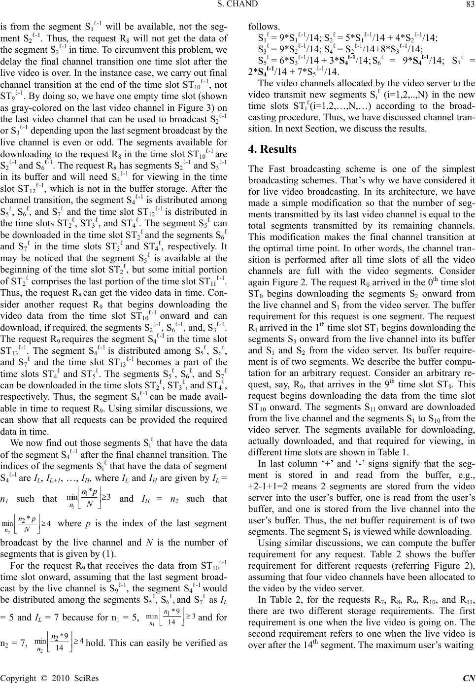 S. CHAND Copyright © 2010 SciRes CN 83 is from the segment S1 ℓ-1 will be available, not the seg- ment S2 ℓ-1. Thus, the request R8 will not get the data of the segment S2 ℓ-1 in time. To circumvent this problem, we delay the final channel transition one time slot after the live video is over. In the instance case, we carry out final channel transition at the end of the time slot ST10 ℓ-1, not ST9 ℓ-1. By doing so, we have one empty time slot (shown as gray-colored on the last video channel in Figure 3) on the last video channel that can be used to broadcast S2 ℓ-1 or S3 ℓ-1 depending upon the last segment broadcast by the live channel is even or odd. The segments available for downloading to the request R8 in the time slot ST10 ℓ-1 are S2 ℓ-1 and S6 ℓ-1. The request R8 has segments S2 ℓ-1 and S3 ℓ-1 in its buffer and will need S4 ℓ-1 for viewing in the time slot ST12 ℓ-1, which is not in the buffer storage. After the channel transition, the segment S4 ℓ-1 is distributed among S5 ℓ, S6 ℓ, and S7 ℓ and the time slot ST12 ℓ-1 is distributed in the time slots ST2 ℓ, ST3 ℓ, and ST4 ℓ. The segment S5 ℓ can be downloaded in the time slot ST2 ℓ and the segments S6 ℓ and S7 ℓ in the time slots ST3 ℓ and ST4 ℓ, respectively. It may be noticed that the segment S5 ℓ is available at the beginning of the time slot ST2 ℓ, but some initial portion of ST2 ℓ comprises the last portion of the time slot ST11 ℓ-1. Thus, the request R8 can get the video data in time. Con- sider another request R9 that begins downloading the video data from the time slot ST10 ℓ-1 onward and can download, if required, the segments S2 ℓ-1, S6 ℓ-1, and, S3 ℓ-1. The request R9 requires the segment S4 ℓ-1 in the time slot ST13 ℓ-1. The segment S4 ℓ-1 is distributed among S5 ℓ, S6 ℓ, and S7 ℓ and the time slot ST13 ℓ-1 becomes a part of the time slots ST4 ℓ and ST5 ℓ. The segments S5 ℓ, S6 ℓ, and S7 ℓ can be downloaded in the time slots ST2 ℓ, ST3 ℓ, and ST4 ℓ, respectively. Thus, the segment S4 ℓ-1 can be made avail- able in time to request R9. Using similar discussions, we can show that all requests can be provided the required data in time. We now find out those segments Si ℓ that have the data of the segment S4 ℓ-1 after the final channel transition. The indices of the segments Si ℓ that have the data of segment S4 ℓ-1 are IL, IL+1, …, IH, where IL and IH are given by IL = n1 such that 1 1* mi n3 n np N and IH = n2 such that 2 2* min 4 n np N where p is the index of the last segment broadcast by the live channel and N is the number of segments that is given by (1). For the request R9 that receives the data from ST10 ℓ-1 time slot onward, assuming that the last segment broad- cast by the live channel is S9 ℓ-1, the segment S4 ℓ-1 would be distributed among the segments S5 ℓ, S6 ℓ, and S7 ℓ as IL = 5 and IL = 7 because for n1 = 5, 1 1*9 min 3 14 n n and for n2 = 7, 2 2*9 min4 14 n n hold. This can easily be verified as follows. S1 ℓ = 9*S1 ℓ-1/14; S2 ℓ = 5*S1 ℓ-1/14 + 4*S2 ℓ-1/14; S3 ℓ = 9*S2 ℓ-1/14; S4 ℓ = S2 ℓ-1/14+8*S3 ℓ-1/14; S5 ℓ = 6*S3 ℓ-1/14 + 3*S4 ℓ-1/14; S6 ℓ = 9*S4 ℓ-1/14; S7 ℓ = 2*S4 ℓ-1/14 + 7*S5 ℓ-1/14. The video channels allocated by the video server to the video transmit new segments Si ℓ (i=1,2,..,N) in the new time slots STi ℓ(i=1,2,…,N,…) according to the broad- casting procedure. Thus, we have discussed channel tran- sition. In next Section, we discuss the results. 4. Results The Fast broadcasting scheme is one of the simplest broadcasting schemes. That’s why we have considered it for live video broadcasting. In its architecture, we have made a simple modification so that the number of seg- ments transmitted by its last video channel is equal to the total segments transmitted by its remaining channels. This modification makes the final channel transition at the optimal time point. In other words, the channel tran- sition is performed after all time slots of all the video channels are full with the video segments. Consider again Figure 2. The request R0 arrived in the 0th time slot ST0 begins downloading the segments S2 onward from the live channel and S1 from the video server. The buffer requirement for this request is one segment. The request R1 arrived in the 1th time slot ST1 begins downloading the segments S3 onward from the live channel into its buffer and S1 and S2 from the video server. Its buffer require- ment is of two segments. We describe the buffer compu- tation for an arbitrary request. Consider an arbitrary re- quest, say, R9, that arrives in the 9th time slot ST9. This request begins downloading the data from the time slot ST10 onward. The segments S11 onward are downloaded from the live channel and the segments S1 to S10 from the video server. The segments available for downloading, actually downloaded, and that required for viewing, in different time slots are shown in Table 1. In last column ‘+’ and ‘-’ signs signify that the seg- ment is stored in and read from the buffer, e.g., +2-1+1=2 means 2 segments are stored from the video server into the user’s buffer, one is read from the user’s buffer, and one is stored from the live channel into the user’s buffer. Thus, the net buffer requirement is of two segments. The segment S1 is viewed while downloading. Using similar discussions, we can compute the buffer requirement for any request. Table 2 shows the buffer requirement for different requests (referring Figure 2), assuming that four video channels have been allocated to the video by the video server. In Table 2, for the requests R7, R8, R9, R10, and R11, there are two different storage requirements. The first requirement is one when the live video is going on. The second requirement refers to one when the live video is over after the 14th segment. The maximum user’s waiting 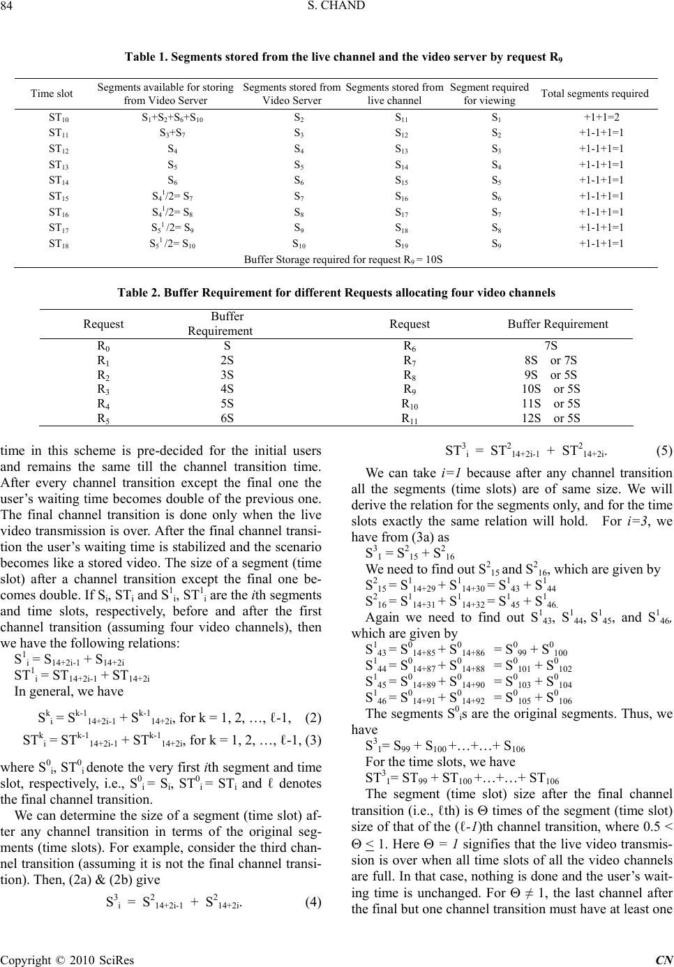 S. CHAND Copyright © 2010 SciRes CN 84 Table 1. Segments stored from the live channel and the video server by request R9 Time slot Segments available for storing from Video Server Segments stored from Video Server Segments stored from live channel Segment required for viewing Total segments required ST10 S 1+S2+S6+S10 S 2 S 11 S 1 +1+1=2 ST11 S 3+S7 S 3 S 12 S 2 +1-1+1=1 ST12 S 4 S 4 S 13 S 3 +1-1+1=1 ST13 S 5 S 5 S 14 S 4 +1-1+1=1 ST14 S 6 S 6 S 15 S 5 +1-1+1=1 ST15 S 41/2= S7 S 7 S 16 S 6 +1-1+1=1 ST16 S 41/2= S8 S 8 S 17 S 7 +1-1+1=1 ST17 S 51 /2= S9 S 9 S 18 S 8 +1-1+1=1 ST18 S 51 /2= S10 S 10 S 19 S 9 +1-1+1=1 Buffer Storage required for request R9 = 10S Table 2. Buffer Requirement for different Requests allocating four video channels Request Buffer Requirement Request Buffer Requirement R0 S R6 7S R1 2S R7 8S or 7S R2 3S R8 9S or 5S R3 4S R9 10S or 5S R4 5S R10 11S or 5S R5 6S R11 12S or 5S time in this scheme is pre-decided for the initial users and remains the same till the channel transition time. After every channel transition except the final one the user’s waiting time becomes double of the previous one. The final channel transition is done only when the live video transmission is over. After the final channel transi- tion the user’s waiting time is stabilized and the scenario becomes like a stored video. The size of a segment (time slot) after a channel transition except the final one be- comes double. If Si, STi and S1 i, ST1 i are the ith segments and time slots, respectively, before and after the first channel transition (assuming four video channels), then we have the following relations: S1 i = S14+2i-1 + S14+2i ST1 i = ST14+2i-1 + ST14+2i In general, we have Sk i = Sk-1 14+2i-1 + Sk-1 14+2i, for k = 1, 2, …, ℓ-1, (2) STk i = STk-1 14+2i-1 + STk-1 14+2i, for k = 1, 2, …, ℓ-1, (3) where S0 i, ST0 i denote the very first ith segment and time slot, respectively, i.e., S0 i = Si, ST0 i = STi and ℓ denotes the final channel transition. We can determine the size of a segment (time slot) af- ter any channel transition in terms of the original seg- ments (time slots). For example, consider the third chan- nel transition (assuming it is not the final channel transi- tion). Then, (2a) & (2b) give S3 i = S2 14+2i-1 + S2 14+2i. (4) ST3 i = ST2 14+2i-1 + ST2 14+2i. (5) We can take i=1 because after any channel transition all the segments (time slots) are of same size. We will derive the relation for the segments only, and for the time slots exactly the same relation will hold. For i=3, we have from (3a) as S3 1 = S2 15 + S2 16 We need to find out S2 15 and S2 16, which are given by S2 15 = S1 14+29 + S1 14+30 = S1 43 + S1 44 S2 16 = S1 14+31 + S1 14+32 = S1 45 + S1 46. Again we need to find out S1 43, S1 44, S1 45, and S1 46, which are given by S1 43 = S0 14+85 + S0 14+86 = S0 99 + S0 100 S1 44 = S0 14+87 + S0 14+88 = S0 101 + S0 102 S1 45 = S0 14+89 + S0 14+90 = S0 103 + S0 104 S1 46 = S0 14+91 + S0 14+92 = S0 105 + S0 106 The segments S0 is are the original segments. Thus, we have S3 1= S99 + S100 +…+…+ S106 For the time slots, we have ST3 1= ST99 + ST100 +…+…+ ST106 The segment (time slot) size after the final channel transition (i.e., ℓth) is times of the segment (time slot) size of that of the (ℓ-1)th channel transition, where 0.5 < < 1. Here = 1 signifies that the live video transmis- sion is over when all time slots of all the video channels are full. In that case, nothing is done and the user’s wait- ing time is unchanged. For ≠ 1, the last channel after the final but one channel transition must have at least one  S. CHAND Copyright © 2010 SciRes CN 85 segment and at least one empty time slot. Consider that the last video channel has NS segments after the final but one channel transition. After the final channel transition, the segment size would be (2K-1 + NS)*Sℓ-1/N. For K=4, N=14, and NS=2, the segment size after the final channel transition is (23 + 2)*Sℓ-1/ 14=10*Sℓ-1/14. The user’s waiting time changes after a channel transi- tion depending upon the segment size and this is fixed for the stored videos for a given bandwidth. In the pro- posed scheme, the initial user’s waiting time is decided by the service provider and it is also equal to the segment size. This decision is necessary for arranging the video data that would be downloaded in terms of the segments and made on the basis of bandwidth allocated to the video. The video size increases after a new segment from the live channel has been downloaded, but this change affects broadcasting only after the channel transition. After the final channel transition, the user’s waiting time generally decreases. The basic requirement to carry out the final channel transition is that there must be at least one segment and at least one empty time slot on the last video channel. 5. Conclusions In this paper, we have proposed a technique so that the Fast Broadcasting scheme can be used for broadcasting the live videos. The Fast Broadcasting scheme does not support the live video services in its original form be- cause it requires the number of segments of the video beforehand and for that the video length should be known, which is generally not known in advance in case of the live videos. In this proposed scheme, the live video data is stored in buffer at the video server in terms of fixed time durations, called time slots. The data downloaded in a time slot is considered as a segment. The downloaded segments are broadcast by the video server till there is free channel available with the video server. When no free channel is available and live video is there, channel transition is required. In the proposed scheme, the channel transition can be delayed maximally, i.e., up to the point when all time slots of all the video channels have been completely occupied. This study may be useful for designing a VOD system that can support the live video, such as cricket match, interactive educa- tion session, etc. REFERENCES [1] K. M. Ho and K. T. Lo, “Design of a decentralized video- on-demand system with cooperative clients in multicast environment,” Advances in Multimedia Information Pr- ocessing, Lecture Notes Computer Science, 4810, pp. 401–404, 2007. [2] Y. B. L. Jack, “Channel folding – an algorithm to improve efficiency of multicast video-on-demand systems,” IEEE Transactions on Multimedia, Vol. 7, No. 2, pp. 366–378, 2005. [3] W. F. Poon, K. T. Lo, and J. Feng, “A hierarchical video-on-demand system with double-rate batching,” JVCIR, Vol. 16, No. 1, pp. 1–18, 2005. [4] D. J. Gemmell, H. M. Vin, D. Kandlur, P. V. Rangan, and L. A. Rowe, “Multimedia storage servers: a tutorial,” Computer, Vol. 28, No. 5, pp. 40–49, 1995. [5] N. J. Sarhan and C. R. Das, “Caching and scheduling in nad based multimedia servers,” IEEE Transactions on Parallel and Distributed Systems, Vol. 5, No. 10, pp. 921–933, 2004. [6] A. L. Chervnak, D. A. Patterson and R. H. Katz, “Choos- ing the best storage system for video service,” In Pro- ceeding of third ACM international conference on Mul- timedia, San Francisco, USA, pp. 109–119, 1995. [7] A. Dan and D. Sitaram, “Buffer management policy for an on-demand video server,” IBM Watson Research Cen- ter, RC 19347, 1994. [8] C. C. Aggarwal, J. L. Wolf, and P. S. Yu, “A permutation based pyramid broadcasting scheme for video on demand systems,” In Proceeding International Conference on Multimedia Computing and Systems, pp. 118–126, 1996. [9] L. Gao, J. Kurose, and D. Towsley, “Efficient schemes for broadcasting popular videos,” In Proceeding of NOSS- DAV’98, pp. 183–194, 1998. [10] A. L. N. Reddy, J. Wyllie, and K. B. R. Wijayratne, “Disk scheduling in a multimedia I/O system,” ACM Transac- tions on Computer Communication and Application (TOMCCAP), Vol. 1, No. 1, pp. 37–59, 2005. [11] L. S. Juhn and L. M. Tseng, “Harmonic broadcasting scheme for video-on-demand service,” IEEE Transactions on Consumer Electronics, Vol. 43, No. 3, pp. 268–271, 1997. [12] H. Om and S. Chand, “Geometrico-harmonic broadcast- ing scheme with continuous redundancy,” IEEE Transac- tions on Multimedia, Vol. 9, No. 1, pp. 410–419, 2007. [13] S. Viswanathan and T. Imielinski, “Metropolitan area video-on-demand service using pyramid broadcasting,” ACM Multimedia System, Vol. 4, No. 4, pp. 197–208, 1996. [14] L. S. Juhn and L. M. Tseng, “Fast data broadcasting and receiving scheme for popular video service,” IEEE Trans- actions on Broadcasting, Vol. 44, No. 1, pp. 100–105, 1998. |