Paper Menu >>
Journal Menu >>
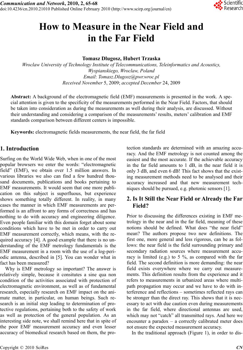 Communication and Network, 2010, 2, 65-68 doi:10.4236/cn.2010.21010 Published Online February 2010 (http://www.scirp.org/journal/cn) Copyright © 2010 SciRes CN 65 How to Measure in the Near Field and in the Far Field Tomasz Dlugosz, Hubert Trzaska Wroclaw University of Technology Institute of Telecommunications, Teleinformatics and Acoustics, Wyspianskiego, Wroclaw, Poland Email: Tomasz.Dlugosz@pwr.wroc.pl Received November 5, 2009; accepted December 24, 2009 Abstract: A background of the electromagnetic field (EMF) measurements is presented in the work. A spe- cial attention is given to the specificity of the measurements performed in the Near Field. Factors, that should be taken into consideration as during the measurements as well during their analysis, are discussed. Without their understanding and considering a comparison of the measurements’ results, meters’ calibration and EMF standards comparison between different centers is impossible. Keywords: electromagnetic fields measurements, the near field, the far field 1. Introduction Surfing on the World Wide Web, when in one of the most popular browsers we enter the words: “electromagnetic field” (EMF), we obtain over 1.5 million answers. In various libraries we also can find a few hundred thou- sand documents, publications and books pertaining to EMF measurements. It would seem that one more publi- cation on this subject is superfluous, but experience shows something totally different. In reality, in many cases the manner in which EMF measurements are per- formed is an affront to any forms of correctness and has nothing to do with accuracy and engineering diligence. Even people familiar with this domain forget about some conditions which have to be met in order to carry out EMF measurement correctly, which means, with the re- quired accuracy [4]. A good example that there is no un- derstanding of the EMF metrology fundamentals is the EMF measurement in a room with the use of a log-peri- odic antenna, described in [5]. You can wonder what in fact has been measured? Why is EMF metrology so important? The answer is relatively simple, because it consitutes a sine qua non condition of the activities associated with protection of electromagnetic environment, as well as of fundamental research, especially research on EMF impact on the ani- mate matter, in particular, on human beings. Such re- search is an initial step leading to determination of pro- tective regulations, pertaining both to the safety of work as well as protection of the general population. As an interesting side note, we shall remind here that in spite of the poor EMF measurement accuracy and even lesser accuracy of biomedical research based on them, the pro- tection standards are determined with an amazing accu- racy. And the EMF metrology is not counted among the easiest and the most accurate. If the achievable accuracy in the far field amounts to 1 dB, in the near field it is only 3 dB, and even 6 dB! This fact shows that the exist- ing measurement methods need to be analysed and their accuracy increased and that new measurement tech- niques should be pursued, e.g. photonic sensors [1]. 2. Is It Still the Near Field or Already the Far Field? Prior to discussing the differences existing in EMF me- trology in the near and in the far field, meaning of these notions should be defined. What does “the near field” mean? The authors propose two new definitions. The first one, more general and less rigorous, can be as fol- lows: the near field is the field surrounding primary and secondary radiation sources where measurement accu- racy is limited (e.g.) to 5 %, as compared with the far field. The second definition is more demanding: the near field exists everywhere where we carry out measure- ments. This definition results from the experience and it refers to measurements in urbanized areas where multi- path propagation may occur and we have to do with in- terference and reflections – sometimes reflected rays can be stronger than the direct ray. This shows that it is nec- essary to act with due caution even during measurements in the far field, where directional antennas are used, which may not “catch” all transmitted rays. And here we encounter a paradox – a correctly calibrated meter does not ensure the expected measurement accuracy. In the traditional approach (Figure 1), in order to dis-  T. DLUGOSZ ET AL. Copyright © 2010 SciRes CN 66 Figure 1. Near and Far Field around an antenna tinguish the specificity of measurements in the near field and in the far field, a criterion was adopted which en- ables delimitation of these two areas, although there is no clearly defined and discrete boundary between the near field and the far field [8]. If D is adopted as the largest antenna size and the emitted wave length is designated, the boundary (R) be- tween the near zone and the far zone can be determined from the following relationship: 2 2D R (1) In order to demonstrate that the far zone can be the same for different types of antennas, operating on dif- ferent frequencies, two examples will be given (Trzaska, 2002): Example No. 1: For a parabolic antenna with 3 m dish diameter oper- ating on 10 GHz frequency the far field boundary is at 600 m, Example No. 2: For the antenna of the former transmission centre in Gąbin (Poland) having a height of 0.5 λ and operating on 227 kHz frequency the Far Field boundary is at 660 m. As you can see, the Far Field zone is not something assigned permanently to a given antenna operating on the preset frequency. As the above two examples show, the same far zone boundary exists for extremely different antennas. Also the Near Field can be a function of elec- trical size [2]. 3. Measured Quantities In the Near Field, the mutual relationship between elec- tric field (E) and magnetic field (H) components depends on the type of EMF source and on the distance between the source and the observation point. Therefore, deter- mination of one of them is not sufficient for computing the other. Situation is different in the case of the far field where knowledge of one of the field components, e.g. of elec- tric field vector – E, enables determination of the other (magnetic field vector – H), using the relationship in which these two quantities are interrelated by means of the impedance of free space (Z): HEn Z (2) In both cases, i.e. in the near and in the far field, when we know the E and H components, we are in a position to determine the power density. With this aim, the mean value of the Poynting vector (S) is determined: HES Re5.0 (3) In the Far Field metrology it is not necessary to carry out an additional measurement of quantities other than the E, H or S, contrary to the near field metrology in which the temperature increase and current density, caused by the EMF impact, are also measured. Measurement of the temperature increment (ΔT), re- sulting from the EMF impact, of a material which has a given specific heat (cw), makes it possible to determine the Specific Absorption Rate SAR: t Tc SAR w (4) The SAR is commonly used for examination of the EMF impact on human body. However, there are some limitations of its use, which are discussed in detail in [8]. In this paper we shall only note that the SAR parameter can be used for the frequencies higher than 300 MHz due to too small sensitivity. In the lower frequency ranges an essential parameter is the density of the current induced into tissues [7]. Knowing the conductivity (σ) of the ex- amined medium and the density value of electric field (E) existing in this medium, the current density (J) can be calculated: EJ (5) The manner of measurements of the current flowing through a human body is described in [7]. Often meas- urements of the currents flowing through legs or feet are presented, neglecting the currents appearing in other parts of the body, or unmeasurable eddy currents. For electric field measurements in the near field elec- trically-short dipole antennas are used, while magnetic field is measured by means of small frame antennas. In the far field directional antennas are used. An essential problem faced in EMF measurements, regardless of what sensor is used, is the sensor’s presence in the measured field, which causes deformation of this field and mutual interaction between the sensor and the neighbouring ma- terial objects. This interaction constitutes a serious factor affecting the measurement accuracy, both during EMF measurements and EMF sensor calibration, as well as in cases when we use exposure kits for examination of the  T. DLUGOSZ ET AL. Copyright © 2010 SciRes CN 67 features of any material object [6]. In the measurements polarization is also important. After all, the E, H and S vectors can have three spatial components each (quasi-ellipsoidal polarization caused, for example, by rotation of the polarization plane in space). In such a case isotropic sensors have to be used. 4. Measurement Accuracy Measurement accuracy constitutes the biggest problem in EMF measurements. For calibration of EMF meters, as well as for examination of equipment and matter sensi- tivity to EMF impact, EMFs of known parameters are used – standard EMFs. For generation of a standard EMF knowledge of not only the values of generated parame- ters is necessary, but also of the accuracies of their gen- eration. EMF standards are among the least accurate as compared with the standards of other physical quantities. Many of such quantities are determined with an accuracy of 10-10 % or higher, while the error of standard EMFs generation in renowned centres ranges from 5 % to 10 %. In other words, even before we commence field meas- urements, from the very beginning the measurement re- sult is burdened with an error which amounts to 5 % in the best case, and this is not all. The main factor which limits EMF measurement ac- curacy in the near field is the antenna dimensions. Point antennas would be the best to use, because otherwise an antenna causes averaging of the measured EMF values. Variations of the spatial field strength, resulting from either amplitude or phase variations, are subject to aver- aging. These variations depend on the curvature of the EMF field which surrounds the source [3,8]. Some ex- amples of error graphs, both amplitude and phase errors, are shown on Figures 2 and 3 (where: Ro – the distance between the source and the measuring antenna centre, α – an exponent characterizing field curvature, h – the length of dipole arm, k – propagation constant). The pre- sented curves refer to a dipole antenna but identical con- siderations are applicable to a frame antenna as well [8]. Passing over the impact of the meter used and of the person performing the measurements on the disturbances of the measured EMF, you should not forget the error Figure 2. Amplitude error δ A Figure 3. Phase error δ f which is contributed by the measuring person, which we shall call a “human factor”. This factor also depends on the conditions in which measurements are performed and its importance is essential, as it is shown in [4]. This fac- tor is described on the basis of two measurement series, performed by four persons in the same measuring points, by means of two meters: MEH-25 with 3AS-1 probe and PMM 8053A with EP-300 probe. This simple experiment has shown (see Table 1) how diversified the measure- ment results can be if the measurements are performed by different persons. Therefore, the “human factor” is a gross error but, unfortunately, it is not taken into account when measurement results are worked out. Table 1. “Human factor” measurement results [4] Series I Series II Position of measurements 1 2 3 4 Mean value δ(min-max) [%] 1 2 3 4 Mean value δ(min-max) [%] 1 14.9 16.5 17.6 15.5 16.1 8.3 16.6 15.8 14.2 16.9 15.9 8.7 2 17.6 16.2 18.5 19.0 17.8 8.0 16.5 16.5 19.2 18.5 17.7 7.6 3 9.2 7.3 6.6 8.8 8.0 16.5 5.8 8.8 8.2 6.1 7.2 20.5 4 9.1 8.2 10.2 8.2 8.9 10.9 9.6 10.4 9.9 8.6 9.6 9.5 5 9.9 10.2 11.6 11.0 10.7 7.9 11.0 10.4 14.0 10.4 11.5 14.8  T. DLUGOSZ ET AL. Copyright © 2010 SciRes CN 68 Table 2. Comparison of measurements in the near field and in the far field Parameter Near Field Far Field measured EMF component E, H & S E or H, and S on mwaves other magnitudes measurement I, T, (SA, SAR) “HESTIA” unnecessary spatial components 3 1 or 2 polarization quasi-ellipsoidal linear or elliptical environment complex, multipath propagation & inter- ference usually simple frequency spectrum wide, often unknown, many fringes usually single frequency antennas small, omnidirectional resonant, directional temporal & spatial EMF alternations significant usually negligible uncertainty 3, 6 or more dB around 1 dB temperature sensitivity significant unessential susceptibility significant ommitable influence of surroundings significant usually ommitable procedures complex simple agreement with theory reasonable good measured levels V/m, kV/m mV/m, mV/m 5. Summary The paper presents a comparative analysis of EMF me- trology in the near field and in the far field. Measure- ments in the near field are more difficult and burdened with a considerably larger error than measurements per- formed in the far field. As you can see there are many factors which have an impact on measurement accuracy and the selection of a measurement zone should involve proper selection of adequate tools and measurement techniques. It is not feasible to present all aspects of EMF meas- urements in the near field and in the far field. Due to practical limitations of this paper only most important aspects of this metrology are discussed herein, supple- mented by Table 2. REFERENCES [1] K. Abramski and H. Trzaska, “FM EMF Sensors,” 3rd International Symposium on Electromagnetic Compati- bility, Beijing, China, pp. 222–225, May 2002. [2] T. Adams, Y. Lewiatan, and K. S. Nordby, “Electromag- netic near fields as a function of electrical size,” IEEE Transaction on Electromagnetic Compatibility, Vol. 25, No. 4, pp. 428–432, 1983. [3] P. Bieńkowski and H. Trzaska, “Electromagnetic fields metrology,” National Symposium of Telecommunications, Bydgoszcz, Poland, pp. 167–178, September 1995. [4] P. Bieńkowski, H. Trzaska, “Interlaboratory comparisons in EMF survey measurement – methods and results,” In- ternational Conference and COST 281 Workshop on Emerging EMF-Technologies, Potential Sensitive Groups and Health, Graz, Austria, 20–21 April 2006, (CD pro- ceedings). [5] C. Bornkessel and M. Wuschek, “Exposure measure- ments in different WLAN – scenarios,” International Conference and COST 281 Workshop on Emerging EMF-Technologies, Potential Sensitive Groups and Health, Graz, Austria, 20–21 April 2006, (CD proceed- ings). [6] T. Dlugosz and H. Trzaska, “Proximity effects in EMF measurements and standards,” XXVIIIth General Assem- bly of International Union of Radio Science (URSI), 23–29 October 2005, New Delhi, India, (CD proceed- ings). [7] O. P. Gandhi, Y. Chen, and A. Riazi, “Currents induced in a human being for plane-wave exposure conditions 0-50 mhz and for RF sealers,” IEEE Transactions on Bio- medical Engineering, Vol. BME-33, No. 8, pp.757–767, 1986. [8] H. Trzaska, “EMF measurements in the near field,” Noble Publ. Co., 2002. [9] H. Trzaska, “Limitation in the SAR use,” The Environ- mentalist, Vol. 25, No. 2/4, pp. 81–185, 2005. |