Paper Menu >>
Journal Menu >>
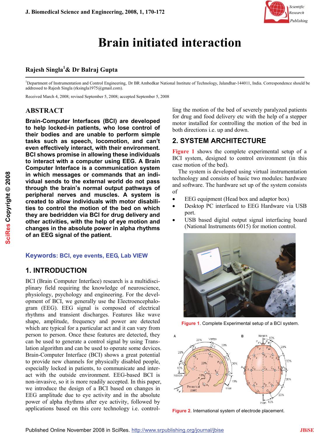
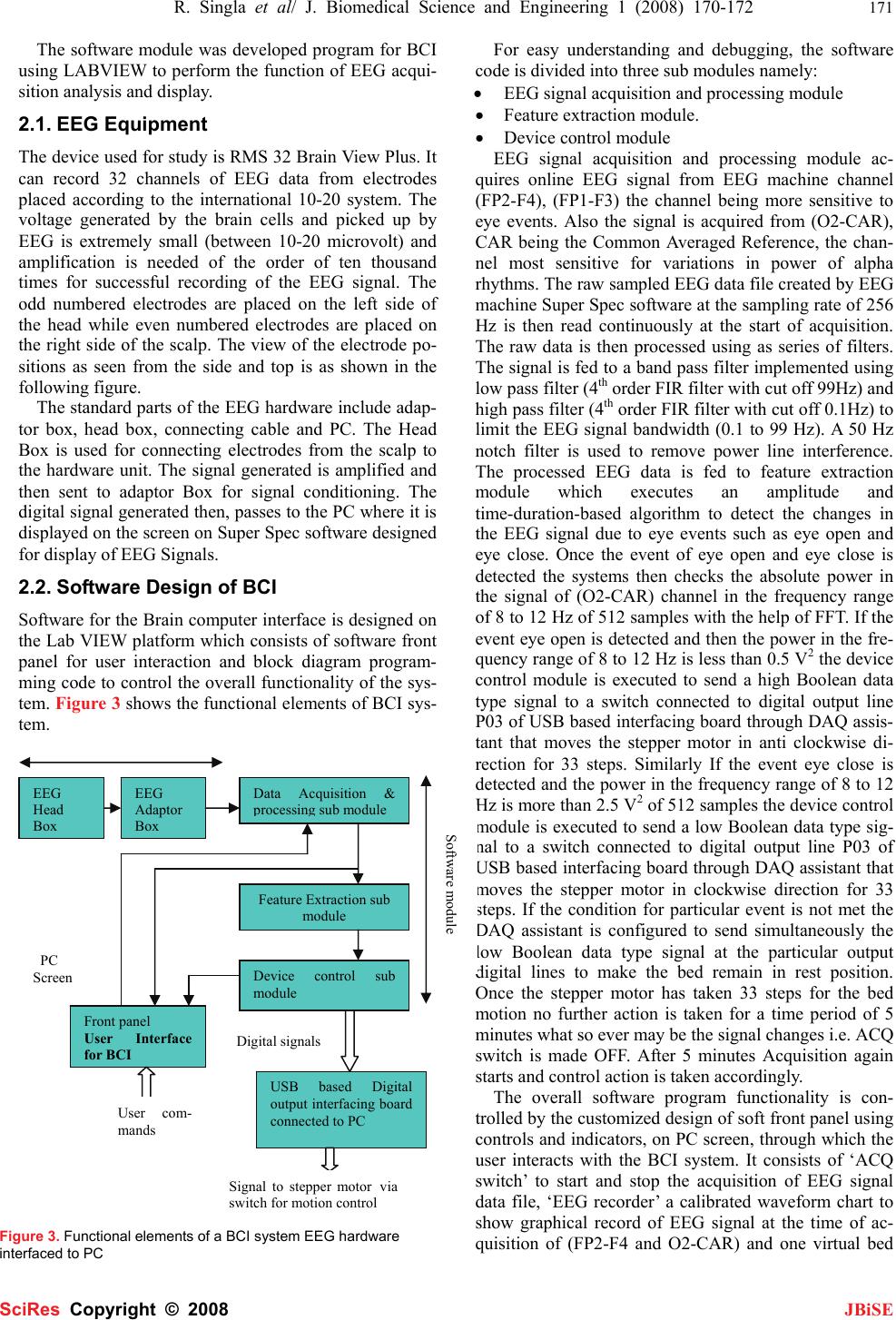
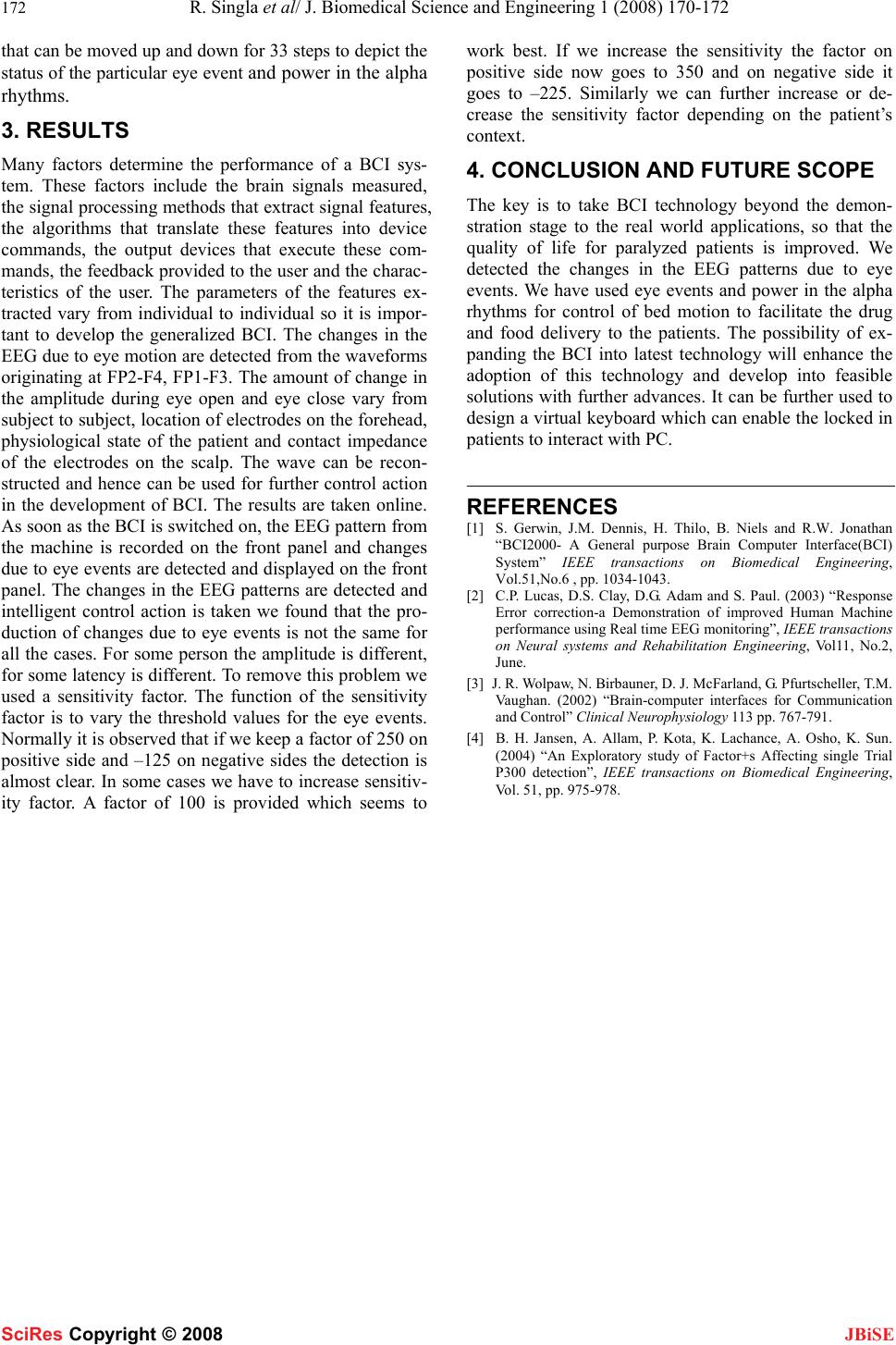
 J. Biomedical Science and Engineering, 2008, 1, 170-172 Published Online November 2008 in SciRes. http://www.srpublishing.org/journal/jbise JBiSE Brain initiated interaction Rajesh Singla1& Dr Balraj Gupta 1Department of Instrumentation and Control Engineering, Dr BR Ambedkar National Institute of Technology, Jalandhar-144011, India. Correspondence should be addressed to Rajesh Singla (rksingla1975@gmail.com). Received March 4, 2008; revised September 5, 2008; accepted September 5, 2008 ABSTRACT Brain-Computer Interfaces (BCI) are developed to help locked-in patients, who lose control of their bodies and are unable to perform simple tasks such as speech, locomotion, and can’t even effectively interact, with their environment. BCI shows promise in allowing these individuals to interact with a computer using EEG. A Brain Computer Interface is a communication system in which messages or commands that an indi- vidual sends to the external world do not pass through the brain’s normal output pathways of peripheral nerves and muscles. A system is created to allow individuals with motor disabili- ties to control the motion of the bed on which they are bedridden via BCI for drug delivery and other activities, with the help of eye motion and changes in the absolute power in alpha rhythms of an EEG signal of the patient. Keywords: BCI, eye events, EEG, Lab VIEW 1. INTRODUCTION BCI (Brain Computer Interface) research is a multidisci- plinary field requiring the knowledge of neuroscience, physiology, psychology and engineering. For the devel- opment of BCI, we generally use the Electroencephalo- gram (EEG). EEG signal is composed of electrical rhythms and transient discharges. Features like wave shape, amplitude, frequency and power are detected which are typical for a particular act and it can vary from person to person. Once these features are detected, they can be used to generate a control signal by using Trans- lation algorithm and can be used to operate some devices. Brain-Computer Interface (BCI) shows a great potential to provide new channels for physically disabled people, especially locked in patients, to communicate and inter- act with the outside environment. EEG-based BCI is non-invasive, so it is more readily accepted. In this paper, we introduce the design of a BCI based on changes in EEG amplitude due to eye activity and in the absolute power of alpha rhythms after eye activity, followed by applications based on this core technology i.e. control- ling the motion of the bed of severely paralyzed patients for drug and food delivery etc with the help of a stepper motor installed for controlling the motion of the bed in both directions i.e. up and down. 2. SYSTEM ARCHITECTURE Figure 1 shows the complete experimental setup of a BCI system, designed to control environment (in this case motion of the bed). The system is developed using virtual instrumentation technology and consists of basic two modules: hardware and software. The hardware set up of the system consists of • EEG equipment (Head box and adaptor box) • Desktop PC interfaced to EEG Hardware via USB port. • USB based digital output signal interfacing board (National Instruments 6015) for motion control. Figure 1. Complete Experimental setup of a BCI system. Figure 2. International system of electrode placement. SciRes Copyright © 2008  R. Singla et al/ J. Biomedical Science and Engineering 1 (2008) 170-172 171 SciRes Copyright © 2008 JBiSE The software module was developed program for BCI using LABVIEW to perform the function of EEG acqui- sition analysis and display. 2.1. EEG Equipment The device used for study is RMS 32 Brain View Plus. It can record 32 channels of EEG data from electrodes placed according to the international 10-20 system. The voltage generated by the brain cells and picked up by EEG is extremely small (between 10-20 microvolt) and amplification is needed of the order of ten thousand times for successful recording of the EEG signal. The odd numbered electrodes are placed on the left side of the head while even numbered electrodes are placed on the right side of the scalp. The view of the electrode po- sitions as seen from the side and top is as shown in the following figure. The standard parts of the EEG hardware include adap- tor box, head box, connecting cable and PC. The Head Box is used for connecting electrodes from the scalp to the hardware unit. The signal generated is amplified and then sent to adaptor Box for signal conditioning. The digital signal generated then, passes to the PC where it is displayed on the screen on Super Spec software designed for display of EEG Signals. 2.2. Software Design of BCI Software for the Brain computer interface is designed on the Lab VIEW platform which consists of software front panel for user interaction and block diagram program- ming code to control the overall functionality of the sys- tem. Figure 3 shows the functional elements of BCI sys- tem. Figure 3. Functional elements of a BCI system EEG hardware interfaced to PC For easy understanding and debugging, the software code is divided into three sub modules namely: • EEG signal acquisition and processing module • Feature extraction module. • Device control module EEG signal acquisition and processing module ac- quires online EEG signal from EEG machine channel (FP2-F4), (FP1-F3) the channel being more sensitive to eye events. Also the signal is acquired from (O2-CAR), CAR being the Common Averaged Reference, the chan- nel most sensitive for variations in power of alpha rhythms. The raw sampled EEG data file created by EEG machine Super Spec software at the sampling rate of 256 Hz is then read continuously at the start of acquisition. The raw data is then processed using as series of filters. The signal is fed to a band pass filter implemented using low pass filter (4th order FIR filter with cut off 99Hz) and high pass filter (4th order FIR filter with cut off 0.1Hz) to limit the EEG signal bandwidth (0.1 to 99 Hz). A 50 Hz notch filter is used to remove power line interference. The processed EEG data is fed to feature extraction module which executes an amplitude and time-duration-based algorithm to detect the changes in the EEG signal due to eye events such as eye open and eye close. Once the event of eye open and eye close is detected the systems then checks the absolute power in the signal of (O2-CAR) channel in the frequency range of 8 to 12 Hz of 512 samples with the help of FFT. If the event eye open is detected and then the power in the fre- quency range of 8 to 12 Hz is less than 0.5 V2 the device control module is executed to send a high Boolean data type signal to a switch connected to digital output line P03 of USB based interfacing board through DAQ assis- tant that moves the stepper motor in anti clockwise di- rection for 33 steps. Similarly If the event eye close is detected and the power in the frequency range of 8 to 12 Hz is more than 2.5 V2 of 512 samples the device control module is executed to send a low Boolean data type sig- nal to a switch connected to digital output line P03 of USB based interfacing board through DAQ assistant that moves the stepper motor in clockwise direction for 33 steps. If the condition for particular event is not met the DAQ assistant is configured to send simultaneously the low Boolean data type signal at the particular output digital lines to make the bed remain in rest position. Once the stepper motor has taken 33 steps for the bed motion no further action is taken for a time period of 5 minutes what so ever may be the signal changes i.e. ACQ switch is made OFF. After 5 minutes Acquisition again starts and control action is taken accordingly. The overall software program functionality is con- trolled by the customized design of soft front panel using controls and indicators, on PC screen, through which the user interacts with the BCI system. It consists of ‘ACQ switch’ to start and stop the acquisition of EEG signal data file, ‘EEG recorder’ a calibrated waveform chart to show graphical record of EEG signal at the time of ac- quisition of (FP2-F4 and O2-CAR) and one virtual bed EEG Head Box EEG Adaptor Box Feature Extraction sub module Data Acquisition & p rocessin g sub module Device control sub module USB based Digital output interfacing board connected to PC Front panel User Interface for BCI User com- mands Di g ital si g nals Software module Signal to stepper motorvia switch for motion control PC Screen  172 R. Singla et al/ J. Biomedical Science and Engineering 1 (2008) 170-172 SciRes Copyright © 2008 JBiSE that can be moved up and down for 33 steps to depict the status of the particular eye event and power in the alpha rhythms. 3. RESULTS Many factors determine the performance of a BCI sys- tem. These factors include the brain signals measured, the signal processing methods that extract signal features, the algorithms that translate these features into device commands, the output devices that execute these com- mands, the feedback provided to the user and the charac- teristics of the user. The parameters of the features ex- tracted vary from individual to individual so it is impor- tant to develop the generalized BCI. The changes in the EEG due to eye motion are detected from the waveforms originating at FP2-F4, FP1-F3. The amount of change in the amplitude during eye open and eye close vary from subject to subject, location of electrodes on the forehead, physiological state of the patient and contact impedance of the electrodes on the scalp. The wave can be recon- structed and hence can be used for further control action in the development of BCI. The results are taken online. As soon as the BCI is switched on, the EEG pattern from the machine is recorded on the front panel and changes due to eye events are detected and displayed on the front panel. The changes in the EEG patterns are detected and intelligent control action is taken we found that the pro- duction of changes due to eye events is not the same for all the cases. For some person the amplitude is different, for some latency is different. To remove this problem we used a sensitivity factor. The function of the sensitivity factor is to vary the threshold values for the eye events. Normally it is observed that if we keep a factor of 250 on positive side and –125 on negative sides the detection is almost clear. In some cases we have to increase sensitiv- ity factor. A factor of 100 is provided which seems to work best. If we increase the sensitivity the factor on positive side now goes to 350 and on negative side it goes to –225. Similarly we can further increase or de- crease the sensitivity factor depending on the patient’s context. 4. CONCLUSION AND FUTURE SCOPE The key is to take BCI technology beyond the demon- stration stage to the real world applications, so that the quality of life for paralyzed patients is improved. We detected the changes in the EEG patterns due to eye events. We have used eye events and power in the alpha rhythms for control of bed motion to facilitate the drug and food delivery to the patients. The possibility of ex- panding the BCI into latest technology will enhance the adoption of this technology and develop into feasible solutions with further advances. It can be further used to design a virtual keyboard which can enable the locked in patients to interact with PC. REFERENCES [1] S. Gerwin, J.M. Dennis, H. Thilo, B. Niels and R.W. Jonathan “BCI2000- A General purpose Brain Computer Interface(BCI) System” IEEE transactions on Biomedical Engineering, Vol.51,No.6 , pp. 1034-1043. [2] C.P. Lucas, D.S. Clay, D.G. Adam and S. Paul. (2003) “Response Error correction-a Demonstration of improved Human Machine performance using Real time EEG monitoring”, IEEE transactions on Neural systems and Rehabilitation Engineering, Vol11, No.2, June. [3] J. R. Wolpaw, N. Birbauner, D. J. McFarland, G. Pfurtscheller, T.M. Vaughan. (2002) “Brain-computer interfaces for Communication and Control” Clinical Neurophysiology 113 pp. 767-791. [4] B. H. Jansen, A. Allam, P. Kota, K. Lachance, A. Osho, K. Sun. (2004) “An Exploratory study of Factor+s Affecting single Trial P300 detection”, IEEE transactions on Biomedical Engineering, Vol. 51, pp. 975-978. |

