Paper Menu >>
Journal Menu >>
 Engineering, 2010, 2, 1-11 doi:10.4236/eng.2010.21001 Published Online January 2010 (http://www.scirp.org/journal/eng/). Copyright © 2010 SciRes. ENGINEERING 1 Using Microgripper in Development of Automatic Adhesive Glue Transferring and Binding Microassembly System R. J. CHANG1, C. C. CHEN2 1Department of Mechanical Engineering, National Cheng Kung University, Tainan, Taiwan, China 2Micro System Technology Center, Industrial Technology Research Institute, Tainan, Taiwan, China E-mail: rjchang@mail.ncku.edu.tw, Daniel_chen@itri.org.tw Received August 13, 2009; revised September12, 2009; accepted September 20, 2009 Abstract A system using microgripper for gluing and adhesive bonding in automatic microassembly was designed, implemented, and tested. The development of system is guided by axiomatic design principle. With a com- pliant PU microgripper, regional-edge-statistics (RES) algorithm, and PD controller, a visual-servoing system was implemented for gripping micro object, gluing adhesive, and operating adhesive bonding. The RES al- gorithm estimated and tracked a gripper’s centroid to implement a visual-servoing control in the microas- sembly operation. The main specifications of the system are: gripping range of 60~80μm, working space of 7mm×5.74mm×15mm, system bandwidth of 15Hz. In the performance test, a copper rod with diameter 60μm was automatically gripped and transported for transferring glue and bonding. The 60μm copper rod was dipped into a glue container and moved, pressed and bonding to a copper rod of 380μm. The amount of binding glue was estimated about 5.7nl. Keywords: Micro Gripper, Adhesive Bonding, Microassembly, Visual Servo 1. Introduction In the manufacturing cycle of microsystems, assembly is a crucial operation in production [1]. The assembly tasks are varied according to the areas and methods of microproducts in manufacturing. There are several methods such as anodic bonding, eutectic bonding, welding bonding and adhesive bonding which can be utilized for micro joining [1,2]. Anodic bonding, eutectic bonding, and welding bonding usually are achieved under some critical conditions, such as high temperature and pressure. In comparing with other methods, adhesive bonding has the advantages of free heating, cleanness, speediness and no influence on parts. In the application of adhesive bonding, a traditional method is to use a glue dispenser [3] for the injection of a micro drop on the binding surface of a component. Then, another component is applied and pressed for bonding. By using a dispenser, it is very difficult to apply small amount of glue on a specific small surface of a micro component [3]. The limitation of injection of dispenser and opera- tional working space makes the technique of micro join- ing most severe in the production of Microelectrome- chanical System (MEMS). Instead of using a dispenser, an effective technique for micro adhesive bonding is to transfer glue by holding and dipping a slender tool into a glue container and applying it to the surface for bonding [2]. However, a direct approach by utilizing a manipulator to grasp and hold a component instead of using a tool can be applied for transferring glue in the micro adhesive bonding. By utilizing a manipulator for the adhesive bonding operation, it is most effective to hold and dip the surface of a component into a glue container and to move the component touching, pressing, and bonding to another component. Recently, the automation of microassembly has be- come an important technology which attracts many in- vestigators [4–10]. Although there are several different designs in the microassembly system, a systematic engi- neering approach from conceptual design to realization is still not proposed. Actually, in the development of an automatic microassembly system, the stringent engi- neering requirements such as small size, high reliability, clean operation, fast response, and high accuracy usually make a conventional engineering scheme ineffective in the process from design to manufacturing. Systematic tools in realization concerning the relationship between design and manufacturing are most useful to assure ef- 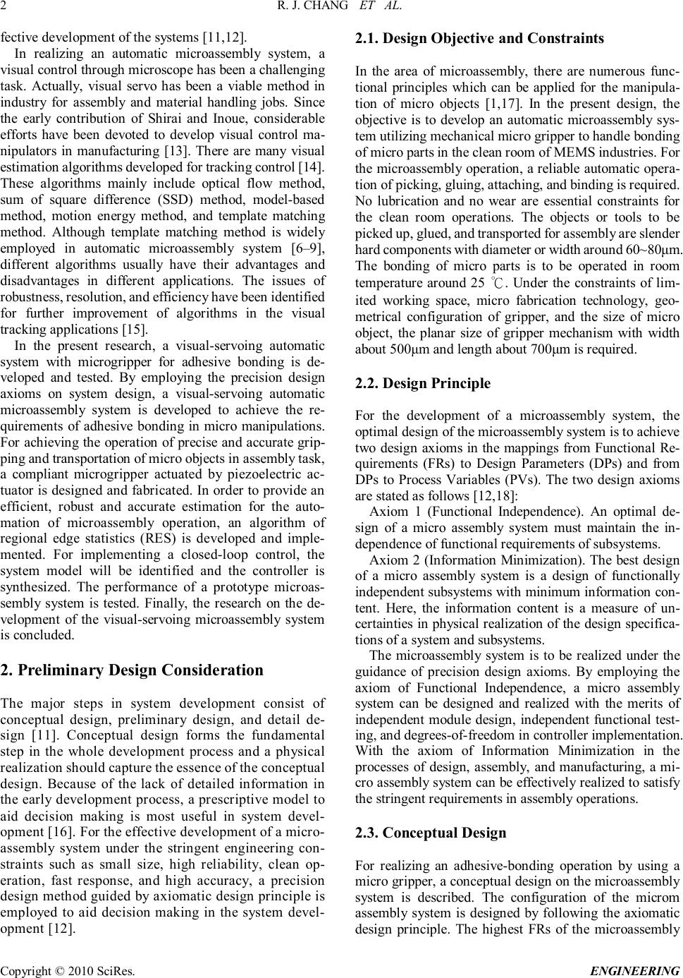 R. J. CHANG ET AL. Copyright © 2010 SciRes. ENGINEERING 2 fective development of the systems [11,12]. In realizing an automatic microassembly system, a visual control through microscope has been a challenging task. Actually, visual servo has been a viable method in industry for assembly and material handling jobs. Since the early contribution of Shirai and Inoue, considerable efforts have been devoted to develop visual control ma- nipulators in manufacturing [13]. There are many visual estimation algorithms developed for tracking control [14]. These algorithms mainly include optical flow method, sum of square difference (SSD) method, model-based method, motion energy method, and template matching method. Although template matching method is widely employed in automatic microassembly system [6–9], different algorithms usually have their advantages and disadvantages in different applications. The issues of robustness, resolution, and efficiency have been identified for further improvement of algorithms in the visual tracking applications [15]. In the present research, a visual-servoing automatic system with microgripper for adhesive bonding is de- veloped and tested. By employing the precision design axioms on system design, a visual-servoing automatic microassembly system is developed to achieve the re- quirements of adhesive bonding in micro manipulations. For achieving the operation of precise and accurate grip- ping and transportation of micro objects in assembly task, a compliant microgripper actuated by piezoelectric ac- tuator is designed and fabricated. In order to provide an efficient, robust and accurate estimation for the auto- mation of microassembly operation, an algorithm of regional edge statistics (RES) is developed and imple- mented. For implementing a closed-loop control, the system model will be identified and the controller is synthesized. The performance of a prototype microas- sembly system is tested. Finally, the research on the de- velopment of the visual-servoing microassembly system is concluded. 2. Preliminary Design Consideration The major steps in system development consist of conceptual design, preliminary design, and detail de- sign [11]. Conceptual design forms the fundamental step in the whole development process and a physical realization should capture the essence of the conceptual design. Because of the lack of detailed information in the early development process, a prescriptive model to aid decision making is most useful in system devel- opment [16]. For the effective development of a micro- assembly system under the stringent engineering con- straints such as small size, high reliability, clean op- eration, fast response, and high accuracy, a precision design method guided by axiomatic design principle is employed to aid decision making in the system devel- opment [12]. 2.1. Design Objective and Constraints In the area of microassembly, there are numerous func- tional principles which can be applied for the manipula- tion of micro objects [1,17]. In the present design, the objective is to develop an automatic microassembly sys- tem utilizing mechanical micro gripper to handle bonding of micro parts in the clean room of MEMS industries. For the microassembly operation, a reliable automatic opera- tion of picking, gluing, attaching, and binding is required. No lubrication and no wear are essential constraints for the clean room operations. The objects or tools to be picked up, glued, and transported for assembly are slender hard components with diameter or width around 60~80μm. The bonding of micro parts is to be operated in room temperature around 25 ℃. Under the constraints of lim- ited working space, micro fabrication technology, geo- metrical configuration of gripper, and the size of micro object, the planar size of gripper mechanism with width about 500μm and length about 700μm is required. 2.2. Design Principle For the development of a microassembly system, the optimal design of the microassembly system is to achieve two design axioms in the mappings from Functional Re- quirements (FRs) to Design Parameters (DPs) and from DPs to Process Variables (PVs). The two design axioms are stated as follows [12,18]: Axiom 1 (Functional Independence). An optimal de- sign of a micro assembly system must maintain the in- dependence of functional requirements of subsystems. Axiom 2 (Information Minimization). The best design of a micro assembly system is a design of functionally independent subsystems with minimum information con- tent. Here, the information content is a measure of un- certainties in physical realization of the design specifica- tions of a system and subsystems. The microassembly system is to be realized under the guidance of precision design axioms. By employing the axiom of Functional Independence, a micro assembly system can be designed and realized with the merits of independent module design, independent functional test- ing, and degrees-of-freedom in controller implementation. With the axiom of Information Minimization in the processes of design, assembly, and manufacturing, a mi- cro assembly system can be effectively realized to satisfy the stringent requirements in assembly operations. 2.3. Conceptual Design For realizing an adhesive-bonding operation by using a micro gripper, a conceptual design on the microassembly system is described. The configuration of the microm assembly system is designed by following the axiomatic design principle. The highest FRs of the microassembly 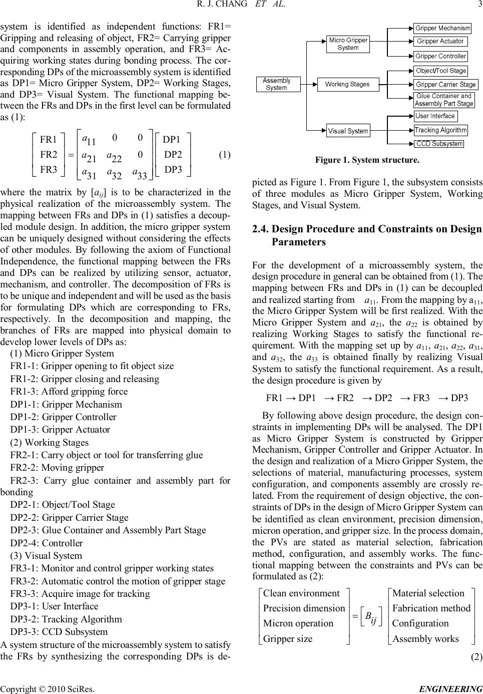 R. J. CHANG ET AL. Copyright © 2010 SciRes. ENGINEERING 3 system is identified as independent functions: FR1= Gripping and releasing of object, FR2= Carrying gripper and components in assembly operation, and FR3= Ac- quiring working states during bonding process. The cor- responding DPs of the microassembly system is identified as DP1= Micro Gripper System, DP2= Working Stages, and DP3= Visual System. The functional mapping be- tween the FRs and DPs in the first level can be formulated as (1): 00 FR1 DP1 11 FR20DP2 2122 FR3DP3 313233 a aa aaa = (1) where the matrix by [a ij] is to be characterized in the physical realization of the microassembly system. The mapping between FRs and DPs in (1) satisfies a decoup- led module design. In addition, the micro gripper system can be uniquely designed without considering the effects of other modules. By following the axiom of Functional Independence, the functional mapping between the FRs and DPs can be realized by utilizing sensor, actuator, mechanism, and controller. The decomposition of FRs is to be unique and independent and will be used as the basis for formulating DPs which are corresponding to FRs, respectively. In the decomposition and mapping, the branches of FRs are mapped into physical domain to develop lower levels of DPs as: (1) Micro Gripper System FR1-1: Gripper opening to fit object size FR1-2: Gripper closing and releasing FR1-3: Afford gripping force DP1-1: Gripper Mechanism DP1-2: Gripper Controller DP1-3: Gripper Actuator (2) Working Stages FR2-1: Carry object or tool for transferring glue FR2-2: Moving gripper FR2-3: Carry glue container and assembly part for bonding DP2-1: Object/Tool Stage DP2-2: Gripper Carrier Stage DP2-3: Glue Container and Assembly Part Stage DP2-4: Controller (3) Visual System FR3-1: Monitor and control gripper working states FR3-2: Automatic control the motion of gripper stage FR3-3: Acquire image for tracking DP3-1: User Interface DP3-2: Tracking Algorithm DP3-3: CCD Subsystem A system structure of the microassembly system to satisfy the FRs by synthesizing the corresponding DPs is de- Figure 1. System structure. picted as Figure 1. From Figure 1, the subsystem consists of three modules as Micro Gripper System, Working Stages, and Visual System. 2.4. Design Procedure and Constraints on Design Parameters For the development of a microassembly system, the design procedure in general can be obtained from (1). The mapping between FRs and DPs in (1) can be decoupled and realized starting from a11. From the mapping by a11, the Micro Gripper System will be first realized. With the Micro Gripper System and a21, the a22 is obtained by realizing Working Stages to satisfy the functional re- quirement. With the mapping set up by a11, a21 , a22 , a31, and a32, the a 33 is obtained finally by realizing Visual System to satisfy the functional requirement. As a result, the design procedure is given by FR1 → DP1 → FR2 → DP2 → FR3 → DP3 By following above design procedure, the design con- straints in implementing DPs will be analysed. The DP1 as Micro Gripper System is constructed by Gripper Mechanism, Gripper Controller and Gripper Actuator. In the design and realization of a Micro Gripper System, the selections of material, manufacturing processes, system configuration, and components assembly are crossly re- lated. From the requirement of design objective, the con- straints of DPs in the design of Micro Gripper System can be identified as clean environment, precision dimension, micron operation, and gripper size. In the process domain, the PVs are stated as material selection, fabrication method, configuration, and assembly works. The func- tional mapping between the constraints and PVs can be formulated as (2): Clean environmentMaterial selection Precision dimensionFabrication method Micron operationConfiguration Gripper sizeAssembly works Bij = (2) 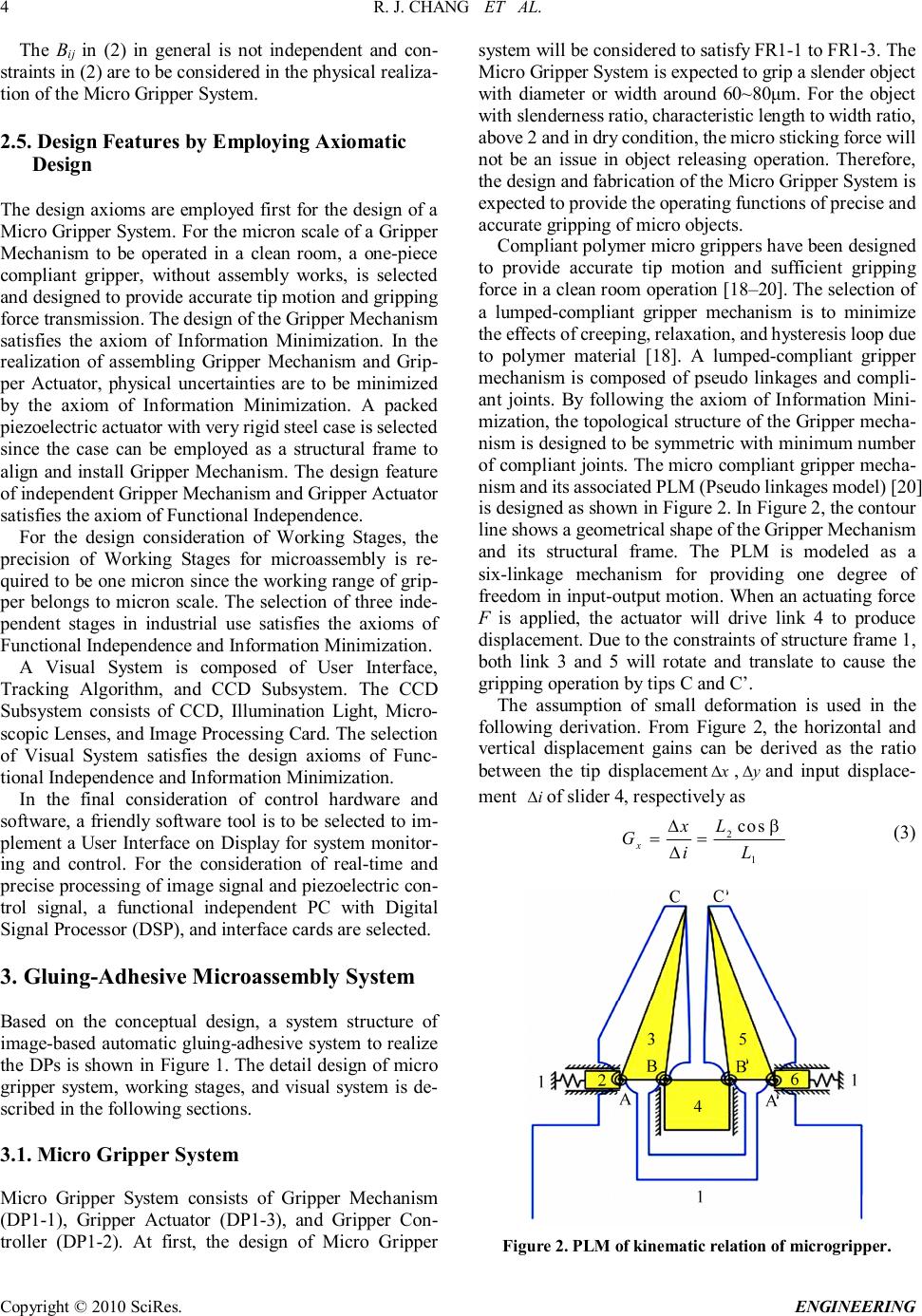 R. J. CHANG ET AL. Copyright © 2010 SciRes. ENGINEERING 4 The Bij in (2) in general is not independent and con- straints in (2) are to be considered in the physical realiza- tion of the Micro Gripper System. 2.5. Design Features by Employing Axiomatic Design The design axioms are employed first for the design of a Micro Gripper System. For the micron scale of a Gripper Mechanism to be operated in a clean room, a one-piece compliant gripper, without assembly works, is selected and designed to provide accurate tip motion and gripping force transmission. The design of the Gripper Mechanism satisfies the axiom of Information Minimization. In the realization of assembling Gripper Mechanism and Grip- per Actuator, physical uncertainties are to be minimized by the axiom of Information Minimization. A packed piezoelectric actuator with very rigid steel case is selected since the case can be employed as a structural frame to align and install Gripper Mechanism. The design feature of independent Gripper Mechanism and Gripper Actuator satisfies the axiom of Functional Independence. For the design consideration of Working Stages, the precision of Working Stages for microassembly is re- quired to be one micron since the working range of grip- per belongs to micron scale. The selection of three inde- pendent stages in industrial use satisfies the axioms of Functional Independence and Information Minimization. A Visual System is composed of User Interface, Tracking Algorithm, and CCD Subsystem. The CCD Subsystem consists of CCD, Illumination Light, Micro- scopic Lenses, and Image Processing Card. The selection of Visual System satisfies the design axioms of Func- tional Independence and Information Minimization. In the final consideration of control hardware and software, a friendly software tool is to be selected to im- plement a User Interface on Display for system monitor- ing and control. For the consideration of real-time and precise processing of image signal and piezoelectric con- trol signal, a functional independent PC with Digital Signal Processor (DSP), and interface cards are selected. 3. Gluing-Adhesive Microassembly System Based on the conceptual design, a system structure of image-based automatic gluing-adhesive system to realize the DPs is shown in Figure 1. The detail design of micro gripper system, working stages, and visual system is de- scribed in the following sections. 3.1. Micro Gripper System Micro Gripper System consists of Gripper Mechanism (DP1-1), Gripper Actuator (DP1-3), and Gripper Con- troller (DP1-2). At first, the design of Micro Gripper system will be considered to satisfy FR1-1 to FR1-3. The Micro Gripper System is expected to grip a slender object with diameter or width around 60~80μm. For the object with slenderness ratio, characteristic length to width ratio, above 2 and in dry condition, the micro sticking force will not be an issue in object releasing operation. Therefore, the design and fabrication of the Micro Gripper System is expected to provide the operating functions of precise and accurate gripping of micro objects. Compliant polymer micro grippers have been designed to provide accurate tip motion and sufficient gripping force in a clean room operation [18–20]. The selection of a lumped-compliant gripper mechanism is to minimize the effects of creeping, relaxation, and hysteresis loop due to polymer material [18]. A lumped-compliant gripper mechanism is composed of pseudo linkages and compli- ant joints. By following the axiom of Information Mini- mization, the topological structure of the Gripper mecha- nism is designed to be symmetric with minimum number of compliant joints. The micro compliant gripper mecha- nism and its associated PLM (Pseudo linkages model) [20] is designed as shown in Figure 2. In Figure 2, the contour line shows a geometrical shape of the Gripper Mechanism and its structural frame. The PLM is modeled as a six-linkage mechanism for providing one degree of freedom in input-output motion. When an actuating force F is applied, the actuator will drive link 4 to produce displacement. Due to the constraints of structure frame 1, both link 3 and 5 will rotate and translate to cause the gripping operation by tips C and C’. The assumption of small deformation is used in the following derivation. From Figure 2, the horizontal and vertical displacement gains can be derived as the ratio between the tip displacement x ∆ , y ∆ and input displace- ment i ∆ of slider 4, respectively as 2 1 cos ∆ == ∆ x Lx GiL β (3) Figure 2. PLM of kinematic relation of microgripper. 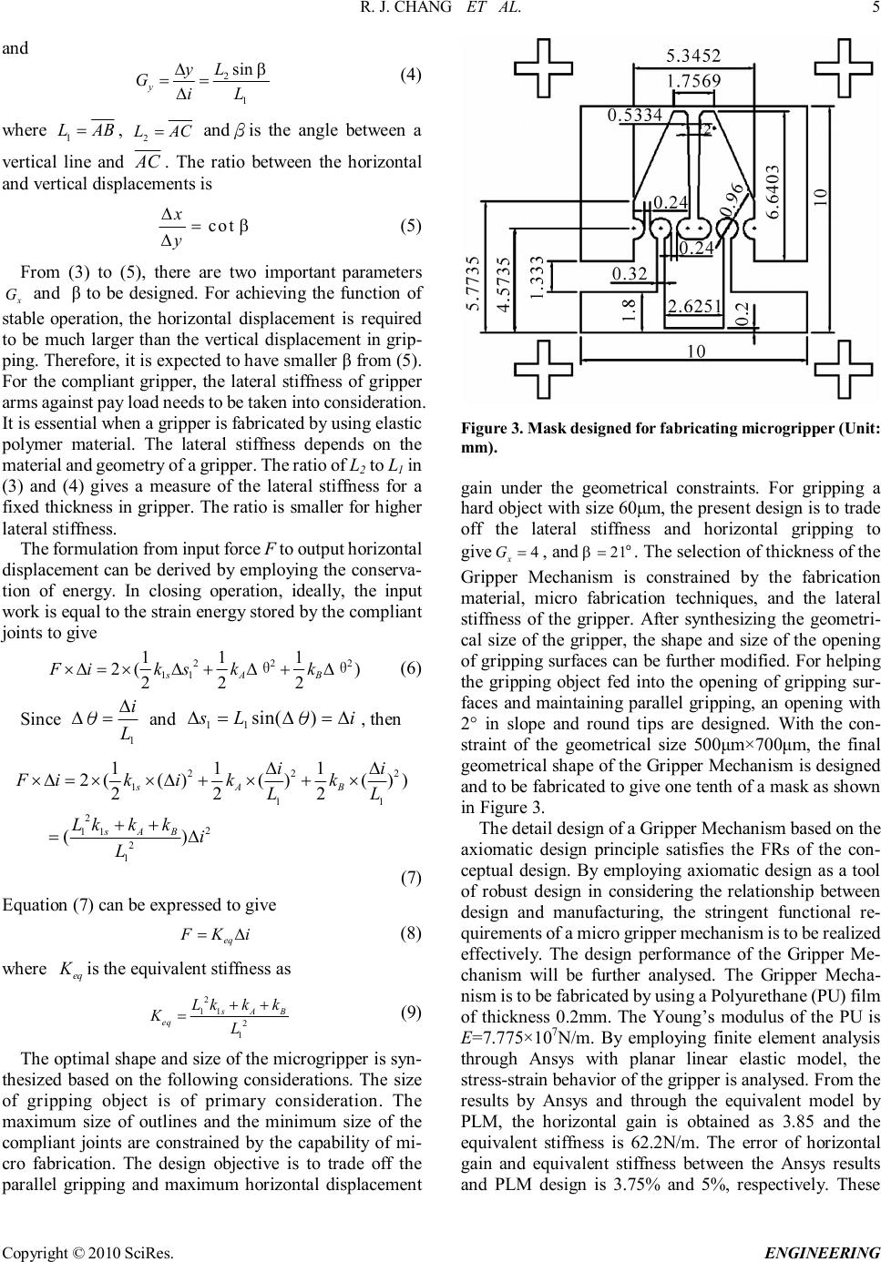 R. J. CHANG ET AL. Copyright © 2010 SciRes. ENGINEERING 5 and 2 1 sin ∆ == ∆ y Ly GiL β (4) where 1 LAB =, 2 LAC = andβis the angle between a vertical line and AC . The ratio between the horizontal and vertical displacements is cot x y β ∆= ∆ (5) From (3) to (5), there are two important parameters x G and β to be designed. For achieving the function of stable operation, the horizontal displacement is required to be much larger than the vertical displacement in grip- ping. Therefore, it is expected to have smaller β from (5). For the compliant gripper, the lateral stiffness of gripper arms against pay load needs to be taken into consideration. It is essential when a gripper is fabricated by using elastic polymer material. The lateral stiffness depends on the material and geometry of a gripper. The ratio of L 2 to L1 in (3) and (4) gives a measure of the lateral stiffness for a fixed thickness in gripper. The ratio is smaller for higher lateral stiffness. The formulation from input force F to output horizontal displacement can be derived by employing the conserva- tion of energy. In closing operation, ideally, the input work is equal to the strain energy stored by the compliant joints to give 222 11 111 2() 222 sAB Fikskk×∆=×∆+∆+∆θ θ (6) Since 1 ∆ ∆=θ i L and 11 sin() sLi ∆=∆=∆ θ, then 222 1 11 22 11 2 1 111 2(()()()) 222 () sAB sAB ii Fikikk LL Lkkk i L ∆∆ ×∆=××∆+×+× ++ =∆ (7) Equation (7) can be expressed to give eq FKi =∆ (8) where eq K is the equivalent stiffness as 2 11 2 1 ++ = sAB eq Lkkk KL (9) The optimal shape and size of the microgripper is syn- thesized based on the following considerations. The size of gripping object is of primary consideration. The maximum size of outlines and the minimum size of the compliant joints are constrained by the capability of mi- cro fabrication. The design objective is to trade off the parallel gripping and maximum horizontal displacement Figure 3. Mask designed for fabricating microgripper (Unit: mm). gain under the geometrical constraints. For gripping a hard object with size 60μm, the present design is to trade off the lateral stiffness and horizontal gripping to give 4 x G = , and 21 β= o . The selection of thickness of the Gripper Mechanism is constrained by the fabrication material, micro fabrication techniques, and the lateral stiffness of the gripper. After synthesizing the geometri- cal size of the gripper, the shape and size of the opening of gripping surfaces can be further modified. For helping the gripping object fed into the opening of gripping sur- faces and maintaining parallel gripping, an opening with 2° in slope and round tips are designed. With the con- straint of the geometrical size 500μm×700μm, the final geometrical shape of the Gripper Mechanism is designed and to be fabricated to give one tenth of a mask as shown in Figure 3. The detail design of a Gripper Mechanism based on the axiomatic design principle satisfies the FRs of the con- ceptual design. By employing axiomatic design as a tool of robust design in considering the relationship between design and manufacturing, the stringent functional re- quirements of a micro gripper mechanism is to be realized effectively. The design performance of the Gripper Me- chanism will be further analysed. The Gripper Mecha- nism is to be fabricated by using a Polyurethane (PU) film of thickness 0.2mm. The Young’s modulus of the PU is E=7.775×10⁷N/m. By employing finite element analysis through Ansys with planar linear elastic model, the stress-strain behavior of the gripper is analysed. From the results by Ansys and through the equivalent model by PLM, the horizontal gain is obtained as 3.85 and the equivalent stiffness is 62.2N/m. The error of horizontal gain and equivalent stiffness between the Ansys results and PLM design is 3.75% and 5%, respectively. These  R. J. CHANG ET AL. Copyright © 2010 SciRes. ENGINEERING 6 results support the validity of utilizing PLM in design. The fabrication of the micro Gripper System is con- sidered by following the axiom of Information Minimi- zation. The PU micro Gripper Mechanism is fabricated by employing a mask projection method instead of a direct write method. By employing an excimer laser, Exitech 2000, the fabricated micro Gripper Mechanism through mask is reduced by the optical lens of 10x. The fabricated Gripper Mechanism with Gripper Actuator is assembled through a metal coupler by utilizing simple hand tools and with adhesive glue. The Gripper Actuator with Gripper Controller can provide 10μm linear displacement. With much higher stiffness of Gripper Actuator to drive the lower stiffness of Gripper Mechanism, the gripper as- sembly can provide sufficient gripping force in the grip- ping range 60μm to 80μm by input 0 to 80 volts from the Gripper Controller. 3.2. Working Stages Working Stages include Object/Tool Stage (DP2-1), Gripper Carrier Stage (DP2-2), and Glue Container and Assembly Part Stage (DP2-3). By following the guidance of design axioms, these stages are implemented by se- lecting industrial products to satisfy FR2-1 to FR2-3. Two three-axes stages for Object/Tool Stage and Glue Con- tainer and Assembly Part Stage are obtained from New- port. The three-axes stages are driven by stepping motors and can provide 1.3μm resolution with 15mm stroke. Gripper Carrier Stage obtained from Physik Instrumente is implemented to give 0.5μm resolution with 15mm stroke for planar X-Y motion. 3.3. Visual System Visual System consists of User Interface (DP3-1), Tracking Algorithm (DP3-2), and CCD Subsystem (DP3-3). By following the guidance of Information Minimization in implementing an image acquisition sys- tem for visual servo, the installation of Visual System is to adopt Endpoint Closed Loop (ECL) scheme and the structure of visual servo is to adopt the Dynamic Im- age-Based Look-and-Move (DIBLM) scheme. For image acquisition to satisfy FR3-3, hardware is set up to include JAI CVS3200 CCD with lens, TI vDB im- age grabber card, and TI DSP320C6711 DSK board. The imaging model adopts affine projection. In this case, a point with coordinates as c P , expressed with respect to the Cartesian coordinate frame of a camera, will project onto an image plane as [ ] y T x by c x y =+ APc (10) where A and c are calibrated 2x3 and 2x1 matrix, respec- tively. The model is purely linear. The A and c are easily computed by using linear regression techniques. Since affine projection does not correspond to any specific imaging situation, the issue of camera calibration is greatly simplified. The affine projection can be simpli- fied to a scaled orthographic projection if A is reduced to a scalar and c is zero. The DIBLM scheme provides several advantages. First, the system with DIBLM structure doesn ’t need coordinate transformation and consequently, the control performance is independent of the calibration. Second, it is more effi- cient in computation. Thus, the computational load on control structure is not stringent in implementation. Third, it is suitable for the present realization of a planar vis- ual-servoing microassembly operation. The design axioms provide an efficient and effective tool to help logical reasoning and decision making in obtaining an optimal design of the microassembly system. The system framework of hardware installation is shown in Figure 4. The image-based automatic operation of gluing-adhesive bonding is to implement control software on a PC and through a motion control card, NI-3744 and communication interface, RS-232. LabView is selected to implement control windows for DP3-1. The selection of LabView for implementing control windows to satisfy FR3-1 is based on the guidance of Minimum Information. For the microassembly system, all the assembly works are operated under the field of view of a visual system by DP3-1 to DP3-3. The detail designs of DP3-1 and DP3-3 were described in this section. A tracking algorithm to realize DP3-2 will be developed in next section. 4. Tracking Algorithm The performance of an algorithm which tracks an object from the features of its image plays a key role to imple- ment a visual-servoing system. In general, edges are most essential features of an object employed in image tracking. If the shape of an object has clear edge features in the image, the geometric features such as length, width, area, and centroid, depending on the representative of these edge features, can be fully or partially determined to construct a feature space of the object. An object with symmetrical geometry in image is a typical object that the edge is representative of its centroid. For estimating the geometric centroid of an object from the edge features of the image, it is required that the image is under conditions: 1) The edge of an object is representative of its cen- troid. 2) There is no high frequency spatial noise in back- ground. By employing the concepts of interesting region and edge feature, a dynamic image tracking algorithm, Re- gional Edge Statistics (RES), is developed. In the initial time instant k, the initial center of a tracking region was defined as the centroid of the micro gripper and repre- 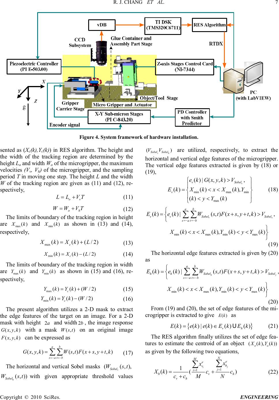 R. J. CHANG ET AL. Copyright © 2010 SciRes. ENGINEERING 7 Figure 4. System framework of hardware installation. sented as (Xc(k),Yc(k)) in RES algorithm. The height and the width of the tracking region are determined by the height Lo and width Wo of the microgripper, the maximum velocities (Vv, Vh) of the microgripper, and the sampling period T in moving one step. The height L and the width W of the tracking region are given as (11) and (12), re- spectively, ov LLVT =+ (11) oh WWVT =+ (12) The limits of boundary of the tracking region in height are max () Xk and min () Xk as shown in (13) and (14), respectively, max ()()(/2) c XkXkL=+ (13) min ()()(/2) c XkXkL=− (14) The limits of boundary of the tracking region in width are max () Yk and min () Yk as shown in (15) and (16), re- spectively, max ()()(/2) c YkYkW=+ (15) min ()()(/2) c YkYkW=− (16) The present algorithm utilizes a 2-D mask to extract the edge features of the target on an image. For a 2-D mask with height 2 a and width 2 b , the image response (,,) Gxyk with a mask (,) Wst on an original image (,,) Fxyk can be expressed as (,,)(,)(,,) ab satb GxykWstFxsytk =−=− =++ ∑∑ (17) The horizontal and vertical Sobel masks ((,), v Sobel Wst (,)) h Sobel Wst with given appropriate threshold values () vh SobelSobel VV are utilized, respectively, to extract the horizontal and vertical edge features of the microgripper. The vertical edge features extracted is given by (18) or (19), minmaxmin max ()|(,,), ()()(), ()() v vSobel v ekGxykV EkXkxXkY kyYk > =<< << (18) minmaxminmax ()()|(,)(,,), ()(),()() vx ab vvSobelSobel satb EkekWstFxsytkV XkxXkYkyYk =−=− =++> <<<< ∑∑ (19) The horizontal edge features extracted is given by (20) as minmaxminmax ()()|(,)(,,), ()(),()() hy ab hhSobelSobel satb EkekWstFxsytkV XkxXkYkyYk =−=− =++> <<<< ∑∑ (20) From (19) and (20), the set of edge features of the mi- crogripper is extracted to give () Ek as { } ()()|()()() vh EkekekEkEk =∈ U (21) The RES algorithm finally utilizes the set of edge fea- tures to estimate the centroid of an object ((),()) oo XkYk as given by the following two equations, 1 1 01 ()() j i N Me eh vj ivh vh x x Xkcc ccMN = = =+ + ∑ ∑ (22) 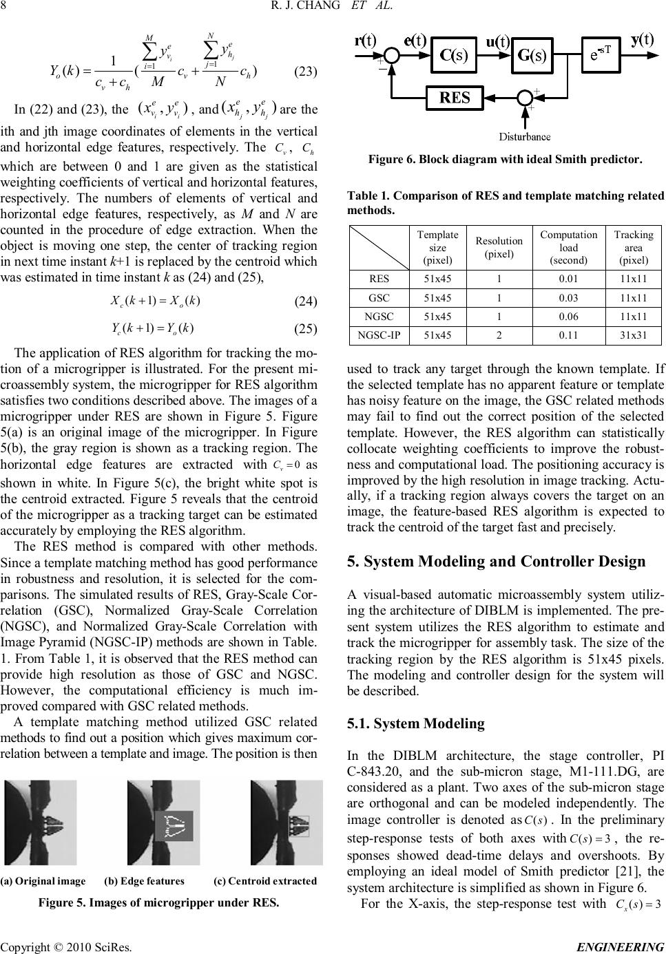 R. J. CHANG ET AL. Copyright © 2010 SciRes. ENGINEERING 8 1 1 1 ()() j i N Me eh vj i ovh vh y y Ykcc ccMN = = =+ + ∑ ∑ (23) In (22) and (23), the (,) ii ee vv xy , and (,) jj ee hh xy are the ith and jth image coordinates of elements in the vertical and horizontal edge features, respectively. The v C , h C which are between 0 and 1 are given as the statistical weighting coefficients of vertical and horizontal features, respectively. The numbers of elements of vertical and horizontal edge features, respectively, as M and N are counted in the procedure of edge extraction. When the object is moving one step, the center of tracking region in next time instant k+1 is replaced by the centroid which was estimated in time instant k as (24) and (25), (1)() += co XkXk (24) (1)() += co YkYk (25) The application of RES algorithm for tracking the mo- tion of a microgripper is illustrated. For the present mi- croassembly system, the microgripper for RES algorithm satisfies two conditions described above. The images of a microgripper under RES are shown in Figure 5. Figure 5(a) is an original image of the microgripper. In Figure 5(b), the gray region is shown as a tracking region. The horizontal edge features are extracted with 0 v C = as shown in white. In Figure 5(c), the bright white spot is the centroid extracted. Figure 5 reveals that the centroid of the microgripper as a tracking target can be estimated accurately by employing the RES algorithm. The RES method is compared with other methods. Since a template matching method has good performance in robustness and resolution, it is selected for the com- parisons. The simulated results of RES, Gray-Scale Cor- relation (GSC), Normalized Gray-Scale Correlation (NGSC), and Normalized Gray-Scale Correlation with Image Pyramid (NGSC-IP) methods are shown in Table. 1. From Table 1, it is observed that the RES method can provide high resolution as those of GSC and NGSC. However, the computational efficiency is much im- proved compared with GSC related methods. A template matching method utilized GSC related methods to find out a position which gives maximum cor- relation between a template and image. The position is then (a) Original image (b) Edge features (c) Centroid extracted Figure 5. Images of microgripper under RES. Figure 6. Block diagram with ideal Smith predictor. Table 1. Comparison of RES and template matching related methods. Template size (pixel) Resolution (pixel) Computation load (second) Tracking area (pixel) RES 51x45 1 0.01 11x11 GSC 51x45 1 0.03 11x11 NGSC 51x45 1 0.06 11x11 NGSC-IP 51x45 2 0.11 31x31 used to track any target through the known template. If the selected template has no apparent feature or template has noisy feature on the image, the GSC related methods may fail to find out the correct position of the selected template. However, the RES algorithm can statistically collocate weighting coefficients to improve the robust- ness and computational load. The positioning accuracy is improved by the high resolution in image tracking. Actu- ally, if a tracking region always covers the target on an image, the feature-based RES algorithm is expected to track the centroid of the target fast and precisely. 5. System Modeling and Controller Design A visual-based automatic microassembly system utiliz- ing the architecture of DIBLM is implemented. The pre- sent system utilizes the RES algorithm to estimate and track the microgripper for assembly task. The size of the tracking region by the RES algorithm is 51x45 pixels. The modeling and controller design for the system will be described. 5.1. System Modeling In the DIBLM architecture, the stage controller, PI C-843.20, and the sub-micron stage, M1-111.DG, are considered as a plant. Two axes of the sub-micron stage are orthogonal and can be modeled independently. The image controller is denoted as () Cs . In the preliminary step-response tests of both axes with ()3 Cs = , the re- sponses showed dead-time delays and overshoots. By employing an ideal model of Smith predictor [21], the system architecture is simplified as shown in Figure 6. For the X-axis, the step-response test with ()3 x Cs = 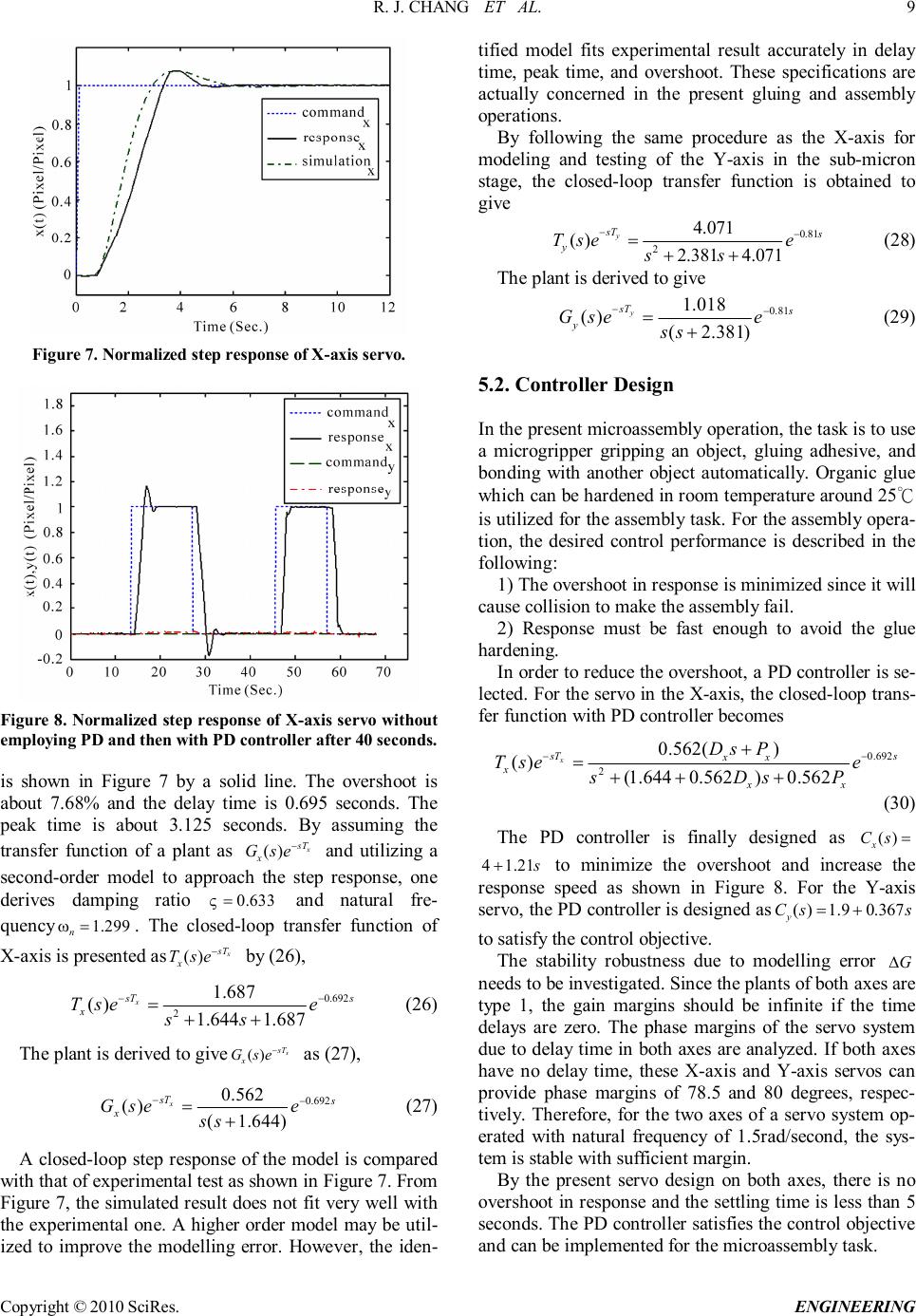 R. J. CHANG ET AL. Copyright © 2010 SciRes. ENGINEERING 9 Figure 7. Normalized step response of X-axis servo. Figure 8. Normalized step response of X-axis servo without employing PD and then with PD controller after 40 seconds. is shown in Figure 7 by a solid line. The overshoot is about 7.68% and the delay time is 0.695 seconds. The peak time is about 3.125 seconds. By assuming the transfer function of a plant as () x sT x Gse − and utilizing a second-order model to approach the step response, one derives damping ratio 0.633 ς = and natural fre- quency 1.299 n ω = . The closed-loop transfer function of X-axis is presented as () x sT x Tse − by (26), 0.692 2 1.687 () 1.6441.687 x sT s x Tsee ss − − = ++ (26) The plant is derived to give () x sT x Gse − as (27), 0.692 0.562 () (1.644) x sT s x Gsee ss −− =+ (27) A closed-loop step response of the model is compared with that of experimental test as shown in Figure 7. From Figure 7, the simulated result does not fit very well with the experimental one. A higher order model may be util- ized to improve the modelling error. However, the iden- tified model fits experimental result accurately in delay time, peak time, and overshoot. These specifications are actually concerned in the present gluing and assembly operations. By following the same procedure as the X-axis for modeling and testing of the Y-axis in the sub-micron stage, the closed-loop transfer function is obtained to give 0.81 2 4.071 () 2.3814.071 y sT s y Tsee ss −− = ++ (28) The plant is derived to give 0.81 1.018 () (2.381) y sT s y Gsee ss −− =+ (29) 5.2. Controller Design In the present microassembly operation, the task is to use a microgripper gripping an object, gluing adhesive, and bonding with another object automatically. Organic glue which can be hardened in room temperature around 25℃ is utilized for the assembly task. For the assembly opera- tion, the desired control performance is described in the following: 1) The overshoot in response is minimized since it will cause collision to make the assembly fail. 2) Response must be fast enough to avoid the glue hardening. In order to reduce the overshoot, a PD controller is se- lected. For the servo in the X-axis, the closed-loop trans- fer function with PD controller becomes 0.692 2 0.562() () (1.6440.562)0.562 x sT s xx x xx DsP Tsee sDsP − − + = +++ (30) The PD controller is finally designed as () x Cs = 41.21 s + to minimize the overshoot and increase the response speed as shown in Figure 8. For the Y-axis servo, the PD controller is designed as ()1.90.367 y Css =+ to satisfy the control objective. The stability robustness due to modelling error G ∆ needs to be investigated. Since the plants of both axes are type 1, the gain margins should be infinite if the time delays are zero. The phase margins of the servo system due to delay time in both axes are analyzed. If both axes have no delay time, these X-axis and Y-axis servos can provide phase margins of 78.5 and 80 degrees, respec- tively. Therefore, for the two axes of a servo system op- erated with natural frequency of 1.5rad/second, the sys- tem is stable with sufficient margin. By the present servo design on both axes, there is no overshoot in response and the settling time is less than 5 seconds. The PD controller satisfies the control objective and can be implemented for the microassembly task. 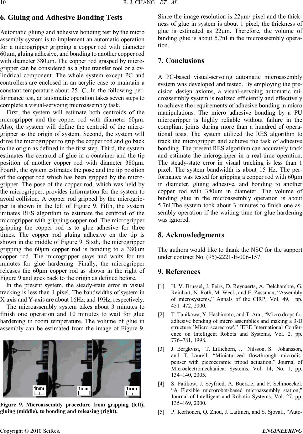 R. J. CHANG ET AL. Copyright © 2010 SciRes. ENGINEERING 10 6. Gluing and Adhesive Bonding Tests Automatic gluing and adhesive bonding test by the micro assembly system is to implement an automatic operation for a microgripper gripping a copper rod with diameter 60μm, gluing adhesive, and bonding to another copper rod with diameter 380 μm. The copper rod grasped by micro- gripper can be considered as a glue transfer tool or a cy- lindrical component. The whole system except PC and controllers are enclosed in an acrylic case to maintain a constant temperature about 25 ℃. In the following per- formance test, an automatic operation takes seven steps to complete a visual-servoing microassembly task. First, the system will estimate both centroids of the microgripper and the copper rod with diameter 60μm. Also, the system will define the centroid of the micro- gripper as the origin of system. Second, the system will drive the microgripper to grip the copper rod and go back to the origin as defined in the first step. Third, the system estimates the centroid of glue in a container and the tip position of another copper rod with diameter 380 μm. Fourth, the system estimates the pose and the tip position of the copper rod which has been gripped by the micro- gripper. The pose of the copper rod, which was held by the microgripper, provides information for the system to avoid collision. A copper rod gripped by the microgrip- per is shown in the left of Figure 9. Fifth, the system initiates RES algorithm to estimate the centroid of the microgripper with gripping copper rod. The microgripper gripping the copper rod is to glue adhesive for three times. The copper rod gluing adhesive on the tip is shown in the middle of Figure 9. Sixth, the microgripper gripping the 60μm copper rod is bonding to a 380μm copper rod. The microgripper stays and waits for ten minutes for glue hardening. Finally, the microgripper releases the 60μm copper rod as shown in the right of Figure 9 and goes back to the origin as defined before. In the present system, the steady-state error in visual tracking is less than 1 pixel. The bandwidths of system in X-axis and Y-axis are about 16Hz, and 19Hz, respectively. The microassembly system takes about 3 minutes to finish one operation and 10 minutes to wait for glue hardening in room temperature. The volume of glue in assembly can be estimated from the image of Figure 9. Figure 9. Microassembly procedure from gripping (left), gluing (middle), to bonding and releasing (right). Since the image resolution is 22μm/ pixel and the thick- ness of glue in system is about 1 pixel, the thickness of glue is estimated as 22μm. Therefore, the volume of binding glue is about 5.7nl in the microassembly opera- tion. 7. Conclusions A PC-based visual-servoing automatic microassembly system was developed and tested. By employing the pre- cision design axioms, a visual-servoing automatic mi- croassembly system is realized efficiently and effectively to achieve the requirements of adhesive bonding in micro manipulations. The micro adhesive bonding by a PU microgripper is highly reliable without failure in the compliant joints during more than a hundred of opera- tional tests. The system utilized the RES algorithm to track the microgripper and achieve the task of adhesive bonding. The present RES algorithm can accurately track and estimate the microgripper in a real-time operation. The steady-state error in visual tracking is less than 1 pixel. The system bandwidth is about 15 Hz. The per- formance was tested for gripping a copper rod with 60μm in diameter, gluing adhesive, and bonding to another copper rod with 380μm in diameter. The volume of binding glue in the microassembly operation is about 5.7nl.The system took about 3 minutes to finish one as- sembly operation if the waiting time for glue hardening was ignored. 8. Acknowledgments The authors would like to thank the NSC for the support under contract No. (95)-2221-E-006-157. 9. References [1] H. V. Brussel, J. Peirs, D. Reynaerts, A. Delchambre, G. Reinhart, N. Roth, M. Weck, and E. Zussman, “Assembly of microsystems,” Annals of the CIRP, Vol. 49, pp. 451–472, 2000. [2] T. Tanikawa, Y. Hashimoto, and T. Arai, “Micro drops for adhesive bonding of micro assemblies and making a 3-D structure `Micro scarecrow',” IEEE International Confer- ence on Intelligent Robots and Systems, Vol. 2, pp. 776–781, 1998. [3] J. Bergkvist, T. Lilliehorn, J. Nilsson, S. Johansson, and T. Laurell, “Miniaturized flowthrough microdis- penser with piezoceramic tripod actuation,” Journal of Microelectromechanical Systems, Vol. 14, No. 1, pp. 134–140, 2005. [4] S. Fatikow, J. Seyfried, A. Buerkle, and F. Schmoeckel, “A Flexible microrobot-based microassembly station,” Journal of Intelligent and Robotic Systems, Vol. 27, pp. 135–169, 2000. [5] P. Korhonen, Q. Zhou, J. Laitinen, and S. Sjovall, “Auto-  R. J. CHANG ET AL. Copyright © 2010 SciRes. ENGINEERING 11 matic dextrous handling of micro components using a 6 DOF microgripper,” Proceedings of 2005 IEEE Interna- tional Symposium on Computational Intelligence in Ro- botics and Automation, pp. 125–131, 2005. [6] A. Ferreira, C. Cassier, and S. Hirai, “Automatic mi- croassembly system assisted by vision servoing and virtual reality,” IEEE/ASME Transactions on Mechatronics, Vol. 9, No. 2, pp. 321–333, 2004. [7] K. B. Yesin and B. J. Nelson, “A CAD model based tracking system for visually guided microassembly,” Robotica, Vol. 23, pp. 409–418, 2005. [8] Y. H. Anis, J. K. Mills, and W. L. Cleghorn, “Automated microassembly task execution using vision-based feed- back control,” IEEE Proceedings of the 2007 International Conference on Information Acquisition, Vol. 9, No. 2, pp. 321–333, 2007. [9] L. Ren, L. Wang, J. K. Mills, and D. Sun, “Vision-based 2-D automatic micrograsping using coarse-to-fine grasp- ing strategy,” IEEE Transactions on Industrial Electronics, Vol. 55, No. 9, pp. 3324–3331, 2008. [10] G. Yang, J. A. Gaines, and B. J. Nelson, “Optomecha- tronic design of microassembly systems for manufacturing hybrid microsystems,” IEEE Transactions on Industrial Electronics, Vol. 52, No. 4, pp. 1013–1023, 2005. [11] B. S. Blanchard, “System Engineering Management,” New York, Wiley, 1991. [12] N. P. Suh, “The Principles of Design,” New York, Oxford University Press, 1990. [13] S. Hutchinson, G. D. Hager, and P. I. Corke, “A tutorial on visual servo control,” IEEE Transactions on Robotics and Automation, Vol. 12, No. 5, pp. 651–670, 1996. [14] E. Trucco and K. Plakas, “Video tracking: a concise sur- vey,” IEEE Journal of Oceanic Engineering, Vol. 31, No. 2, pp. 520–529, 2006. [15] G. Zhu, Q. Zeng, and C. Wang, “Efficient edge-based object tracking,” Pattern Recognition, Vol. 39, pp. 2223 – 2226, 2006. [16] D. Braha and O. Maimon, “The design process: properties, paradigms, and structure, ” IEEE Transactions on Systems, Man, and Cybernetics, Vol. 27, No. 2, pp. 146–166, 1997. [17] S. Fatikow and U. Rembold, “Microsystem technology and microrobotics,” Berlin, Springer, 1997. [18] R. J. Chang, H. S. Wang, and Y. L. Wang, “Development of mesoscopic polymer gripper system guided by preci- sion design axioms,” Precision Engineering, Vol. 27, pp. 362–369, 2003. [19] R. J. Chang, P. W. Shih, R. Z. Huang, and K. L. Lin, “Application of piezo-driven polymer microgripper in automatic transportation of micro object, ” IEEE Interna- tional Conference of Mechatronics, pp. 140–144, 2005. [20] R. J. Chang and Y. L. Wang, “Integration method for input-output modeling and error analysis of four-bar polymer compliant micromachines, ” ASME Journal of Mechanical Design, Vol. 121, pp. 220–228, 1999. [21] O. J. Smith, “A controller to overcome dead time, ” ISA Journal, Vol. 6, pp. 28– 33, 1959. |

