Engineering
Vol. 3 No. 12 (2011) , Article ID: 9216 , 6 pages DOI:10.4236/eng.2011.312153
Challenges in Qualitative Accelerated Testing of WSN Hardware
1Department of Electronics, Tampere University of Technology, Tampere, Finland
2School of Information Science and Engineering, Southeast University, Nanjing, China
E-mail: Johanna.virkki@tut.fi, lqchen@seu.edu.cn
Received October 25, 2011; revised November 12, 2011; accepted November 25, 2011
Keywords: Accelerated Testing, Internet of Things, Reliability, Wireless Sensor Network
ABSTRACT
Internet of Things (IOT) is a conceptual vision to connect things in order to create a ubiquitous computing world. In order to create such an ever-present network, a simple, reliable, and cost-effective technology is crucial. Wireless sensor network (WSN) is an important wireless technology that has wide variety of applications and provides unlimited future potentials for IOT. Since WSNs in IOT will be used in varying and challenging applications and environments, reliability and reliability testing of WSN hardware becomes extremely important. In accelerated reliability testing, test stresses are increased to cut down the time required to obtain a weakening effect similar to one resulting from normal service conditions in the field. This paper introduces three common difficulties that engineers may experience in qualitative accelerated testing of WSN devices: 1) Challenges in use of standard accelerated tests, 2) Challenges in component-level testing, and 3) Challenges in testing of prototypes. The paper will also introduce examples from real life reliability research and accelerated tests to clarify the presented challenges.
1. Introduction
Internet of Things (IOT) is a conceptual vision to connect things (everyday things from buildings to coffee cups) and devices (mobile phones to ovens), in order to create a ubiquitous computing world. In IOT, things have identities, physical attributes, and virtual personalities; they use intelligent interfaces, and are seamlessly integrated into the information network. The information stored on the connected things can be shared, provided, and processed automatically. Things are expected to become active participants in business, information and social processes where they are enabled to interact and communicate among themselves, with humans, and with the environment. Things will exchange data and information about the environment, while reacting autonomously to different events, influencing the environment, and creating services with or without human intervention. IOT is thus the extension of the internet to the next level, i.e., bringing the internet to the real physical world of things. It has a great potential in healthcare, disaster prevention, home automation, and intelligent transportation [1,2].
In order to connect everyday objects to large networks, a simple, reliable, and cost-effective technology is crucial. Wireless sensor network (WSN) is an important wireless technology that has wide variety of applications and provides unlimited future potentials. A WSN can have from a few to several thousand collaborating nodes with computing, data processing, and communicating components. Each node is connected to one or more sensors. The sensors are used to collect and transmit information about their surrounding environment. The node collects the information from a group of sensors and facilitates communication with a control center [3,4].
WSN-based IOT applications will be used in varying and challenging environments and hardware reliability problems can have catastrophic consequences. Some common reasons for failures of hardware are environmental contaminants and conditions such as temperature, temperature changes, and humidity with other failures deriving, e.g., from vibration, ripple voltage, and overvoltage. These all affect the reliability of WSN devices. To achieve reliable and durable WSNs for IOT applications, reliability testing of hardware is needed. Traditional reliability test plans aim to simulate the product’s use environment. Because such testing is expensive and time-consuming, accelerated testing becomes necessary.
2. Accelerated Testing
In accelerated testing, test stresses are increased to cut down the time required to obtain a weakening effect similar to one resulting from normal field conditions. There are many ways to define the stress limits. In our research, we divide them into three: specification limits, design limits, and destruct limits. The specification limits are set by the manufacturer to limit the stresses during field use. The design limits are the limits that the product will survive without failure. The destruct limit is the fundamental limit of technology, where the product falls apart [5]. Normally, stress levels in accelerated tests will fall outside the product specification limits but within the design limits. Stress levels in accelerated tests are shown in Figure 1.
Usually, accelerated testing can be divided into two areas: qualitative and quantitative. The former focuses on identifying failures without attempting any predictions as to the product’s operation under normal use conditions. It is used primarily to reveal probable failure modes for the product so that product engineers can improve the product design. The latter seeks to predict the lifetime of the product in normal use [5-7]. Qualitative accelerated tests should first be used to reveal probable failure modes and mechanisms that WSN devices may have in the field. All stresses that a particular device is subjected to in the field should be considered when testing the reliability. After qualitative testing, quantitative accelerated tests can be designed to produce the data required for estimating lifetime of the product under normal use conditions.
This paper introduces potential challenges that engineers may experience and things they need to take into account in qualitative accelerated testing of WSN-based IOT devices. It is a combination of a literature review and experiments from real life reliability research.
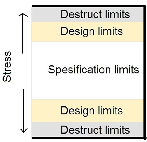
Figure 1. Stress levels in accelerated tests.
3. Challenges in Accelerated Testing
The general objectives of both kinds of accelerated tests are to determine the component’s limits by applying stresses high enough to induce failures, to quickly discover the root causes of failures occurring in field use, and thus improve reliability [8,9]. This paper concentrates on qualitative accelerated testing. Failure analysis is done in order to understand the results of qualitative accelerated testing. Failure analysis of failed components/products is necessary to clarify the cause of failure and to provide rapid feedback to the process stages of design and manufacture. Failure analysis investigates the mode, site, and mechanism of failure using optical, electrical, physical, and chemical techniques. A major worry is that an accelerated test will somehow miss a failure mode that will cause disaster in normal operation. On the other hand, an accelerated test may condemn a wellworking new product by identifying an artificial failure mode as real [6,7,10-12]. In some cases, infant mortality failures might occur concurrently with the operational failures [11]. It is important to make sure that these failures are well separated in the tests. It is also possible that in accelerated testing, while focusing on one known failure mode, one might mask another. However, it can be the masked failure mode that is the first one to show up in the field. In such cases, the masked failure modes often dominate reported field failures. In some cases, it is possible that increasing stress (that is thought to accelerate failures) will actually cause deceleration. For example, an increased temperature may result as lower humidity in the “accelerated” test and the primary failure mode in the field can be caused by corrosion that would not occur at high temperature and low humidity [6,7]. Thus, poor accelerated tests waste time, effort, and money, and may not even yield the desired information.
4. Reliability of WSN-Based IOT Applications
In IOT applications, electronics can be deployed in controlled environments, such as factories, homes, or hospitals. They also can be deployed in uncontrolled and harsh environments, such as in changing weather conditions, seacoast conditions, disaster areas, or battlefields. The environment may also vary between the life-phases of the device from manufacturing to disposal. In addition, electronics generate own internal stresses purely by functioning, heat up and cool down during their use cycles and, by doing so, generate thermo-mechanical stresses. Power saving strategies in IOT applications may accelerate this problem because there may be more frequent wake-sleep cycles. Also, the device is often woken up for data transmission, which generates the greatest amount of heat of which the device is capable of enduring. In addition to thermally induced stresses, there will also be the voltage and current stresses that are inherent to any electronic device [13].
Hardware reliability is only one of the demands for a working WSN. A large WSN, with sufficient node capacity, can afford to lose nodes to hardware failure without the entire system failing through the use of redundancy, re-routing and preventative maintenance, managed at higher levels of the stack. However, the design of a WSN with sufficient node capacity for redundancy, re-routing and preventative maintenance requires information on the hardware reliability at field conditions. This, in turn, requires a detailed hardware reliability analysis [13].
Also, since WSNs are relatively youthful topics with few long-term field deployments, the effects of a lack of hardware reliability may not have yet caused a worryinducing impact. Thus, it may seem that hardware reliability is not among the most important things when designing a WSN. However, in many WSN applications, reliability of hardware is essential and field failures may have catastrophic results. In addition, reliability predicttion of hardware is important, since sensor devices are planned to be unattended for long periods without maintenance. Next, three common challenges in qualitative accelerated testing of WSN devices will be introduced. Examples from real life reliability research will also be presented.
5. Use of Standard Accelerated Tests
It is a common practice to test reliability only with standard tests. Many standard tests are available, and one can be chosen based on field conditions and the tested product. Possible standards are e.g. the Joint Electron Device Engineering Council (JEDEC) standards and the MIL (US Military) standards. Standard tests form a good basis for reliability testing. However, they are not perfect: They can be quite time-consuming and fail to take into account all field conditions. In some cases, results can be achieved much faster, and a shorter test would then suffice. Sometimes, a standard test plainly fails to detect a critical failure mechanism occurring in the field in almost similar conditions as those accelerated in the test [12,14-16]. In addition, for WSN electronics, we must add the complication of spatial variations in environmental stresses depending on the physical location of the node. As it is unlikely, except in cases where the spatial variation in stresses is extreme, that a custom node will be designed for each environment, there is the challenge of having to design and test a node so that it will endure temporally and spatially varying stresses. Since WSNs in IOT will be used in varying and challenging applications and environments, the use of only standard accelerated tests is not an alternative. A real life example is presented next.
A Real Life Example
We knew that tantalum capacitors with a maximum voltage of 50 V and capacitance of 10 μF (cross-section of a tested capacitor shown in Figure 2) will be used in real world applications. Because of their size and achievable levels of capacitance, tantalum capacitors can be used in various applications. They are typically manufactured in non-hermetic plastic cases. A tantalum capacitor consists of three main elements: anode, cathode, and a dielectric layer of tantalum pentoxide that separates them. The capacitor contains an embedded tantalum pellet (anode), surrounded by a tantalum pentoxide, amorphous dielectric layer. The cathode is a semiconductor, manganese dioxide. This pellet is coated with carbon and then with silver to provide the final connecting layer to the cathode terminal. The tantalum wire passes through these layers and connects the positive termination to the tantalum. The carbon layer prevents the silver layer coming into direct contact with the manganese dioxide. The negative termination of the capacitor is attached with a silver adhesive to a silver paint layer.
In one application, tantalum capacitors were intended to be used in high humidity and high temperature conditions. Also, small ripple current (100 mV) was measured for these capacitors in their actual field use. Ripple can be defined as the small unwanted residual periodic variation of the DC output of a power supply, which has been derived from an AC source. We define ripple as an AC component that is added to DC: ripple can be seen as undulation of the voltage. Thus, 36 tantalum capacitors were tested at 85˚C and 85% relative humidity (RH) with
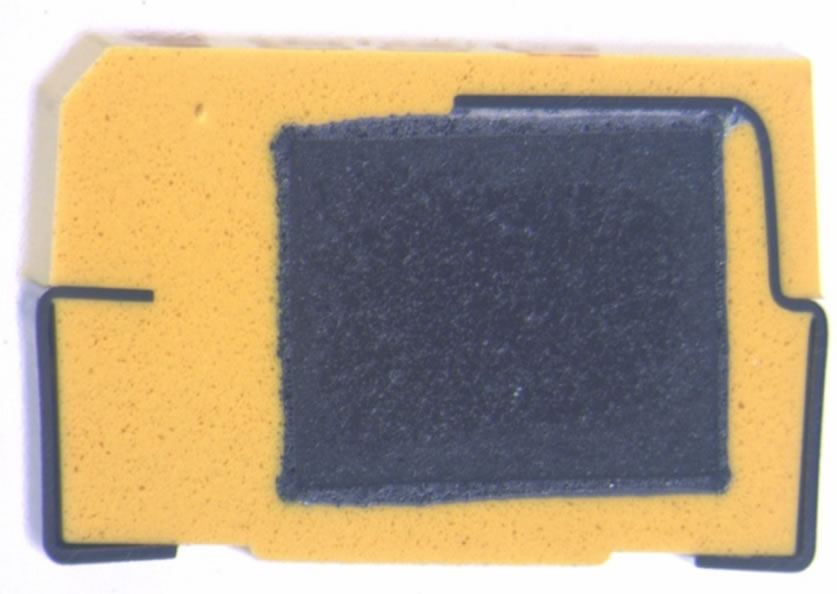
Figure 2. An example of a tested tantalum capacitor.
operating voltage of 15 V. This is the Steady-State Temperature Humidity Bias Life Test (known as the 85/85 test, a commonly used accelerated test [17]) that “is performed for the purpose of evaluating the reliability of non-hermetic packaged solid-state devices in humid environments. It employs conditions of temperature, humidity, and bias which accelerate the penetration of moisture through the external protective material or along the interface between the external protective material and the metallic conductors which pass through it”. A similar 85/85 test on 36 capacitors was run with a small modifycation of added 100 mV ripple voltage. The ripple voltage frequency was 100 Hz, and the waveform was traingular, which is closest to the ripple voltage in normal use. Test conditions, number of failed capacitors and number of tested capacitors can be seen in Table 1. These tests and the effects of ripple voltage on tantalum capacitors are more accurately described in [18]. Tantalum capacitors on a test board can be seen in Figure 3. In the first test, none of the tested 36 tantalum capacitors failed during 2500 hours. Obviously, a standard 85/85 test did not represent a stress high enough for the tantalum capacitors to fail. In the second test, out of the 36 tested capacitors, 21 failed during the first 500 hours of testing, testifying to a failure rate considerably increased by the slight modification of the standard test. Ripple voltage is a common inconvenience in electronics and since the standard 85/85 test does not take into account its effects, a modification was needed. According to these results, use of these tantalum capacitors in this kind of application is not an option.
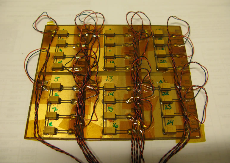
Figure 3. Tantalum capacitors on a test board.
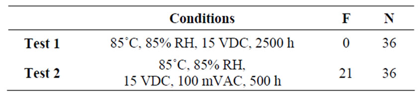
Table 1. Test conditions, number of failures, and number of tested capaci-tors.
Thus, instead of trusting blindly on standard tests, accelerated tests for WSN hardware should be carefully planned and tailored for each device, based on its structure and conditions of use. Sometimes, with minor modifications, standard tests can be diversified into various types of tests: additional stresses can be added, testing time or stress levels can be changed, etc.
6. Testing at Component Level
In a WSN, even a single node is a “system-in-package”, a highly heterogeneous collection of electronic and mechanical components, typically encapsulated into a small volume. Thus, a WSN node can be a collection of subsystems which, in turn, are collections of components. Frequently, a component-level reliability test is performed to characterize a product’s reliability, since full product-level test units are unavailable [5]. In addition, it is often impractical to test the reliability of a device as a whole. However, the relationship between a device and its components is often oversimplified and misunderstood. Such results have undesirable affect on reliability predictions and add little value to engineer [5,16]. Sometimes terribly wrong conclusions are presented and actions are based on them. For example, if all the components have 97% reliability at a given time, this does not mean that the reliability of the device is 97% at that time. The reliability of the device is often analyzed via the reliability of its subsystems and components and is dominated by the least reliable components. However, the same component used in a different location of a device can have a very different reliability estimate. Next, a real life example is presented.
A Real Life Example
Figure 4 shows the temperature distribution in an operating device, measured with a thermal imaging camera. The image shows that in the middle of the board, the temperature is about 8˚C above the board surroundings. Since the components interact with nearby components and also heat nearby components, the results from the isolated component tests may significantly differ from the field use results.
7. Testing Prototypes
Seriously incorrect conclusions can result from an accelerated test if the tested devices differ from actual manufactured devices. Manufacturing conditions and cleanlyness in a factory are usually different than those in a test laboratory. Materials and parts in prototypes may differ from those that will be used in actual production. Tested devices in an accelerated test should be taken from actual or simulated production conditions using all the same materials and parts that will be used in manufacturing. Also, manufacturing processes should match, in order to reflect variability that is present in actual production [6,7]. It is also necessary to closely monitor how the device’s reliability changes as the design changes and not to draw direct conclusions based on test results of earlier designs. Next, a real life example is presented.
A Real Life Example
We examined devices that had 4 ceramic capacitors (maximum voltage of 50 V, capacitance of 10 μF). Those ceramic capacitors were meant to be replaced with 4 tantalum capacitors (maximum voltage of 50 V, capacitance of 10 μF, shown in Figure 2). This kind of small change from ceramic to tantalum capacitors is often made very late, when reliability tests and analyses are already done. Thus, the effects of component change are unknown until actual field use of the WSN devices.
These devices were to be used in conditions that have extremely high humidity. In addition, we knew that there will be voltage onand off-periods, which is common for electronic devices in the field and also often the case with WSN devices. We did a test in order to investigate the reliability of ceramic and tantalum capacitors by enhancing the stress effect of moisture with voltage on/offperiods. This test and its results are explained more detailed in [19].
10 devices with ceramic capacitors and 10 devices with tantalum capacitors were tested with a modified 85/85 test: A standard 85/85 test with an operating voltage of 15 V was done for the first 1620 hours. A voltage cut-off of 70 hours was done after 1620 hours, after which the test continued for 310 hours (total testing time was 2000 hours).
There were 9 failures out of the 10 tested devices with tantalum capacitors (an example of a tantalum capacitor failure right after the voltage cut-off shown in Figure 5).
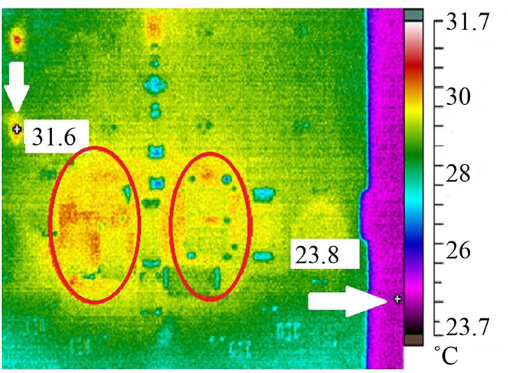
Figure 4. Thermal image of a circuit board.
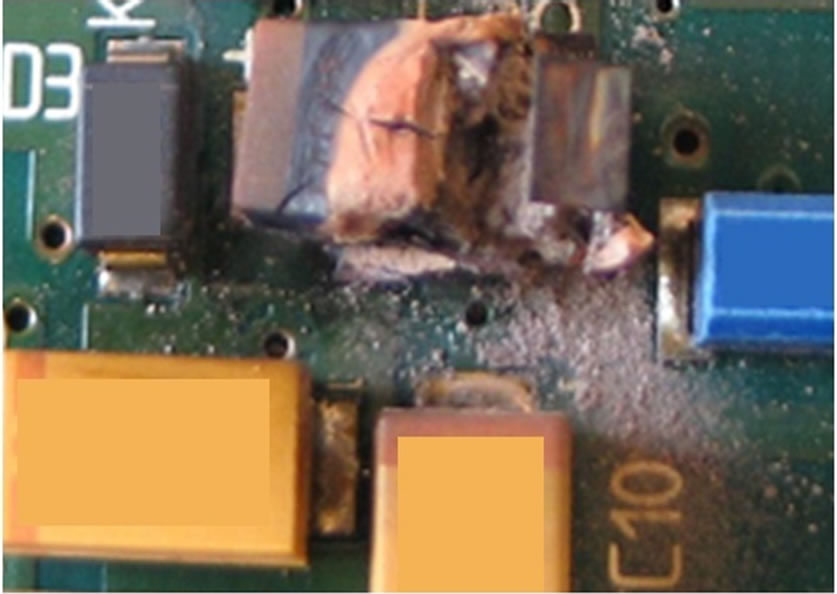
Figure 5. Failure of a tantalum capacitor.
There were 0 failures out of the 10 tested devices with ceramic capacitors.
On the basis of the results and failure analysis, it was found out that ceramic capacitors outlasted the tantalum ones since the tantalum capacitors were noticed to absorb moisture during the off-period. It would have been a terribly wrong decision to replace those ceramic capacitors with tantalum capacitors in this kind of field environment.
8. Conclusions
This paper introduced three challenges that engineers may experience in qualitative accelerated testing of WSN hardware:
1) Challenges in use of standard accelerated tests.
2) Challenges in component-level testing.
3) Challenges in testing of prototypes.
In accelerated testing of WSN hardware, devices must always be tested according to actual use environment. Standard tests can be used as a starting point, but often there is a need for modifications. All stresses that a particular WSN device is subjected to in the field should be considered when testing the reliability. The relationship between a device and its components is often oversimplified and misunderstood. Sometimes terribly wrong conclusions are presented and actions are based on them.
In addition, making changes to product after reliability analysis can invalidate everything. Seriously incorrect conclusions can result from reliability analysis if the tested products differ from actual fielded products. Results from real life reliability research were presented to clarify introduced challenges.
9. Acknowledgements
J. Virkki would like to thank the Vilho, Yrjö and Kalle Väisälä Foundation and Emil Aaltonen Foundation.
10. REFERENCES
- Commission of the European Communities, “Internet of Things—An Action Plan for Europe,” 2009. http://ec.europa.eu/information_society/policy/rfid/docments/commiot2009.pdf.
- R. van Kranenburg, “Internet of Things Europe,” Conference Report, 2010. http://ec.europa.eu/information_socety/policy/rfid/documents/iotconferencereport2010.pdf
- W. Dargie and C. Poellabauer, “Fundamentals of Wireless Sensor Networks: Theory and Practice,” John Wiley & Sons, New York, 2010. doi:10.1002/9780470666388
- M. Hempstead, M. J. Lyons, D. Brooks and G.-Y. Wei, “Survey of Hardware Systems for Wireless Sensor Networks,” Journal of Low Power Electronics, Vol. 4, No. 1, 2008, pp. 1-10. doi:10.1166/jolpe.2008.156
- Weibull Reliability Engineering Resource Website. www.weibull.com
- W. Q. Meeker and L. A. Escobar, “Pitfalls of Accelerated Testing,” IEEE Transactions on Reliability, Vol. 47, No. 2, 1998, pp. 114-118. doi:10.1109/24.722271
- W. Q. Meeker and L. A. Escobar, “Statistical Methods for Reliability Data,” John Wiley and Sons, New York, 1998.
- W. G. Ireson, C. F. Coombs and R. Y. Moss, “Handbook of Reliability Engineering and Management”, McGrawHill, New York, 1996.
- W. Nelson, “Accelerated Testing—Statistical Models, Test Plans, and Data Analyses,” John Wiley & Sons., New York, 1990.
- M. J. LuValle, “Identifying Mechanisms That Highly Accelerated Tests Miss,” IEEE Transactions on Reliability, Vol. 56, No. 2, 2007, pp. 349-359. doi:10.1109/TR.2007.896682
- E. Suhir, “Accelerated Life Testing (ALT) in Microelectronics and Photonics: Its Role, Attributes, Challenges, Pitfalls, and Interaction with Qualification Tests,” Journal of Electronic Packaging, Vol. 124, No. 3, 2002, pp. 281-291. doi:10.1115/1.1486470
- J. Virkki, P. Raumonen and L. Sydänheimo, “Modifications of the 85/85 Test and the Temperature Cycling Test for Tantalum Capacitors,” Soldering & Surface Mount Technology, Vol. 23, No. 3, 2011, pp. 168-176. doi:10.1108/09540911111146926
- J. Barret, “Challenges for Hardware Reliability in Networked Embedded Systems,” In: K. Delaney, Ed., Ambient Intelligence with Microsystems—Augmented Materials and Smart Objects, Springer, New York, 2008.
- L. L. Mercado and B. Chavez, “Impact of JEDEC Test Conditions on New-Generation Package Reliability,” IEEE Transactions on Components and Packaging Technologies, Vol. 25, No. 2, 2002, pp. 204-210. doi:10.1109/TCAPT.2002.1010007
- M. Huo, et al., “A Case Study of Problems in JEDEC HBM ESD Test Standard,” IEEE Transactions on Device and Materials Reliability, Vol. 9, No 3, 2009, pp. 361- 366. doi:10.1109/TDMR.2009.2027124
- S. Jayatilleka and O. G. Okogbaa, “Accelerated Life Testing for Speedier Product Development: Problems and Strategies,” Proceeding of the Reliability and Maintainability Symposium, Newport Beach, 23-26 January 2006, pp. 318-324.
- JEDEC Standard, “Steady State Temperature Humidity Bias Life Test,” JESD22-A101B, JEDEC Solid State Technology Association, Arlington, 2009.
- J. Virkki, T. Seppälä, L. Frisk and P. Heino, “Accelerated Testing for Failures of Tantalum Capacitors,” Microelectronics Reliability, Vol. 50, No. 2, 2010, pp. 217-219. doi:10.1016/j.microrel.2009.11.006
- J. Virkki and P. Raumonen, “Accelerated Tests for the Effects of Power Cycling on Tantalum Capacitors in a Humid Environment,” Journal of Microelectronics and Electronic Packaging, Vol. 7, No. 2, 2010, pp. 111-116.