Energy and Power Engineering
Vol. 4 No. 6 (2012) , Article ID: 25082 , 14 pages DOI:10.4236/epe.2012.46062
Simulation the Wind Grid Code Requirements for Wind Farms Connection in Kosovo Transmission Grid
1Faculty of Electric Engineering and Computer Sciences, University of Pristina, Pristina, Kosovo
2KOSTT—Kosovo Transmission System and Market Operator, Pristina, Kosovo
3Faculty of Mathematical and Natural Sciences, University of Pristina, Pristina, Kosovo
Email: *skenderkabashi@yahoo.com
Received September 14, 2012; revised October 18, 2012; accepted October 29, 2012
Keywords: Impact on the Grid of Wind Parks; Fault Ride Through; PSS/E Dynamic Simulation; Wind Grid Code; Wind Turbine Generators
ABSTRACT
This paper presents aspects of study and simulation approach for planned wind power projects in Kosovo Power System in relation with Grid Code requirements. All generators, connected to the Kosovo Transmission System are required to comply with the Grid Code. The Grid Code was originally developed with conventional synchronous generators. Since Wind Turbine Generators don’t have the same characteristics as synchronous generators, it was considered appropriate to develop a new set of Grid Code provisions specifically for Wind Farm Power Stations in relation with specific characteristic of Kosovo Power System. With high excepted penetration of wind power, a simultaneous loss of Wind Farms generation will put in the risk the security and reliability of Power System. Therefore, the main requirements for Wind farm power stations concern the fault ride through capability, frequency operation range, and reactive power capability of wind turbines. In the case of grid faults wind turbines have to supply a definite reactive power depending on the instantaneous voltage level of connection point and they must return quickly to normal operation.
1. Introduction
Penetration of wind energy in power systems in the world is steadily increasing. Because of the limited extension of the power system, this process in Kosovo is particularly challenging. In view of the increasing interest in connecting wind farms to the Kosovo electricity grid, KOSTT (Kosovo Transmission System and Market Operator) initiates to modify or extend its own Grid Code to accommodate the particular capabilities and requirements of wind turbine generators (WTGs) [1-4]. There was also a recognition that wind farm developers would benefit from a guide to the technical performance required of their plant when connected to, and operating in, the Kosovo electricity system and participate in the electricity supply market. The authors were therefore requested to review the existing Grid Code, and recommend changes or additions that would address the different technical characteristics of wind generation technology, and that would be consistent with current best practice of other TSOs (Transmission System Operators) who have developed Grid Codes to accommodate windpowered generation. Specific case study is analyzed in order to identify the main requirements for wind farm connection in Kosovo transmission grid.
2. Overview of Wind Grid Code Requirements
2.1. Detailed Technical Data
The main issue here is the obligation the Wind Code places on the Generator/developer to provide a computer model of the WTG suitable for power system studies [5]. Some TSOs prefer to develop such a model themselves, directly from a detailed mathematical description of the WTG. This, however, throws a burden of responsibility onto the TSO to get the model right—which is impractical given the present state of modelling knowledge, as well as manpower-intensive. Therefore KOSTT follows the practice of many other TSOs, and puts the obligation onto the developer. In practice, we cannot expect wind farm developers to have the knowledge or skills to produce such a model—it will probably be provided by the wind turbine manufacturer (which in turn opens up confidentiality issues). In the case where the wind farm developer can not provide WTG model, then KOSTT will use generic user models provided by the PSS/E (PTI).
2.2. Wind Farm Control
Many TSOs in their Grid Codes place a mandatory requirement on wind farm operators to control or regulate their active power output to a level set by the TSO or self-nominated—this despite the limited and intermittent capability of their generating resource. This is a very stringent requirement liable to be contested by developers—although it can be justified in certain cases (island systems, exposure to high winds, high wind power penetration, etc.). If we take as reference previous application for connection of 140 MW wind generation in transmission and limited potential of wind, this is not yet necessary in Kosovo. What is needed is a means of smoothly reducing wind farm output in response to a signal from the TSO, and of shutting it down completely under specified system conditions. Also, given KOSTT’s obligation to balance the system and to manage its area control error, it is reasonable to require wind farm operators to make an accurate forecast of output. Under the present market rules, its output nomination is made up 36 hour before delivery, which given the variability of wind speed will not be as accurate as a forecast made just before real time. This leads to a requirement that the wind farm active power control should provide a revised output forecast some short time 60 min before real time, sufficient to allow the TSO to take possible corrective action in the balancing mechanism. Because wind farms may be unmanned, the active power control must be capable of operating in automatic mode.
2.3. Frequency Control
Wind Code does not require wind farms to provide a mandatory frequency-sensitive response. The reasons for this are partly technical and partly financial. Most modern variable speed WTGs control their blade pitch to maximise the generated output at the prevailing wind speed. In order to provide the ‘headroom’ to increase output in response to low system frequency, they would have to operate at a sub-optimal blade pitch, which would require a fundamental change to their pitch control software, with implications for both initial cost and the value (to the operator) of lost output. Even if such a control were implemented, the service should be offered at a cost-reflective price: in which case the TSO is unlikely to accept it if cheaper alternatives are available. There is no present need for KOSTT to make this mandatory. Wind farms are however required to provide a high-frequency response, reducing and ultimately shutting down their output if the frequency goes high. The only credible circumstance where this might be needed is where the Kosovo system (possibly with neighbours) becomes islanded from the ENTSO/E synchronous grid in a situation of significant export. All WPGS should be able to ramp down station output proportionately to the system frequency deviation above 50.05 Hz and to reduce output to zero when the frequency exceeds 51.5 Hz. Also, all WGPS are required to initiate shutdown of station output when system frequency goes below 47.5 Hz. The frequency range over which Primary Control response is required is (49.95 - 50.05) Hz. The overall frequency characteristic of the active power control scheme is as shown in Figure 1.
2.4. Wind Farm Reactive Power Control
This is a common requirement in all TSO Grid Codes relating to wind. Given that wind farms are likely to be located in the less-populated (and so less well-connected) parts of Kosovo, it is essential that they are able to control the reactive power delivered to the grid with a reasonably broad range, in order to allow the grid operator to maintain a good voltage profile for the wind farm and local grid users. This may be a greater issue for distribution grid, and again transmission system operator should liaise with them. In this context, it should be noted that the reactive power source of WTGs has no dynamic “overload” capability—unlike that obtained from synchronous generator excitation systems, which is important in ensuring correct protection operation. Hence the need to specify such a range of reactive power capability (typically ± 33% of the wind farm nominal rating), and the requirement that reactive current be maximised during and post faults. If the reactive power control is provided via switched capacitor banks, care should be taken to ensure that step changes in voltage are not excessive, an do not affect other users. Each Wind Powered Generating Station to which this code applies shall be provided with a Reactive Power control system capable of controlling the reactive power delivered to, or the power factor measured at its Connection Point within the limits indicated in Figure 2 over the full range of Active Power
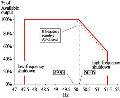
Figure 1. WPGS frequency response characteristic.

Figure 2. WPGS reactive power capability with respect to active power range.
output of the WPGS, when the voltage at the Connection Point is at within the range 97% - 103% of its nominal value.
In Figure 3 is shown Voltage/Reactive Power control characteristic and Reactive Power capability with respect of Active Power range. The area enclosed within points ABCDEFGH defines the Reactive Power capability range within which the WTGS is required to operate. The segments AH and DE represent the limits on reactive power capability imposed by the maximum value of the quadrate current, Iqmax. The voltage set-point of the characteristic shall be adjustable between (typically) 0.95 and 1.05 pu, and its slope (the change in voltage, based on nominal, that results in a change of reactive power from 0 to Qmin or 0 to Qmax) of between 2% and 7%.
2.5. Fault Ride through Capability
Fault Ride Through (the ability of WTGs to remain connected and operating for a range of grid faults) is mandatory in most TSO Grid Codes dealing with Wind, and is practically a standard feature of “second-generation” WTGs. There may be more of a problem in ensuring that smaller wind farms that use the earlier technology constant-speed WTGs turbines can comply with this requirement. All WTGs in a Wind-Powered Generating Station (WPGS), shall be provided with a Fault Ride Through (FRT) protection scheme with a Voltage/Time characteristic as illustrated in Figure 4. The FRT scheme shall be capable of retaining the WTG synchronized to the WPGS collection grid and to the transmission or distribution grid for faults anywhere in the Kosovo electricity grid so long as the voltage drop measured at the WPGS Point of Connection during the fault and during post-fault recovery remains above the solid line for the time duration indicated by the horizontal axis.
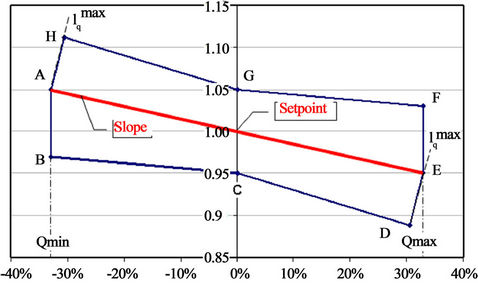
Figure 3. WPGS voltage/reactive power control characteristic.
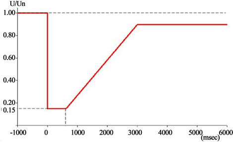
Figure 4. Fault ride through capability of WTGs.
3. Study Case: Simulation of Grid Code Compliance of 80 MW Wind Farm
The study was carried out on a large scale PSS/E model. The model consists of three simulation data files: power flow data, dynamic data and sequence data. With the aim of investigating the compliance of wind farms connecting to the Kosovo transmission grid with the Grid Code (Wind), the study considered the 80 MW wind farm project application for the so called “Shtime” area which is known to have a very high potential of wind energy [6]. The developer proposed doubly-fed induction generator (DFIG) type wind turbine technology. The wind farm is planned to have 40 wind turbines, each rated at 2 MW. This paper reports on the results of the dynamic studies carried out to demonstrate the compliance of a wind farm to the Wind Grid Code Requirements with main focus in fault ride-through requirements.
3.1. Modeling the Wind Farms
The connection configuration of wind farms to the transmission grid is based on the requirements of the Grid Planning Code and Wind Code [7]. A deterministic approach based on power flow studies is chosen. The selected connection configuration for the study case is based on two main planning criteria: the N-1 Security criterion (System should be able to withstand the loss of any single component-like line, transformer, cable or generator) and the Economic criterion.
Power flow calculation is fundamentally important for the planning and design of the connection of wind farms to the transmission grid. N-1 Security criterion is essential for the proper design of transmission grid to ensure the security and reliability of power supply. System performance is compared to operating limits and criteria. Short Circuit calculations also play a very significant role for the proper selection of high voltage equipment and the setting of protection relays. In Figure 5 is shown the configuration of wind farm connection to the 110 kV transmission grid for the study case. The Wind Farm Collector 35 kV bus is connected via two 63 MVA power transformers to the 110 kV transmission bus bar. The power generated by the wind farm will be evacuated through two 110 kV lines each thermally rated at 114 MVA.
3.2. Modeling for Steady State and Dynamic Analysis
The power system modelling, including wind turbines, for steady state analysis in PSS/E version 33 is fairly simple, as shown in Figure 6. Each individual wind
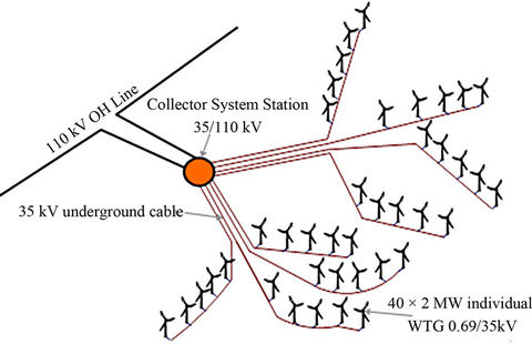
Figure 5. Connection of 80 MW wind farm project “Shtime” in transmission grid.

Figure 6. PSS/E aggregated model of 80 MW wind farm connected in transmission grid.
turbine generator (WTG) is connected to a 690 V bus, and the WTGs are connected to the wind farm internal grid through their 0.69/35 kV step-up transformers. The internal grid is organized in eight rows or sections with five WTGs in each section. Within the rows, the wind turbines are connected through 35 kV underground cables of different lengths and capacities depending on the location of each unit and the distance to the 35 kV collector bus. Power flow modelling data for the wind farm are given in Tables 1-4. The load flow solution provides the initial conditions for subsequent dynamic simulations. The maximum and minimum limits of active and reactive power must be respected in order to achieve a successful initialization. Inconsistencies between the power flow and the dynamic model will result in an unacceptable initialization [8]. For the study case winter peak demand were considered for the base case scenario [9]. In addition, 80 MW of wind farm generation was included in the model.
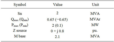
Table 1. Wind turbine generator data.
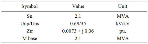
Table 2. Wind turbine transformer data.
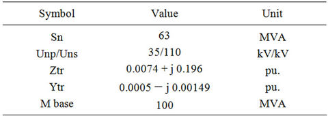
Table 3. Substation transformer data.
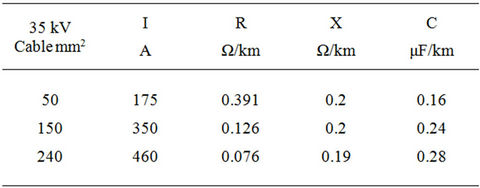
Table 4. 35 kV cable data.
3.3. Steady State Analysis
A power flow acalculation is carried out to determine the power flows on transmission lines and transformers and the voltage profile of system busses. The power flow simulations showed that some of the WTGs absorb different amounts of reactive power, depending on the WTG terminal voltage level, and on the different length and capacitance of the 35 kV connection cables. In total as is shown in Table 5 the wind farm internal grid (without power transformers) absorbs 1.6 MVAr of reactive power, with total active power losses of 1 MW at maximum wind farm power output. For the normal condition of system operation no transformer or line in the transmission grid was overloaded. The voltage profile complies with Grid Code requirements.
An N-1 contingency assessment calculation was done to check the system security, with the result that no transformer or line in the transmission grid was overloaded for any contingency. Wind Farm connection with two 110 kV lines ensure N-1 security criterion in the case when one line is tripped due to unplanned or planed outage.
Short circuit calculation is done to check the level of short circuit currents (three phases and one phase to ground) at the 110 kV connection point of the WPGS in order to determine equipment capability. The maximal value of fault currents is three phase short circuit current of 17 kA.
Based on power flow and short circuit calculations, the connection of 80 MW wind farm has no negative impact on the security and reliability of the transmission system: on the contrary, the injection of active power into the 110 kV grid so far removed from other generation sources has a beneficial impact by virtue of unloading some of the 110 kV grid and reduction of transmission power losses.
3.4. Modeling for Dynamic Analysis
A dynamic model data file for the regional (South East Europe) large scale power system is used for the study case. It contains the dynamic parameter data for all conventional synchronous generators, turbines, exciters,
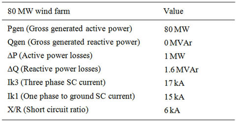
Table 5. Power balance of WPSG and fault currents.
governors and other devices in the regional system. The first step in the PSS/E dynamic simulation is to enter the detailed dynamic model data for the wind farm, which is saved in a file. This file comprises a group of records, each of which defines the location of a dynamic WTG model in the grid along with the model parameters. Dynamic simulation was performed based on the power flow data that provide the transmission grid, load, and generator data. In this study, a number of simulations are performed to investigate the WTG model response to grid disturbances. The most significant disturbance for the study is a three-phase symmetrical short-circuit fault on the 110 kV connection bus as shown in Figure 6. Additional faults are simulated on other busses of the Kosovo transmission system, in order to assess WTG dynamic behavior for a range of fault impedances.
3.5. PSS/E Dynamic Model of DFIG
As size of wind turbines has become larger, the technology has switched from fixed speed to variable speed. The drivers behind these developments are mainly the ability to comply with Grid Code connection requirements. The variable speed wind turbine using DFIG technology is used worldwide, due to its many advantages such as high energy efficiency and controllability. PSS/E versions 31 - 33 provide a dynamic model for a DFIG-type wind turbine, including representations of the generator, electrical control, and wind turbine and pitch control modules. The DFIG is basically a standard wound-rotor induction generator with slip rings to take current into or out of the rotor winding and variable speed operation is obtained by injecting a controllable voltage into the rotor at slip frequency. The rotor winding is fed through a variable frequency power converter, typically based on two AC/DC IGBT-based voltage source converters linked by DC bus as shown in Figure 7. The stator winding is coupled directly to the wind farm internal grid via each WTG’s step-up transformer [10,11].
The PSS/E wind turbine model WT3 is used for the dynamic simulation study with the objective of simulating the dynamic performance of a wind turbine employing DFIG technology. The generic WT3 model is
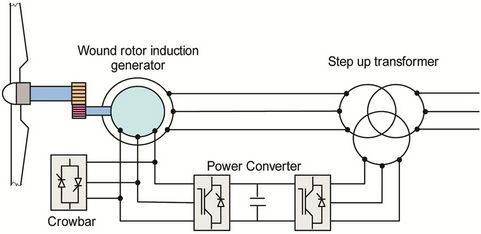
Figure 7. Double-fed induction generator.
included as a standard model in the Dynamic Model Library of PSS/E versions 31 - 33 [12,13]. The WT3 model can only be used when the generator is specified as a wind generator and not a conventional generator in the power flow data file.
The WT3 generic wind turbine model consists of the following main modules: WT3G generator/converter module, WT3E electrical control module, WT3T turbine module and WT3P pitch control module. The interaction between these modules is illustrated in Figure 8. Tables 6-9 show the dynamic data for a 2 MW, DFIG based on the WT3 generic wind turbine model.
4. Dynamic Simulation Results and Discussions
Transient stability is the ability of the power system to maintain in synchronism when subjected to severe tran-
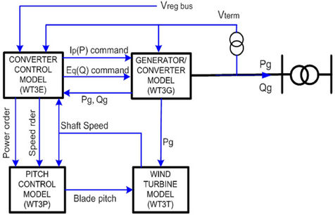
Figure 8. PSS/E DFIG generic model.
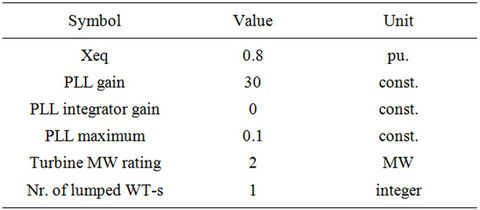
Table 6. WT3G1 generator model data.
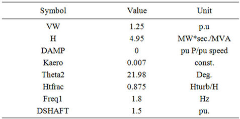
Table 7. WT3T1 wind turbine model data.
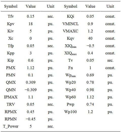
Table 8. WT3E1 wind turbine electrical model data.

Table 9. WT3T1 Pitch model data.
sient disturbances. Stability depends on both the initial operating state and the severity of the disturbance. Looking at it from the point of view of steady state operation, wind power is like any other type of power generation. However, the behavior of wind turbines during and after disturbances is different from that of conventional generators [14]. The disturbances which are usually analyzed in transient stability studies are three phase and one phase to ground short circuits. They are usually assumed to occur on the transmission line. The fault is cleared by tripping the faulted line to isolate the faulted line.
In our study case for all simulations, the following conditions were applied:
• The fault is a bolted symmetrical three-phase occurred on the shortest 110 kV line connected to the WPGS• The fault is applied one second after the start of the simulation.
• The fault is cleared after 180 ms by tripping the faulted line
4.1. System Stability
Kosovo Power System is strongly connected to the 400kV regional grid through three 400 kV lines and two 220 kV lines. The 97% of total generation in Kosovo Power System (TPP Kosovo B, 2 × 300 MW and TPP Kosovo A, 3 × 150 MW) are located near main substation SS Kosovo B, 400/220 kV. The impact of the faults occurred in 110 kV grid on security margin of transient system stability is minor. Figure 9 shows rotor angular response of existing conventional generators during the fault on 110 kV wind farm point of connection and trip of 80 MW Wind Park, where no significant impact on conventional generators which remain in synchronization. Figure 10 shows the system and wind turbine generator
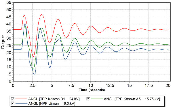
Figure 9. Rotor angular transient response of conventional generators during the fault.
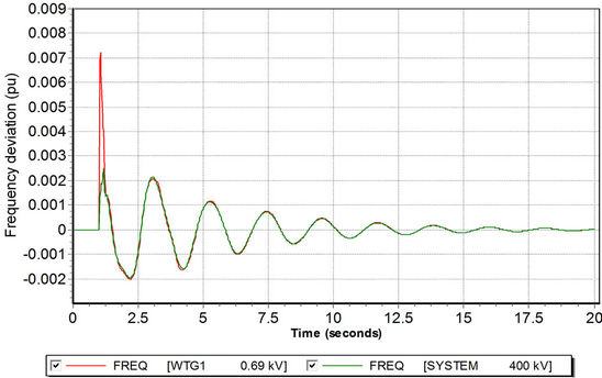
Figure 10. Frequency transient response after fault occur in the 110 kV connection line of wind farm.
frequency response during the fault for the case where Wind Park remain in operation after fault is cleared. The frequency deviation is in the stable frequency range as per Wind Grid Code Requirements.
4.2. Active and Reactive Power Response
Figure 11 shows that during the fault the WTG electrical power output for two selected wind turbine generators WTG1 and WTG5, suddenly decreases to a very low value 0.0045 pu or 0.45 MW. In total the wind farm active power output during the fault decreases from 80 MW to 18 MW. The difference between the mechanical input power and electrical output power causes an increase in the rotor speed and therefore the rotor starts to accelerate. The torsion oscillation in the drive-train model is reflected in the output power of the wind turbine. Oscillation of power output after the fault is cleared will cause mechanical stress in the drive train system. Approximately 18 seconds after the fault is cleared, the power output recovers to pre-fault value of 2 MW.
The reactive power output from two selected wind turbine generators is shown in Figure 12. Before the fault occurs, the generated reactive power is zero and the wind farm operates at unity power factor. During the fault, the rotor speed increases, giving a larger negative slip. This is because electric power has decreased to almost zero whereas mechanical power is assumed to be the same. As a result, WT3P module responds by altering the blade pitch to decrease mechanical power. Each WTG units during the fault provide reactive power support to the grid (0.0035 pu or 0.35 MVAr), as is as is required by the Wind Grid Code. In total the wind farm during the fault, inject around 18 MVAr reactive power to the grid.
4.3. Voltage Response-Fault Ride through Ability
Many types of faults may occur in a wind farm power system. In this paper, only the three-phase symmetrical fault is investigated because for the 110 kV and 220 kV transmission network of Kosovo this fault generates the highest fault current. From the point of view of location, two types of faults exist: near faults and far faults. In near faults, the voltage at the wind farm is practically zero. In far faults, depending on the impedance of the lines, cables, power transformers and network configuration the voltage at the wind farm does not drop completely to zero as is shown in simulation result. Figure 13 shows that during the fault on the 110 kV connected line (near point of connection), the voltage on 110 kV point of connection drops to zero. The WTG1 terminal voltage shows a similar pattern, except that during the fault the minimum terminal voltage is 0.23 pu, which is considerably higher than the faulted connection point voltage. The range of terminal voltage drop to other 40 WTG’s is from 0.23 pu to 0.25 pu, depending on installed location of units. The voltage drop on 35 kV collector bus is 0.11 pu. After fault clearance, when the faulted line is disconnected from the grid, the voltage at both locations (110 kV and 35 kV) recovers to around 0.97 pu. for approximately 1.4 sec. Corresponding to the technical requirements from Wind Grid Code regarding to the fault right through the simulation results indicate that all 40 DFIGs do not have the ability to ride through the fault for the short circuit occurred near point of connection. For other faults occurred in transmission network the voltage drop is above minimum permitted value 0.15 pu. Additional series of bus fault simulation is done to investigate voltage drop dependences from various bus fault impedances. Figure 14 shows WTGs terminal voltage response for three different fault events, each with different fault impedances. The most critical case for the WTGs is when the fault occurs on the POC (point of connection) or near of POC where the voltage drop at POC is below 0.15 pu. In those cases the corresponding voltage drop is not in compliance with actual Kosovo Wind Grid Code regarding fault ride through capability.
4.4. Speed Response
Figure 15 shows the wind turbine shaft speed and generator rotor speed response after the fault occurs. The generator speed is oscillating, with respect to the turbine speed for about 5 seconds after the fault. 14 seconds after fault is cleared, both shaft and rotor speed recover to the pre fault value after some 14 seconds. As can be seen in Figure 16, the turbine blade pitch angle is increased during the fault in order to reduce the power input from the wind turbine. The pitch angle is oscillating in response to the oscillation of the speed of the turbine. For a few seconds after fault clearance, the turbine shaft speed decreases while the pitch angle increases due to the effect of pitch compensation controller tending to reduce the input power to the turbine by increasing the pitch angle.
5. Reviewing the Fault Ride through Ability of Kosovo Wind Grid Code
The requirements for low voltage ride through in the Kosovo are expressed differently to the corresponding requirements found in other grid codes making a direct comparison difficult. Figure 17 shows the envelope of permitted voltage ride through requirements for transmission connected wind farms in the ENTSO-E draft connection code and in other different countries grid codes [15-19].
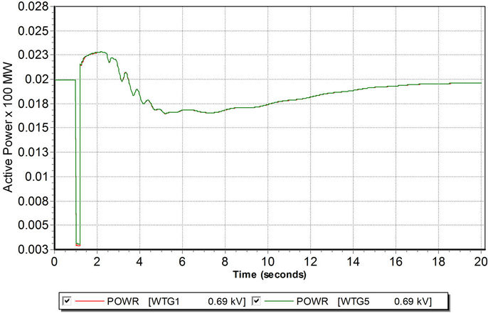
Figure 11. WTG active power response after fault.
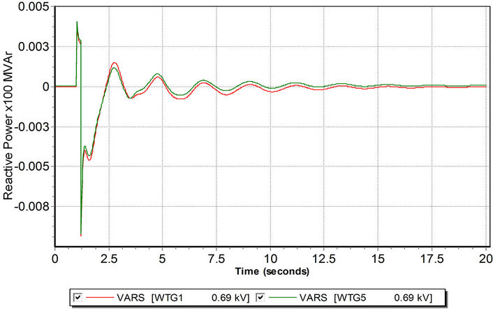
Figure 12. WTGs reactive power response for two selected units WTG1 and WTG5.

Figure 13. Voltage response after fault occurrence in the 110 kV connection line of wind farm.
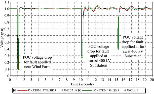
Figure 14. Series bus faults with different fault impedances.
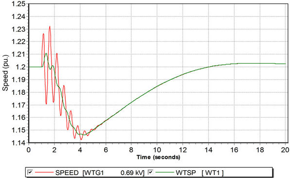
Figure 15. Wind turbine speed and generator speed response.
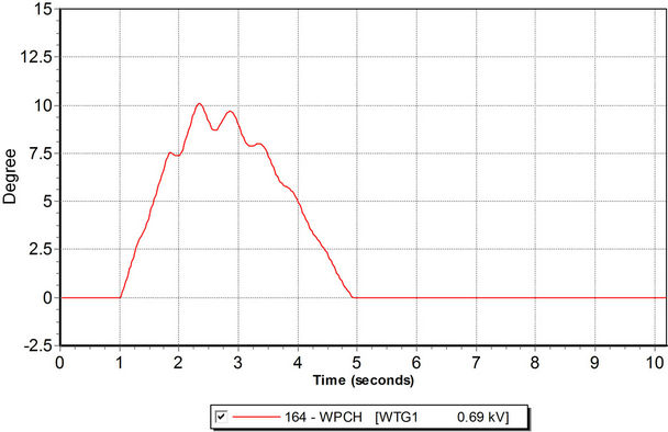
Figure 16. Pitch angle response after fault event.

Figure 17. Summary regarding fault ride through capability of wind turbines in National Grid Codes.
Kosovo fault ride through requirement almost is similar to the Ireland’s grid code and they are very demanding in respect with the fault duration, but not sufficient for faults very near to POC where the voltage can drop down to 0%. Denmark has the lowest short circuit time duration with only 100 ms. However, Denmark’s grid code requires that the wind turbine shall remain connected to the electrical network during successive faults. The German grid code and ENTSO/E draft connection code requires to wind power installations to remain connected during voltage drop down to 0% from the rated voltage in the POC for a duration of 150 msec. Each country’s power system is characterized with different structure and behavior such as network configuration, system voltage levels, short circuit current levels, transient stability margin, voltage stability margin, relay system protection selectivity and settings etc. therefore decision for the proper fault ride through requirements is not an easy task.
Three main factors determine the fault ride through voltage profile envelope:
• Total fault clearing time targets
• Post fault voltage recovery (duration and level)
The first factor depends directly from the relay protection and high voltage circuit breaker technology installed in each national power system. The relay protection systems (relays, auto-reclose, pilot protection, event recorders, etc.) and its proper selectivity play a significant role regarding fault ride through ability of wind farms. In Table 10 is shown the maximum fault clearance times as per KOSTT Electrical Equipment Code [20]. The total fault clearing time target of main in-feed circuits is 150 ms. Taking in consideration that during last 5 years, 90% of old electromechanically and electrostatic relays are replaced with new fast speed numerical relays, the total fault clearing time less than 150 ms is reasonable.
The second factor is influenced from the power system characteristic. The Kosovo power system is relatively small but strongly interconnected and tightly meshed. Most short circuit power is supplied by synchronous generating units connected to the power system. Wind generation technologies may provide less short circuit power capability than synchronous generating units. Based on planned development of new generation capacities increase of system short circuit power will increase the power system’s ability to support the system voltage during short circuit faults and to reduce the post fault voltage recovery time. For the voltage drop observed at 110 kV buses for the fault with 180 ms complete fault clearance time the voltage recovers to 97% for approximately 1.4 s (Figure 13). The new proposed post fault voltage recovery time of 1.5 s, similar to ENTSO/E and German requirements is appropriate for Kosovo Transmission System Operator.
The actual envelope of the fault right through requirements for new installed WT is not sufficient to prevent negative impact of tripped wind turbines in the Kosovo Transmission System. Therefore new envelope for fault right through capability is proposed as is shown in Figure 18 and summarized in Table 11. The new technology of wind turbine generators with installed fault right through protective schemes (crowbar protection), could remain in operation for the voltage drop down to 0.0% for a short time <150 ms, which is a sufficient fault clearing time corresponding with nowadays fast speed relay protection and fast HV SF6 circuit breakers.
6. Conclusion
In this paper aspect of transmission system analysis and planning in Kosovo Power System with relatively large wind capacity have been described. The proper and detailed modelling of wind farm projects in system studies is becoming increasingly important to system operators. A specific case study is analysed in order to identify the
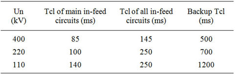
Table 10. Maximum fault clearance times (Tcl) as per electrical equipment code (KOSTT).
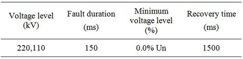
Table 11. New proposed fault ride through requirements.
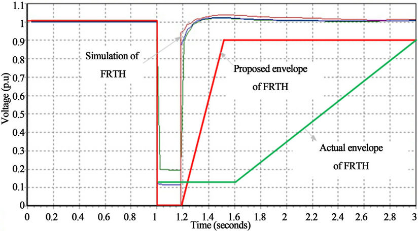
Figure 18. The new proposed envelope for fault ride through for Kosovo Wind Grid Code.
main technical requirements for wind farm connection in transmission grid. Power flow, short circuit and dynamic analyses are carried out in order to check the influence of the wind farm on the transmission system in respect of the Grid Code requirements. The PSS/E wind turbine stability generic model WT3 is used for the dynamic simulation with the objective of simulating the dynamic performance of DFIG technology WTGs. The overall conclusion of these analyses is that the wind farm does have an influence on the transmission system but all of the requirements of the Grid Code relating to the wind farm connection were satisfied except fault right through capability for the short circuits occurred near the point of connection. Therefore new envelope for voltage profile during the fault occurrence is proposed. As the penetration of wind power onto the Kosovo power system increases, the dynamic behaviour of the power system is increasingly affected. The main concern of operating with a high level of penetration of wind generation in the Kosovo power system is related to the impact of wind power variability on the power system balance, given the current shortage of system regulation reserves. The variability impact issue on Power System is not addressed in this paper and it will be covered in subsequent ones.
7. Acknowledgements
The author wishes to acknowledge the support of the University of Pristina, Kosovo.
REFERENCES
- S. Kabashi, S. Bekteshi, S. Ahmetaj, G. Kabashi, D. Najdovski, A. Zidanšek, et al., “Effects of Kosovo’s Energy Use Scenarios and Associated Gas Emissions on Its Climate Change and Sustainable Development,” Applied Energy, Vol. 88, No. 2, 2011, pp. 473-478. doi:10.1016/j.apenergy.2010.06.023
- A. Zidanšek, R. Blinc, A. Jeglič, S. Kabashi, S. Bekteshi and I. Šlaus, “Climate Changes, Biofuels and the Sustainable Future,” International Journal of Hydrogen Energy, Vol. 34, No. 16, 2009, pp. 6980-6983. doi:10.1016/j.ijhydene.2008.11.004
- R. Blinc, D. Najdovski, S. Bekteshi, S. Kabashi, I. Šlaus and A. Zidanšek, “How to Achieve a Sustainable Future for Europe,” Thermal Science, Vol. 12, No. 4, 2008, pp. 19-23.
- “Long Term Electricity Balance 2011-2020,” 2012. http://www.kostt.com/website/
- “Wind Grid Code,” 2010. http://www.kostt.com/website/
- “Transmission Grid Development Plan 2011-2021,” 2011. http://www.kostt.com/website/
- “Grid Code-Planning Code,” 2010. http://www.kostt.com/website/
- “PSS/E Manual Version 33,” www.energy.siemens.com/us/en/services/.../pss-e.htmCached
- The Southeast European Cooperative Initiative (SECI): Project, “Evaluation of Investments in Transmission Grid to Sustain Generation and Market Development in SEE,” 2007. http://www.usea.org
- B. Fox, D. Flynn, L. Bryans, N. Jenkins, M. O’Malley and R. Watson, “Wind Power Integration Connection and System Operational Aspects,” The Institution of Engineering and Technology, London, 2007.
- O. Anaya-Lara, N. Jenkins, J. Ekanayake and P. Cartwright, “Wind Energy Generation Modeling and Control,” John Wiley & Sons, Ltd., Chichester, 2009.
- “PSS/E 33 Wind Package, Generic WT3 User Guide.” www.energy.siemens.com/us/en/services/.../pss-e.htmCached
- G. Kabashi, K. Kadriu, A. Gashi, S. Kabashi, G. Pula and V. Komoni, “Wind Farm Modeling for Steady State and Dynamic Analysis,” World Academy of Science, Engineering and Technology, Vol. 74, 2011, pp. 262-267. www.waset.org/journals
- T. Ackermann, “Wind Power in Power Systems,” John Wiley & Sons, Chichester, England, 2005.
- “Guideline for Generating Plants Connection to and Parallel Operation with the Medium-Voltage Network,” BDEW Bundesverband der Energieund Wasserwirtschaft e.V., June 2008.
- “Eir Grid Code,” Version 3.5, 15 March 2011.
- E. On-Netz, “Grid Code. High and Extra High Voltage,” April 2009.
- F. Iov, A. D. Hansen, P. Sørensen and N. A. Cutululis, “Mapping of Grid Faults and Grid Codes,” Risø National Laboratory Technical University of Denmark Roskilde, Denmark, 2007.
- E. Entso, “Draft Requirements for Grid Connection Applicable to All Generators,” 22 March 2011.
- “Electrical Equipment Code KOSTT,” 2011. http://www.kostt.com/website/
Abbreviation
KOSTT: Kosovo Transmission System and Market Operator WTGs: Wind Turbine Generators TSOs: Transmission System Operators ENTSO/E: European Network of Transmission System Operators for Electricity PSS/E: Power System Simulation for Engineering POC: Point of Connection WPGS: Wind-Powered Generating Station DFIG: Doubly-Fed Induction Generator FRT: Fault Ride through AC/DC: Alternating (Direct) Current IGBT: Insulated Gate Bipolar Transistor MWh: Mega Watt Hour GWh: Giga Watt Hour MVA: Mega Volt Amper kV: Kilo Volt MVAr: Mega Volt Amper Reactive
NOTES
*Corresponding author.