Communications and Network
Vol. 4 No. 1 (2012) , Article ID: 17505 , 5 pages DOI:10.4236/cn.2012.41012
Layer-Wise Topology Design for Cost Effective IP-Optical Networks
Department of Computer Science and Engineering, Faculty of Engineering and Resource Science,
Akita University, 1-1 Tegata-Gakuen-Machi, Akita City, Japan
Email: hashimoto@ie.akita-u.ac.jp
Received November 4, 2011; revised December 6, 2011; accepted January 16, 2012
Keywords: IP-Optical network; Traffic engineering; Wavelength division multiplex; Linear programming
ABSTRACT
Traffic engineering and topology design considering multilayer configuration have become more important. While multilayer design studies usually discuss the traffic engineering issue or reliability, this paper focuses on network construction cost in studying multilayer topology design. The number of ports for the IP layer and the maximum number of Wavelength Division Multiplexers (WDM) for the optical layer are used as construction cost factors. Given a traffic matrix for the IP layer, 1) the number of ports is minimized to obtain a topology and a traffic matrix for the optical link, and 2) the maximum number of WDMs is minimized to configure the optical layer topology. It is shown that both the IP and Optical path layers have been given economic topologies. We present LP formulations of this scheme and the results of a simulation of the full-mesh traffic of 5 nodes, which shows that both layers are successfully optimized.
1. Introduction
The expectations placed on the IP optical network have grown with the increase in new network applications intended for broadband services, such as IP phones and stream broadcasting. It yields large-capacity and economic networks that offer IP technology for packet-bypacket routing and optical cross-connect technology for optical switching. Because this network essentially has a multilayer configuration, careful design of both layers is needed for topology establishment and traffic accommodation. While backup path reliability problems [1-3] and traffic engineering [4-6] for traffic smoothing have been actively studied recently in terms of both layers [7-9], it is seems that topologies are usually predetermined and fixed.
This paper discusses the design of both topologies. It is intended to identify the most economic topology configuration that can also accommodate the traffic. This paper is organized as follows. Section 2 introduces the problem of multilayer topology design considered here. Section 3 provides formulations and the calculation procedure to solve it. Sections 4 and 5 verify its effectiveness by a simulation that uses an example traffic matrix. Finally, we conclude this study in Section 6.
2. WDM-Based IP-Optical Network
2.1. Problem Definitions
An IP-optical network is comprised of the IP layer (logical layer) with its logical links and the optical path layer (optical layer) in which optical links are formed. Logical links between nodes in the logical layer are defined by the interfaces of the end nodes. An optical path in the optical layer realizes a logical link as a physical entity to provide its bandwidth. Each logical link uses an optical path in the optical layer. Our goal is to design economic topologies of the logical and optical layers when full mesh traffic demands between each node are given.
The following conditions are assumed here:
1) Logical layer: The number of interfaces determines the cost of the logical layer, so the total number of interfaces should be minimized. We assume that only one type of interface, such as 10 Gbps, is used.
2) Optical layer: The number of WDMs determines the cost of the optical layer, so the maximum number of wavelengths should be minimized. Each node pair linked by one optical fiber or is not linked. A WDM is used when one fiber carries more than one optical paths. Here, transparency of optical path through wavelength continuity is not considered. In other words, cross-connects with OE/EO functionality are available. Optical paths have the same bandwidth regardless of wavelength.
Figures 1 and 2 provide an example of routing of traffic and logical/optical links, respectively. Routing for two traffic demands (traffic 1, and traffic 2) in the IP layer is shown in Figure 1. In order to design a topology that can accommodate the traffic demands, it is assumed
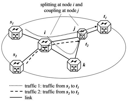
Figure 1. Routing of traffic.
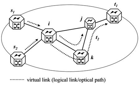
here that flow splitting and merger can be conducted in a route such as traffic 1. Figure 2 shows an example solution of the virtual links for Figure 1 where the number of ports is minimized. Virtual link means a logical link in the logical layer, or the optical path corresponding to the logical link. In this case, there are links from or to node k in Figure 1, but there is no virtual link that considers node k to be an outgoing or incoming node, i.e. having outgoing or incoming ports.
2.2. Optimizing Objects and Design Procedure
For the logical layer, the total number of ports for all nodes is used as the cost factor. It is assumed that the total cost depends on the number of ports while the installation of nodes is essential in the logical layer. For the optical layer, the maximum number of WDMs is important for cost effectiveness. It is considered that the number of wavelength paths is suitable even for the case in which the wavelength paths are implemented over existing facilities. Even in this case, it is assumed that the maximum number of WDMs is used as the cost measure since WDM device cost increases with its scale.
The design procedure in this paper has two steps:
1) Logical links with the fewest (total) interfaces are determined from nodes of the logical layer, traffic between each pair of nodes, and the bandwidth of each interface. The link capacity necessary between each pair of nodes is determined.
2) The capacity obtained in the above step is used as the input traffic, and the topology that minimizes the maximum number of WDMs between each pair of nodes is determined.
Figure 3 shows the above procedure.
2.3. Formulation of Logical Layer Design
Logical links with fewest interfaces are determined from nodes of the logical layer, traffic between each pair of nodes, and the bandwidth of one interface. We provide a LP (linear programming) formulation below. We consider logical network G(V, E) which consists of a set of nodes, V and a set of links, E.
Parameters and variables:
• (i, j): link from node i to j, (i, j) Î E.
• K: a set of traffic demands between a node pair.
• dk: each traffic demand, k Î K.
• sk, tk: source node and target node of traffic k.
•  utilization ratio of link (i, j) for traffic demand dk, real number.
• Yij: number of logical links between nodes i and j, integer.
• w: capacity per logical link.
The objective is the minimization of the total number

Figure 3. Calculation steps of proposed scheme.
of ports of logical links.
Objective function:
 (1)
(1)
subject to:
 (2)
(2)
 (3)
(3)
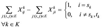
Equation (2) is the network flow conservation law [10] and Equation (3) is the condition derived from link capacity. We do not describe the formulation that contains tk here because it is redundant [11]. The route of traffic dk is described by Xijk. If Xijk is a real number (≠{0,1}), splitting and merging occur at node i and node j.
The link between node i and node j is defined by Yij and accommodates the total amount of traffic dk·Xijk in its section. Equation (3) means the relationship between traffic and capacity. The number of links needed between node i and node j is Yij. Yij should be an integer. Yij is used as the demand for traffic in the optical layer.
2.4. Formulation of Optical Layer Design
It is assumed that the optical layer does not include nodes that do not exist in the logical layer. In other words, it is assumed that all or a part of nodes in the logical layer can be used. Notation used in the logical layer is partly reused for the sake of convenience. Notations are as follows. Optical network G(V, EF) consists of a set of nodes, V, and a set of links, EF.
Parameters and variables:
• (i, j) Î EF: optical link from node i to j.
• K: a set of traffic demands between a node pair.
• dk: traffic demand for each optical path, k Î K.
• sk,tk: source node and target node of path dk.
•  : utilization ratio of optical link (i, j) for demand dk.
• Pmax: the maximum number of WDM in each optical fiber.
Here, traffic volume dk is assumed to be the same value as w. The number of traffic demands between nodes i and j is Yij and the total number of traffic demands, which is the number of elements in set K, is Σ(i,j)ÎEYij.
Constraint equations are as follows:
Subject to:
 (4)
(4)
 (5)
(5)
The objective function is the minimization of the maximum number of WDMs.
Objective function:
 (6)
(6)
3. Simulation
3.1. Simulation Conditions: Traffic Matrix
The cost239 topology [12] shown in Figure 4 is examined as a topology, and a gravity model with uniform distances is examined as a traffic matrix. A gravity model means that the amount of traffic between cities is assumed to be proportional to the population of the cities [13]. Because this is a problem of topology design, cost239 is used as reference only for node 11 and the traffic matrix.
Logical layer design is formulated as an integer problem. Therefore, the LP solution method may become infeasible if the layer is larger than a certain size. Table 1 shows the result and calculation time taken when minimizing the total number of logical ports. As calculation time increases, the number of ports is decreased, and minimization progresses. However, the LP tool, GLPK [14]1, cannot complete optimization. It additionally shows the result (the minimum total number of ports) yielded by real number relaxation.
It is considered that this optimization can be conducted for large network sizes by using high performance solvers such as CPLEX [15]. However, the main purpose here is to verify formulation and calculation steps, so, it

Figure 4. Example network: cost239.
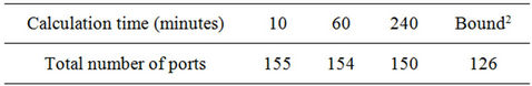
Table 1. Calculation time and obtained number of ports for logical layer.
is assumed here that calculation is limited to the extent that a solution can be directly obtained by LP. As a result of conducting the calculation while gradually increasing the number of nodes, it is found that a solution for 5 nodes or less can be obtained within a relatively short time. Therefore, the case of 5 nodes is examined.
After 5 nodes are selected from the cost239 topology, we consider a network consisting of these 5 nodes. And, only a part of the traffic matrix for the cost239 topology is used. Table 2 shows the bidirectional full-mesh traffic matrix used. Designing the links between these nodes is the problem. Here, the unit is Gbps, and the capacity per link, w in Section 2.3, is 10 Gbps.
3.2. Result for Logical Layer
Table 3 shows the simulation results of Step 1. The total number of ports is 46. Considering that the total amount of traffic is approximately 423 Gbps,3 four more ports are needed compared to the real number relaxation result. It is found that although full-mesh traffic is given, no logical links are formed from node 2 to 0, from node 0 to 3, from node 0 to 4, and from node 4 to 2.
3.3. Result for Optical Layer
Step 2, which minimizes the maximum number of WDM, is carried out. Table 4 shows the results. The table shows optical paths (implementing logical links) with the number of optical paths in parentheses. For example, logical link from node 1 to node 2, which has three ports as shown in Table 3, consists of three optical paths from node 1 to node 2. The logical links from node 1 to node 3 and from node 3 to node 1, consist of three different optical paths. One of the three paths from node 1 to node 3 in the table, “1-0-3(4)”, indicates that there are four optical paths from node 1 to node 3 via node 0. The optical path of 1-0-3 uses two optical fibers; fiber from node 1 to node 0 and that from node 1 to node 0. That is, “1- 0-3(4)” also implies four wavelengths are necessary in the fiber. Thus, it is found that the maximum number of WDMs is 5.
As described above, this procedure produces a topo-
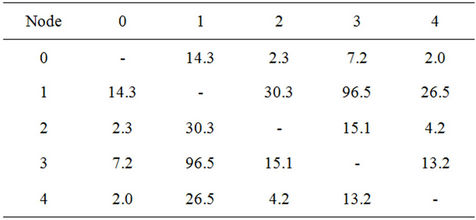
Table 2. Traffic matrix for 5 nodes network.
logy with the minimum number of ports for the logical layer (46 ports) and the minimized number of WDMs for the optical layer (5 wavelengths). Traffic through a link in the logical layer does not always coincide with traffic through the link in the optical layer. The obtained topology is shown Figure 5. The detailed number of logical connections and the number of optical paths are as shown in Tables 3 and 4, respectively.
4. Discussion: Comparison with Non-Layered Structure
It is also possible to determine a topology without consideration of the multilayer configuration. Table 5 shows
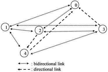
Figure 5. Obtained logical topology for 5 nodes.
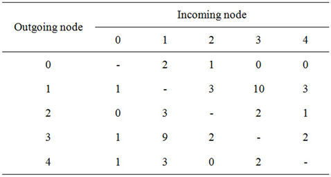
Table 3. Logical layer topology: the number of ports of each node.

Table 4. Optical layer topology: optical path and the number of wdm between each node.

Table 5. Comparison with single layer configuration.
this comparison. “Ports opt.” in the table means that the logical layer topology is also used as optical layer topology. “WDM opt.” in the table means that optical paths appearing in Table 5 are also used as links in the logical layer. In “WDM opt.”, we assume OE/EO conversion in each optical path. So, a one hop optical path such as 1-0 consists of one logical link 1-0, but optical path 1-0-3 consists of two logical links: 1-0 and 0-3. 1-0-3(4) means that there are four logical links of 1-0 and 0-3. From the table, it is found that this procedure realizes the optimization of each layer. However, the cost factor of the other layer is not optimized, unlike our scheme.
5. Conclusion
In this paper, we proposed a design method for realizing economic IP optical networks that accommodate the traffic given by the IP layer. This is a layer-wise design scheme having two steps. In step 1, the total number of ports for nodes is taken as the construction cost for the logical layer, and a configuration that minimizes this cost is realized. In step 2, the maximum number of WDMs per optical fiber is taken as the construction cost for the optical layer, and a configuration that minimizes it is realized. The traffic demand in the optical layer is determined by the configuration is obtained in step 1. We presented LP formulations of this scheme and successfully conducted simulations of full-mesh traffic with 5 nodes.
REFERENCES
- Y. Liu and D. Tipper, “Successive Survivable Routing For Node Failures,” IEEE Globecom, Vol. 4, 2001, pp. 2093-2097.
- J. Zhang, K. Y. Zhu, H. Zang and B. Mukherjee, “A New Provisioning Framework to Provide Avilability-Guaranteed Service in WDM Mesh Networks,” IEEE ICC 2003, Vol. 2, 2003, pp. 1484-1488.
- M. Clouqueur and W. D. Grover, “Availability Analysis of Span-Restorable Mesh Networks,” IEEE Journal on Selected Areas in Communications, Vol. 20, No. 4, 2002, pp. 810-821. doi:10.1109/JSAC.2002.1003046
- D. Awduche, J. Malcolm, J. Agogbua, M. O’Dell and J. McManus, “Requirements for Traffic Engineering over MPLS,” IETF, RFC 2702, 1999.
- K. Kompella and Y. Rekhter, “OSPF Extensions in Support of Generalized Multi-Protocol Label Switching (GMPLS),” RFC 4203, 2005.
- Y. Wang and Z. Wang, “Explicit Routing Algorithms for Internet Traffic Engineering,” IEEE International Conference on Computer Communications and Networks, Boston, 11-13 October 1999, pp. 582-588.
- B. Rajagopalan, D. Pendarakis, D. Saha, R. S. Ramamoorthy and K. Bala, “IP over Optical Networks: Architectural Aspects,” IEEE Communications Magazine, Vol. 38, No. 9, 2000, pp. 94-102. doi:10.1109/35.868148
- Y. Liu, H. Zhang, W. Gong and D. Towsley, “On the Interaction between Overlay Routing and Underlay Routing,” IEEE Infocom, Vol. 4, 2005, pp. 2543-2553.
- A. Elwalid, D. Mitra and Q. Wang, “Cooperative Data-Optical InterNetworking: Distributed Multi-Layer Optimization,” IEEE Infocom, Barcelona, 2006, pp. 1-11.
- R. K. Ahjua, T. L. Magnanti and J. B. Orlin, “Network Flows: Theory, Algorithm, and Applications,” Prentice Hall, Upper Saddle River, 1993.
- E. Oki and A. Iwaki, “Performance of Optimal Routing by Pipe, Hose, and Intermediate Models,” IEICE Communications Society: Transactions on Communications, Vol. E93-B, No. 5, 2010, pp. 1180-1189.
- M. O’Mahony, M. C. Sinclair and B. Mikac, “Ultra-High Capacity Optical Transmission Network: European Research Project Cost239,” Information, Telecommunications, Automata Journal, Vol. 12, No. 1-3, 1993, pp. 33- 45.
- M. Roughan, M. Thorup and Y. Zhang, “Traffic Engineering with Estimated Traffic Matrices,” IMC2003, 2003.
- http://www.gnu.org/software/glpk/
- http://www-01.ibm.com/software/integration/optimization/cplex-optimizer/
NOTES
1Calculation environment: Intel D 2.8 GHz (CPU).
2This value is obtained using real number relaxation which treats all variables of the problem as real number.
3This value is a summation of values in Table 2.