World Journal of Condensed Matter Physics
Vol.2 No.4(2012), Article ID:25038,9 pages DOI:10.4236/wjcmp.2012.24039
Model of Preformed Hole-Pairs in c-Axis Transport in Cuprate Superconductors
![]()
Department of Physics, Aligarh Muslim University, Aligarh, India.
Email: ranajsingh@yahoo.com
Received August 23rd, 2012; revised September 26th, 2012; accepted October 3rd, 2012
Keywords: Cuprate Superconductors; Preformed Hole-Pairs; Electron Paramagnetic Resonance; 41 meV Peak in Neutron Diffraction
ABSTRACT
Model of hole-pairs in electrical transport along ab plane in cuprate superconductors has already been proposed. It has been found to be in the shape of 3dx2–y2 orbital of an electron in an atom. This time, model of hole-pairs in transport along c-axis in cuprate superconductors is proposed. In ab-plane, hole-pairs are formed along CuO2 plane; one hole-pair covering 9 - 10 two dimensional CuO2 unit cells in 3dx2–y2 configuration. In the investigation of c-axis hole-pairs, cuprate superconductors have been sub-divided into three categories depending on the number of CuO2 planes/formula unit. There is a little different treatment for finding out the order parameter in each category. Coherence lengths along ab-planes are of the order of a few tens of Angstroms, whereas along c-axis, they are less than even their a-, b-lattice constants. In cuprates with 2 or 3 CuO2 planes, the order parameter is of 3dz2–x2 type in zx-plane with lobes along both the axes much constrained. For cuprates with a single CuO2 layer, the order parameter is of 3dx2–y2 type, but its dimensions are less than a-, b-lattice constants.
1. Introduction
Holes are Fermionic particles and are charge carriers in cuprate superconductors in the normal state. When two holes combine to form a Bosonic particle, they carry current in cuprate superconductors in superconducting state. Cooper pairs formed by charge carriers involving different quasi-particles have till now failed to explain high temperature cuprate superconductivity. People are veering round the idea that Bosonic pairs of charge carriers are formed much before the transition temperature and these preformed pairs undergo Bose-Einstein condensation at a lower transition temperature resulting into superconductivity.
The model of preformed hole-pairs in ab-plane of cuprate superconductors has already been given by us in the references [1,2]. The model of preformed hole-pairs in electrical conduction along c-axis of cuprate superconductors is proposed on the same lines as used for the model proposed in [2]. In [2], the positions of the two holes forming a pair at different angles (ωt, where ω = angular velocity of holes and t = time) have been expressed mathematically and results shown in a table and also shown in the Figure 1 of [2]. Ideally, this paper should be read in conjunction with [2].
However, some basic points in the derivation of 3dx2–y2 order parameter in ab-plane in [2] and also the Figure 1 will be briefly presented which may be of help in understanding the present paper even in the absence of [2]. Figure 1 of [2] is reproduced here as Figure 2 to make the numbering of the rest of the figures continuous. These basic points are:
1.1. Electron Paramagnetic Resonance Studies
We had earlier studied electron paramagnetic resonance (EPR) of nearly all cuprate superconductors and also their constituents as CuO, BaCuO2, CaCuO2, SrCuO2, BiCuO4 etc. [3-10] after deoxygenation. It may be mentioned here that cuprate superconductors as such are EPR silent because of antiferromagnetic coupling between Cu2+ ions. On deoxygenation (due to loss of oxygen from the bulk) many fragments break away and get magnetically isolated from the bulk. These fragments are Cumonomer, Cu-dimer, Cu-tetramer and Cu-octamer. These fragments were identified on the basis of interpretation of EPR spectra. The most frequently occurring fragment was (CuO)4. The spectra of (CuO)4 showed that the total spin angular momentum of 4 holes associated with 4 Cu2+ ions in the (CuO)4 unit = 2, which may result from ferromagnetic coupling of the spins of 4 Cu2+ ions (spin of a hole of Cu2+ ion = 1/2). As (CuO)4 is the unit cell of 2-dimensional CuO2 sheet which is the seat of superconductivity provided a clue for understanding cuprate superconductivity. (CuO)4 fragment is formed when its bonds with 8 surrounding oxygen ions in CuO2 plane are broken. (CuO)4 fragment remains magnetically isolated from the bulk. As Cu-O bond is ≈87.5% ionic and ≈12.5% covalent [11], breaking of 8 bonds amounts to removal of 1 electron from (CuO)4 unit or advent of 1 hole inside it. As oxygen is more electronegative in comparison to copper, negative charge equal to that of 1 electron will be taken away by 8 oxygen ions which have broken away from the isolated (CuO)4. To avoid any confusion between CuO2 and (CuO)4, the difference between the two must be explained. CuO2 is the continuous sheet of copper and oxygen ions in the ab-plane of a cuprate superconductor, where each Cu2+ ion is connected to four O2– ions. (CuO)4 entity is a combination of four Cu2+ and four O2– ions with four Cu2+ ions at the corners of a rectangular figure of dimensions equal to aand blattice constants of the superconducting material and O2– ions placed at the centers of four sides of the rectangle. (CuO)4 remains isolated from every ion/atom in the CuO2 sheet.
 (a)
(a)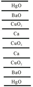 (b)
(b)
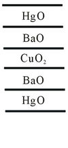
Figure 1. Layering schemes of (a) Hg-1201; (b) Hg-1223.
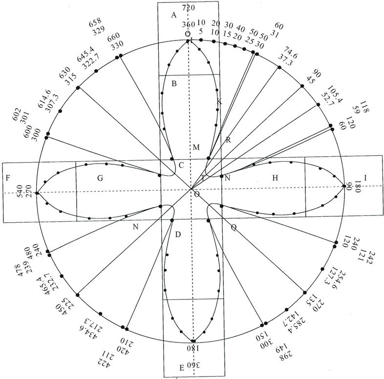
Figure 2. Model of hole-pairs in ab-plane. Both the holes traverse the same path but at any instant they are on the opposite sides of the central point. This figure is reproduction of Figure 1 from [2]. It has been reproduced to get a clearer picture of preformed hole-pairs.
It was concluded from above arguments that even in continuous (CuO)2 sheet, if a hole wandering in the (CuO)2 plane on entering a (CuO)2 unit cell will produce the same effect or resulting into ferromagnetic coupling of the spins of the holes of the 4 Cu2+ ions. It can be said that the following equation will hold good:
An isolated (CuO)4 plaquette = a (CuO)2 unit cell in the continuous CuO2 sheet + a hole inside it.
It has been reported in [12] that when a hole enters a CuO2 unit cell, the spins align vertically above the CuO2. The field produced will be equal to 4 μ/r3, where μ = magnetic moment of a hole and r = distance from the holes. Its maximum value at the center of the plaquette ≈ 1900 gauss. The [12] also suggests a relation between the direction of entry of the hole in a CuO2 plane and the direction of the magnetic field produced. The direction of the magnetic field produced remains at 90º to the direction of entry of the hole and inclined to it in clockwise direction.
1.2. 41 meV Peak Observed in Neutron Diffraction and Nuclear Magnetic Resonance
A peak at 41 meV (with a little difference in energy from one to other superconductor) is observed in neutron diffraction and nuclear magnetic resonance spectra of high temperature superconductors. This peak is associated with spin angular momentum. 41 meV when equated to hν, ν comes to be equal to 1013 hertz or time-period T = 10–13 sec. We associate this frequency with oscillations of spins of 4 Cu2+ holes, which means that they oscillate with this frequency from vertically upward direction to the vertically downward direction. The manner of oscillation is that when the spins are aligned vertically upward, they produce maximum magnetic field, then they distribute themselves in CuO2 plane in completely dephased manner producing zero magnetic field, and again they align in the vertically downward direction producing maximum magnetic field in the opposite direction. Again they come back to the CuO2 plane producing zero magnetic field and so on.
1.3. Exchange Interaction
There is always exchange interaction between two Fermions when they exist within certain separation. In the CuO2 plane when two holes come near each other from opposite sides at less than a certain distance, they are bound as a hole-pair. This pair of holes under the effect of magnetic field generated by four Cu2+ holes in the CuO2 unit cells move together in a path which is like a 3dx2–y2 electron orbital in a atom. When the separation between the holes is very small the Coulomb repulsion between the holes will supersede exchange attraction. In 3dx2–y2 path when the separation between the holes becomes large, the holes are turned back due to magnetic mirror effect. To elucidate the concept of magnetic mirror, it may be mentioned that the pole regions of the earth serve as magnetic mirrors that reflect the incoming charged particles of ionosphere and they move back and forth between two poles. The two poles of the earth act as a magnetic bottle. Mathematically also, for a charged particle moving in a magnetic field, we have mv2/r = q vxH or r = mv/qH, where m = mass of the particle, v = velocity of the particle, q = charge on the particle, r = radius of curvature and H = strength of magnetic field. The relation r = mv/qH can be written as r = v/α H, where α = q/m = specific charge, which is a constant quantity. In the 3dx2–y2 path of the holes v is constant (components vx and vy may change but not v by application of magnetic field). Hence from the relation, r = v/α H, greater is H, smaller is r. At the farthest distance between the holes in the 3dx2–y2 configuration the magnetic field is the highest and so the radius of curvature smallest. Therefore, the holes turn back from these positions. Then they face decreasing magnetic field and continue their journeys forward.
1.4. Preformed Hole-Pairs Formed at Temperatures Higher than Transition Temperature
It may be mentioned here that preformed hole pairs are formed at much higher temperatures than Tc. As the temperature is lowered their number goes on increasing. At a particular low temperature (Tc), they undergo BoseEinstein condensation resulting into superconducting state.
For better understanding of the above ideas, the Figure 1 of [2] is reproduced below as Figure 2 in the present paper to maintain the continuity of the numbering of figures. There are many similarities and also some dissimilarities with the model we are going to give for c-axis transport.
Now we will show how the preformed hole-pairs are formed in electrical conduction along c-axis of cuprate superconductors. The shape and size of the paired charge carriers (holes) are essentially derived on the same lines as in the ab-plane as given in [2], but in details they are quite different. If one walks along the ab-plane, one finds uniform landscape consisting of CuO2 unit cells only. But if one travels along the c-axis or in a direction perpendicular to ab-plane, one has to cross through different types of terrains at nearly equal intervals. For example, if one travels along c-direction inside the Tl-2212 crystal, one has to cross through the patches consisting of CuO2, Ca, CuO2, BaO, TlO, TlO, BaO, CuO2 unit cells as shown in the Figure 3(b) and repetitions of such patches. It has been reported in [13-16] that c-axis resistivity is ≈102 to 105 times larger than resistivity in ab-plane. Caxis resistivity sometimes even exceeds maximum metal resistivity of Mott-Ioffe-Regel limit. Maximum metallic resistivity is attained when mean free path of electrons = interatomic distance. Crossing this limit means that mean free path is less than interatomic distance. Though c-axis resistivity ρc is much higher than ρab in the normal state but the transition temperature Tc remains the same in ab-plane or along c-axis. The origin of very high c-axis resistivity in normal state is that c-axis transport is metallic at higher temperatures, semiconducting at lower temperatures and again metallic before Tc [16] but in abplane, it is metallic throughout upto Tc. In the superconducting state, the transport in ab-plane is through preformed hole-pairs and along c-axis also, transport between planes is through Josephson’s tunnelling of preformed hole-pairs. These two kinds of hole-pairs along c-axis and in ab-plane are different in size and shape but are Bosonic particles and do not encounter any resistance in transportation.
Kumar et al. [13-15] gave a very reasonable explanation for highly enhanced resistivity in c-axis transport in normal state. They interpreted the suppression of single particle transport along the c-axis in the normal state as blocking of the inter-block transport by the intra-block coupling to the many body environments (i.e., entanglement with other electronic degrees of freedom). This mechanism is called Quantum Zeno Effect (QZE). However as stated earlier, the Bosonic preformed hole-pairs at Tc do not suffer any scattering from the above or any other mechanism.
Now we will take up the construction, shape and size of the preformed hole-pairs in the electric transport along c-axis of cuprate superconductors that undergo BoseEinstein condensation at the transition temperature Tc, which is the main aim of this paper. Broadly, there are 5 types of high Tc cuprate superconductors: 1) La-214 (La2–x- MxCuO4, M = Ba, Sr); 2) Y-123 (YBa2Cu3O7–δ); 3) (Tl2 Ba2Can–1CunO2n+4 with n = 1, 2, 3); 4) (Bi2Sr2Can–1CunOx with n = 1, 2, 3); and 5) (HgBa2Can–1CunOy with n = 1 and 3).
The properties of the last three superconductors are more anisotropic than the first two. CuO2 is common among all of them. The layering schemes of all the superconductors have been given in the Figures 1 and 3-5. The main properties of superconductors have been given in the Table 1.
It is well known that in superconductors, CuO2 layers
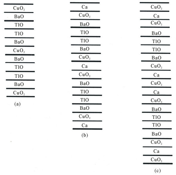
Figure 3. Layering schemes of (a) Tl- 2201, (b) Tl-2212, (c) Tl-2223. Note: Layering schemes of Bi-2201, Bi-2212 and Bi-2223 are similar to those of their Tl-counterparts with the difference that instead of Tl and Ba in Tl-superconductors, Bi and Sr are substituted in Bi-superconductors. Another important difference occurring in Bi-superconductors is that in the packing of layers along c-axis, two layers of BiO separated by 3Å are shifted relative to each other along the diagonal direction of the perovskite sub-cell.
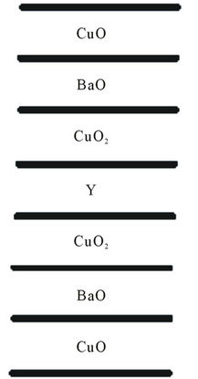
Figure 4. Layering scheme of Y-123.
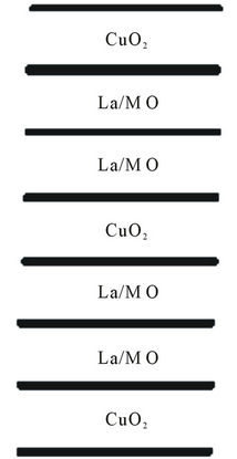
Figure 5. Layering scheme of La-214.
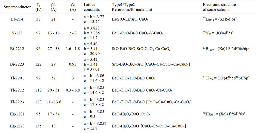
Table 1. Some important data about superconductors. 36Kr84 = 1s22s22p63s23p63d104s24p6. 54Xe131 = 1s22s22p63s23p63d104s24p6 4d105s25p6. Ox denotes partial filling.
are the seat of superconductivity and they govern most of the properties. So depending upon the number of CuO2 layers in the unit cell of a superconductor, they have been divided into three categories: 1) Having 3 layers of CuO2 as in Tl2Ba2Ca2Cu3Ox, Bi2Sr2Ca2Cu3Oy, HgBa2Ca2Cu3Oz; 2) 2 layers of CuO2 as in Tl2Ba2CaCu2Ox, Bi2Sr2CaCu2Oy, YBa2Cu3O7–δ; 3) 1 layer of CuO2 as in Tl2Ba2CuOx, HgBa2CuOz, La1–xMxCuO4 (where M = Ba or Sr).
Before going further with the discussion of hole-pair formation, we will establish clear distinction between two kinds of holes which have been mentioned earlier in the text and will often come in our discussion to avoid any confusion. One kind of hole is that which is generated in the superconductors due to the level of doping and which is the electric current carrier in superconductors and it will be called lattice hole. The other kind of holes is that which is associated with Cu2+ ions in CuO2 network and which generates magnetic field on arrival of a lattice hole in the CuO2 unit cell. This kind of holes will be called Cu2+ holes.
First we discuss the representative case of Tl2Ba2CaCu2Ox, in the category (2) consisting of 2 layers of CuO2. In all our discussions, we will be mainly interested in giving the shape, size and symmetry of the preformed hole-pairs (i.e., order parameter) in transport along c-axis and estimating the value of ξc (coherence length along c-axis). In Tl-2212, there are two CuO2 layers or blocks and in between them there is one layer containing Ca as shown in the Figure 3(b) [Layer is the common term but it is generally used for 2-dimensional objects. Along the c-axis, there are 3-dimensional blocks of TlO, BaO, CuO2 etc. heaped one over the other. So in our discussion, both the terms can be used as synonyms]. As CuO2 layers are most active layers, therefore, the hole pair is expected to be formed in between these two layers or in the block containing Ca.
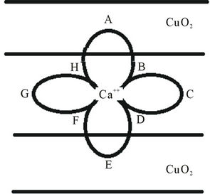
We now explain the formation of hole-pairs shown in the Figure 6(a). The coordinate system for the Figure 6 has been given in the Figure 6(c).
There are two lattice holes, one approaching from above and the other from below. Only the motion of the hole 1 starting from position A in the figure will be described. Same kind of description is true for the hole 2 starting from E in the figure. The hole 2 is always situated diagrammatically opposite to the hole 1 because of starting from the opposite side. The motion of the two holes is guided by the three effects mentioned in the beginning, 1) magnetic field generated by the advent of a hole inside a CuO2 block; 2) oscillations of spins of holes of four Cu2+ ions with a frequency of 1013 hertz which produce varying magnetic field with the same frequency. Figure 6(b) shows the variation of magnetic field from a maximum to zero, then from zero to the maximum but in opposite direction and then again to zero as shown in Parts A, B, C, D respectively; 3) Both the holes are always under the effect of exchange interaction which varies with separation between the holes.
It needs to be mentioned here that the motion of a charged hole in a magnetic field is governed by right hand rule. Hole 1 starting from A travels with its thermal velocity towards the Ca-block but not in straight line but along the curved path AB (Figure 6(a)) due to the magnetic field direction shown in the Figure 6(b)(A). Then it is deflected along the path BC due to Coulomb repulsion from Ca2+ ion and also from the hole 2 which has simultaneously reached near the Ca2+ ion at F on the opposite side of hole1. At this instant the magnetic field seems to have nearly vanished (Figure 6(b)(B)) and the Coulomb repulsion seems to have superseded attractive exchange interaction. Charge distribution on the Ca2+ ion seems to act as reflecting planes for holes 1 and 2 when they reached the positions at B and F respectively. From B, the hole 1 reaches C under the effect of increasing magnetic field in the downward direction. From C the hole 1 reverses its direction of motion and follows the path C to
 (a)
(a)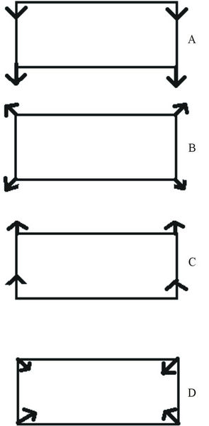 (b)
(b)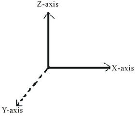 (c)
(c)
Figure 6. (a) Model of hole-pairs in c-axis transport; (b) Directions of magnetic field produced by spin alignments of 4 Cu2+ ions of CuO2 unit cell. From A to B to C to D to A again, the spin arrangements have been shown at intervals of T/4. Time-period of spin oscillation (T) = 10–13 sec; (c) Coordinate system for all figures under Figure 6.
D. At C the magnetic field is maximum but vertically downward and at D, the magnetic field becomes nearly zero. The important question is how the path of the hole 1 is reversed? The reason is the magnetic mirror effect. Magnetic mirror effect has been explained earlier. At D, again the Coulomb repulsion supersedes exchange interaction and charge distribution on Ca2+ acts like a reflecting plane and directs hole 1 towards E. From D, the hole 1 reaches E under the effect of magnetic field increasing vertically upwards. In the time the hole 1 has reached E through the path ABCDE, the hole 2 has reached A through the path EFGHA. The hole 2 experiences same kind of forces as the hole 1. Both the holes are always situated diametrically opposite to each other in the path ABCDEFGHA. The two holes continue moving along the path ABCDEFGHA and form a hole-pair.
In the journey of hole 1 from A, there are 4 stations at B, C, D and at E. At each station, there is drastic change in the path of the hole 1. The question is what is special about these stations? As have been mentioned above, these are the positions from where magnetic field changes from maximum at A to minimum or zero at B, then maximum at C but in the opposite direction, then zero at D and again maximum at E in the same direction as at A. In the journey of lattice hole from A to E, the spins of Cu2+ holes have completed one full oscillation. It means that time taken by the hole 1 is 10–13sec. as the frequency of oscillations of spins of Cu2+ holes which cause magnetic field = 1013 hertz. Therefore, the time for the hole 1 to complete each segment of its journey A to B; B to C ; C to D and D to E should be the same and equals to 1/4 × 10–13 sec. For completing each segment of its journey, it travels with its thermal velocity and for equal time of 1/4 × 10–13 sec. Hence all the segments should also be of the same length. The same is true for the hole 2. Thus it can be said that in coming from A to E, spins have completed one oscillation or tilted by 360˚, though the change of geometrical angle =180˚ only as seen from the Figure 6(a) and also Figure 2.
The shape of the hole-pair shown in the Figure 6(a) is 3dz2–x2 because the coordinates involved are z-axis and x-axis. It is not of usual 3dx2–y2 type obtained for the hole pair in ab-plane of superconductors. The dimensions of 3dx2–y2 hole pairs in ab plane is usually a few tens of Angstroms. But along c-axis, the dimensions are usually less than aand b-lattice constants. The reason for the small dimension of hole-pairs along c-axis transport may be explained as follows. We have seen that the length of every limb of every 3dz2–x2 hole pair is decided by the distance travelled by a hole in time = 1/4 × 10–13 sec. or equals to velocity of the hole x1/4 × 10–13 sec. Because of incoherent in-plane scattering [13-15], the velocity of hole in the x-direction is much reduced. Also the velocity of the hole in the z-direction or along the c-axis is also much reduced due to uneven terrain and also due to the Quantum Zeno Effect (QZE) [13-15] which suppresses c-axis transport due to intra-block incoherent scattering. It may be possible that limbs of hole-pairs in zand x-directions may be of different length depending upon the resistivity along the zand x-directions. It is well known that greater is the resistivity of a material, less is the velocity of charge carriers. Because the velocities of holes along xor z-direction are not known exactly, it can not be said which limb is bigger and which shorter. But it is known that both limbs will be constrained in comparison to 3dx2–y2 hole-pairs in ab-plane.
Now we discuss Tl2Ba2Ca2Cu3Ox (others in the class being Bi2Sr2Ca2Cu3Oy and HgBa2Ca2Cu3Oz) which has three bocks of CuO2 and two intervening blocks of Ca as shown in the Figure 3(c). In this case there are two pairs of CuO2 layers each containing a Ca layer in between. One pair consists of upper and middle CuO2 layer with a Ca layer in between, the other pair consists of the middle and the lower CuO2 layer with another Ca layer in between. Two holes coming from opposite sides, one appearing in the upper CuO2 layer and the other appearing in the middle layer simultaneously will form a hole-pair in the intervening Ca block in the same manner as explained in the case of Tl-2212 discussed above. In the other pair of CuO2 layers consisting of the middle and the lower CuO2 blocks with a Ca block in between, a hole-pair will be formed in the same way as in the first pair. Definitely, there is more probability of hole-pairs in Tl-2223 than in Tl-2212, which should ensure higher Tc for Tl-2223 than for Tl-2212, which is corroborated by experiment. Tc of Tl-2223 = 128 K and Tc for Tl-2212 = 118 K.
Next we discuss Tl2Ba2CuOx (or Tl-2201). Others in this class are HgBa2CuOz and La2–xMxCuO4, where M = Ba or Sr. In this system , there is only one CuO2 layer bounded on both sides by four blocks of BaO, TlO, TlO, BaO as shown in the Figure 3(a). If two holes, one from above and one from below reach the CuO2 block simultaneously, both will induce the spins of four Cu2+ holes in the CuO2 unit to align in the A-configuration [12] of the Figure 6(b). and then oscillate from one configuration to the other (i.e., A to B to C to D to A). In the same way as in Tl-2212, the two holes under the action of the magnetic field produced from the fluctuating spins of the four Cu2+ ions and exchange effects will follow a closed path in the plane of the CuO2 layer, i.e., in the ab-plane or xy-plane. The symmetry of the order parameter will be of 3dx2–y2 and not 3dz2–x2 as in Tl-2212. The hole-pairs along c-axis transport in other cases discussed here have been found to be of 3dz2–x2 type but in the case of Tl-2201 and its associates, it is of type 3dx2–y2. It has been found experimentally that transport in Tl-2201 is metallic both in ab-plane and along c-axis. There arises an obvious question. If in Tl-2201, the order-parameter both in ab-plane and along c-axis is of 3d x2-y2 type and transport in both case being metallic, why there should be so much difference between ξab (= 52 Å) and ξc (= 3 Å). It should be because of different paths taken in current flow in ab-plane and along c-axis. Conduction in the ab-plane is smooth consisting of homogeneous CuO2 unit cells, but conduction along c-axis is through heterogeneous slabs of BaO, TlO, TlO, BaO and their repetitions. Moreover, Quantum Zeno Effect (QZE) discussed earlier will be effective in reducing the velocity of hole in x-direction due to incoherent scattering.
From the Table 1, it is noticed that ξab are of the order of tens of Angstroms, but ξc is less that aand b-lattice constants except in Tl-2212, where it has been reported to vary from 0.3 to 6.8 Å. Such large variation of ξc seems to be due to some kind of experimental error. In [13-18], it has been pointed out that it is quite possible for any measurement of resistivity ρc to pick up some in-plane component of resistive tensor—perhaps externally due to misalignment of contacts or internally due to the randomly distributed defects.
There are two more points worth considering: 1) Why Tc of a superconductor increases when number of CuO2 layers per unit cell increases (see Table 1) from one to three. It is because more the number of CuO2 layers, greater will be the number of hole-pairs formed and transition temperature will be reached at higher temperature. Legget [19] has shown that for identically doped members of the same homologous series, as a result of the inter-plane Coulomb interaction, the difference ∆Tc(n) of the transition temperature for the nth member from the single layer value is given by ∆Tc(n) = Constant (1 – 1/n). This value of ∆Tc(n) is to be added to the single layer Tc.
Ratan Lal et al., [20] on the basis of phenomenological arguments and structural features have inferred that Cu 3d3z2-r2 orbitals are involved in the transport along c-axis. This kind of orbital may be correct for single particle transport in normal state. But the question with which we are concerned here is to find out what is the symmetry of the hole-pair in the electrical transport along c-axis at Tc and below. It has been found out here that symmetry of the hole-pair carrying current along c-axis at Tc or below is of 3dz2–x2 type for n (number of CuO2 layers/unit cell) =2 and 3 and of 3dx2–y2 type for n = 1.
2. Summary
The model of preformed hole-pairs in ab-plane of cuprate superconductors has been proposed earlier, which is of symmetry 3dx2–y2. The model of hole-pairs in the electrical transport along c-axis at Tc and below has been proposed in this paper. The models for c-axis transport have been proposed in three sections corresponding to the number of layers n = 1, 2, 3 per formula unit. For n = 2 and 3, the symmetry of the preformed pairs is of 3dz2–x2 type (i.e., in zx-plane). But for n = 1, the symmetry of the order parameter is of 3dx2–y2 type. The reasons leading to very small coherence length in c-axis transport have been given. It is suggested to carry out angle-dependent experimental studies on cuprate superconductor single crystals as thermal conductivity, specific heat, STM imaging etc to verify the proposed hole-pair models.
REFERENCES
- R. J. Singh, “Preformed Hole Pairs in Cuprate Superconductors,” International Journal of Modern Physics B, Vol. 23, No. 1, 2009, pp. 53-76.
- R. J. Singh, “Model of Preformed Hole-Pairs in Cuprate Superconductors,” Journal of Modern Physics, Vol. 2, No. 8, 2011, pp. 53-76.
- A. Punnoose, B. P. Maurya, J. Mathew, M. Umar, M. I. Haque and R. J. Singh, “EPR Observation of Cu2+-Cu2+ Pairs in Cupric Oxide Powders,” Solid State Communications, Vol. 88, No. 3, 1993, pp. 195-198.
- R. J. Singh, A. Punnoose, J. Mathew, B. P. Maurya, et al., “S = 1 and S = 2 EPR Signals in Modified CuO and BaCuO2,” Physical Review B, Vol. 49, No. 2, 1994, pp. 1346-1349. doi:10.1103/PhysRevB.49.1346
- R. J. Singh, M. Ikram, A. Punnoose, B. P. Maurya and S. Khan, “Copper Tetramers in High-Temperature Superconductors,” Physics Letters A, Vol. 208, No. 4, 1995, pp. 369-374.
- A. Punnoose and R. J. Singh, “EPR Studies of High-Tc Superconductors and Related Systems,” International Journal of Modern Physics, Vol. 9, No. 10, 1995, pp. 1123-1157. doi:10.1142/S0217979295000471
- S. Khan, M. Ikram, A. Singh and R. J. Singh, “EPR Study of Deoxygenated La2CuO4,” Physica C, Vol. 281, No. 2-3, 1997, pp. 143-148. doi:10.1016/S0921-4534(97)00328-6
- S. Khan, A. Singh and R. J. Singh, “EPR Study of La2−xSrxCuO4 [M = Ba,Sr],” Solid State Communications, Vol. 106, No. 9, 1998, pp. 621-626.
- S. Khan, A. Singh and R. J. Singh, “EPR Study of La1.854Sr0.146CuO4,” Physica C, Vol. 325, 1999, pp. 165-172. doi:10.1016/S0921-4534(99)00513-4
- R. J. Singh, P. K. Sharma, A. Singh and S. Khan, “EPR Spectra of Deoxygenated High Temperature Superconductors,” Physica C, Vol. 356, No. 4, 2001, pp. 285-296. doi:10.1016/S0921-4534(01)00283-0
- Q. B. Meng, Z. J. Wu and S. Y. Zhang, “Evaluation of the Energy Barrier Distribution in Many-Particle Systems Using the Path Integral Approach,” Journal of Physics: Condensed Matter, Vol. 10, No. 5, 1998, pp. L85-L88.
- P. C. Dai, H. A. Mook, G. Aeppli, S. M. Hayden and F. Dogan, “Resonance as a Measure of Pairing Correlations in the High-Tc Superconductor YBa2Cu3O6.6,” Nature, Vol. 406, No. 6799, 2000, pp. 965-968. doi:10.1038/35023094
- N. Kumar, T. P. Pareek and A. M. Jayannavar, “Normal State c-Axis Resistivity of the High-Tc Cuprate Superconductors,” 1997.
- N. Kumar, “The Zeno Effect and Interlayer Pairing Mechanism for High Temperature Superconductivity in Layered Materials,” 2000.
- N. Kumar and A. M. Jayannavar, “Temperature Dependence of the c-Axis Resistivity of High-Tc Layered Oxides,” Physical Review B, Vol. 45, No. 9, 1992, pp. 5001- 5004.
- K. Takenaka, M. Mizuhasi, H. Takagi and S. Uchida, “Interplane Charge Transport in YBa2Cu3O7−y,” Physical Review B, Vol. 50, No. 9, 1994, pp. 6534-6537.
- Y. C. Ma, J. W. Liu, H. W. Lu and H. L. Zheng, “Out of Plane Temperature Dependent Resistivity Studies on TlBased Superconductors,” Journal of Physics: Condensed Matter, Vol. 19, No. 18, 2007, pp. 186203-186209. doi:10.1088/0953-8984/19/18/186203
- R. Jin, D. P. Grandatto and H. R. Rott, “Normal State Resistivity of Superconducting Bi1.95Sr1.65La0.4CuO6+δ,” Physica C, Vol. 250, No. 3, 1995, pp. 395-402. doi:10.1016/0921-4534(95)00369-X
- A. J. Legget, “Cuprate Superconductivity: Dependence of Tc on the c-Axis Layering Structure,” Physical Review Letters, Vol. 83, No. 2, 1999, pp. 392-395. doi:10.1103/PhysRevLett.83.392
- R. Lal, Ajay, R. L. Hotta and S. K. Joshi, “Model for c-Axis Resistivity in Cuprate Superconductors,” Physical Review B, Vol. 75, No. 10, 1998, pp. 6126-6136.