Journal of Signal and Information Processing
Vol. 4 No. 2 (2013) , Article ID: 31000 , 12 pages DOI:10.4236/jsip.2013.42023
Secured Transmission of ECG Signals: Numerical and Electronic Simulations
![]()
Laboratoire d’Electronique et de Traitement du Signal, GRETMAT, National Advanced School of Engineering, University of Yaoundé I, Yaoundé, Cameroon.
Email: kenfackwamba@yahoo.com, alain_tiedeu@yahoo.fr
Copyright © 2013 Gutenbert Kenfack, Alain Tiedeu. This is an open access article distributed under the Creative Commons Attribution License, which permits unrestricted use, distribution, and reproduction in any medium, provided the original work is properly cited.
Received March 20th, 2013; revised April 21st, 2013; accepted April 29th, 2013
Keywords: Chaos; Demultiplexer; Decryption; Electrocardiogram (ECG); Encryption; Multiplexer; Secure Communications
ABSTRACT
In many domains of science and technology, as the need for secured transmission of information has grown over the years, a variety of methods have been studied and devised to achieve this goal. In this paper, we present an information securing method using chaos encryption. Our proposal uses only one chaotic oscillator both for signal encryption and decryption, for avoiding the delicate synchronisation step. We carried out numerical and electronic simulations of the proposed circuit using electrocardiographic signals as input. Results obtained from both simulations were compared and exhibited a good agreement proving the suitability of our system for signal encryption and decryption.
1. Introduction
During the last decades, the demand for cryptographic techniques to secure transmitted information has increased. For multiple reasons, the need to protect information arises. A number of attempts have been carried-out in research. Basically, the literature proposes two main approaches of information encryption. The first is done through algorithms of encoding and decoding implemented in software. Several techniques were used to encrypt data streams, but interception was possible in case of the encryption key hacking. Authors therefore massively turned to the circuit-based approach. A particular class that has received much attention in research these last years is chaos-based techniques. The idea of using chaotic signals to transmit secured information appeared at the beginning of 90’s after it had been proved by Peccora and Carroll that the chaotic system can be synchronized [1-3]. The robustness in multipath environments, resistance to jamming, and low probability of interception are essential when dealing in communication systems. Properties like sensitivity to initial conditions, random-like behaviour, nonlinear dynamics found in chaotic oscillators are an advantage to fight against interception. The principle of these techniques is to use oscillators that generate chaos to modulate the information signal that has to be transmitted. After reception, the signal is demodulated and the secret information recovered.
Some authors concentrated on designing different oscillators for chaos generation. For example, chaotic behaviours of Duffing, Chua, Colpitts and Van der Pol oscillators [4-9], just to name a few, have been studied.
A second group of authors was preoccupied by synchronization of chaotic oscillators involved in the emission and reception parts, using a variety of techniques [1-4,10-16]. Some of these had secured communications as one of the applications.
Mindful of the fact that synchronisation is very sensitive to noise, some authors have tried a number of techniques excluding any need for synchronisation. The first of this type is chaos shift keying (CSK) [17,18]. CSK is a method of digital modulation. Depending on the current value of the N-ary message symbol, the signal xi(t) (i = 1, ∙∙∙N) from one of N chaos generators with different characteristics is transmitted. The main drawback of the CSK is that the threshold level required by the decision circuit depends on the signal to noise ratio (SNR). A special case of CSK is the chaotic on-off keying (COOK) [19]. COOK uses one chaotic oscillator, which is switched on or off according to a binary message symbol to be transmitted. The major disadvantage of the CSK system, namely that the threshold value of the decision circuit depends on the noise level, also appears in COOK. This means that by using COOK it is possible to maximize the distance between the elements of the signal set, but the threshold level required by the decision circuit depends on the SNR.
However, the threshold value can be kept constant and the distance can be doubled by applying the differential CSK (DCSK) [20,21]. In DCSK, the two channels are formed by time division. For every message symbol, the reference signal is first transmitted, followed by the modulated reference carrying the message symbol. The principal drawback of DCSK arises from the fact that every information bit is transmitted by two sample functions because the bit rate is halved.
This problem can be avoided using frequency modulation DCSK (FM-DCSK) [22,23], where the transmitted energy per bit belonging to one symbol, is kept constant. Here, as in the DCSK technique, every information bit is transmitted by two sample functions, where the first part serves as a reference, while the second part carries the information. The operation of the modulator is the same as in DCSK, the only difference is that not the chaotic, but the FM modulated signal is the input of the DCSK modulator. The limitation of standard FM-DCSK system is the fact that only one information-bearing is transmitted after the reference signal.
Several different methods have been proposed in the literature to increase the data rate of DCSK, of which one of the most efficient is the quadratic chaos shift keying (QCSK) [24,25] scheme. The basic idea underlying the QCSK scheme is the generation of chaotic signals which are orthogonal over a specified time interval. This allows the creation of a basis of chaotic functions from which arbitrary constellations of chaotic signals can be constructed. For instance, in QCSK, a linear combination of two chaotic basis functions is used to encode four symbols. The key point for exploiting this idea in a communication system is that one must be able to generate the chaotic basis functions starting from a single chaotic signal. The same concept holds for conventional digital communication schemes such as QPSK, where the quadrature component can be obtained from the phase one by means of a simple phase shifter. The main drawback of this method is its high complexity.
Among several systems proposed, one of the best performances has been achieved by the differential chaos shift keying (DCSK) scheme and its variation utilizing frequency modulation, which is FM-DCSK. This is the reason why, our method draws its inspiration from this technique.
In this paper, we suggest a very simple encryptionand-decryption system organized around a multiplexer and demultiplexer and based on the DCSK philosophy. Apart from its great simplicity, our system provides, as will be seen later a good signal to noise ratio. Finally, unlike in many of the aforementioned systems where the decrypted signal is obtained by estimation, in our proposal the final signal is actually deducted from the sent signal.
In the next section, we describe and model the circuits used in our system. This is followed in Section 3 by results obtained during our simulations. These results are discussed in Section 3. The conclusion of the paper is the object of Section 4.
2. Circuit Description and Modelling
The general diagram of the secured transmission system is given in Figure 1.
We shall now briefly describe the different elements of the system and their functioning.
2.1. Basics of Signal Encryption by Chaos
There are basically two classes of signal encryption with chaos. In the first class of systems, which is generally more complicated, the information to be hidden is injected in the system producing the chaotic signal. This approach has the disadvantage of imposing the modification of the decoding system and is more suitable when the signal to be coded is of high amplitude. The second class of systems would allow generation of the chaos which is then added to or multiply by the signal to be hidden. This technique, which is simpler in its design is appropriate for low amplitude signals like ECG and would not need the modification of the receiving system.
The central element of the encrypting bloc is the chaos generator which, in our case, is a colpitts oscillator. Let’s describe the model of the chaotic oscillator used.
2.2. Colpitts Oscillator and Circuit Equations
The Colpitts oscillator is one of the most researched and easiest oscillators. Figure 2 gives its representation. It is made of an LC oscillator, a capacitor-based voltage divider and an amplifier. The resonant circuit has three elements, namely: the inductor L and the capacitor C1 and C2. The non linear component of the circuit is the Bipolar Junction Transistor (BJT) Q2N2222.

Figure 1. Bloc diagram of the secured transmission system (STS).
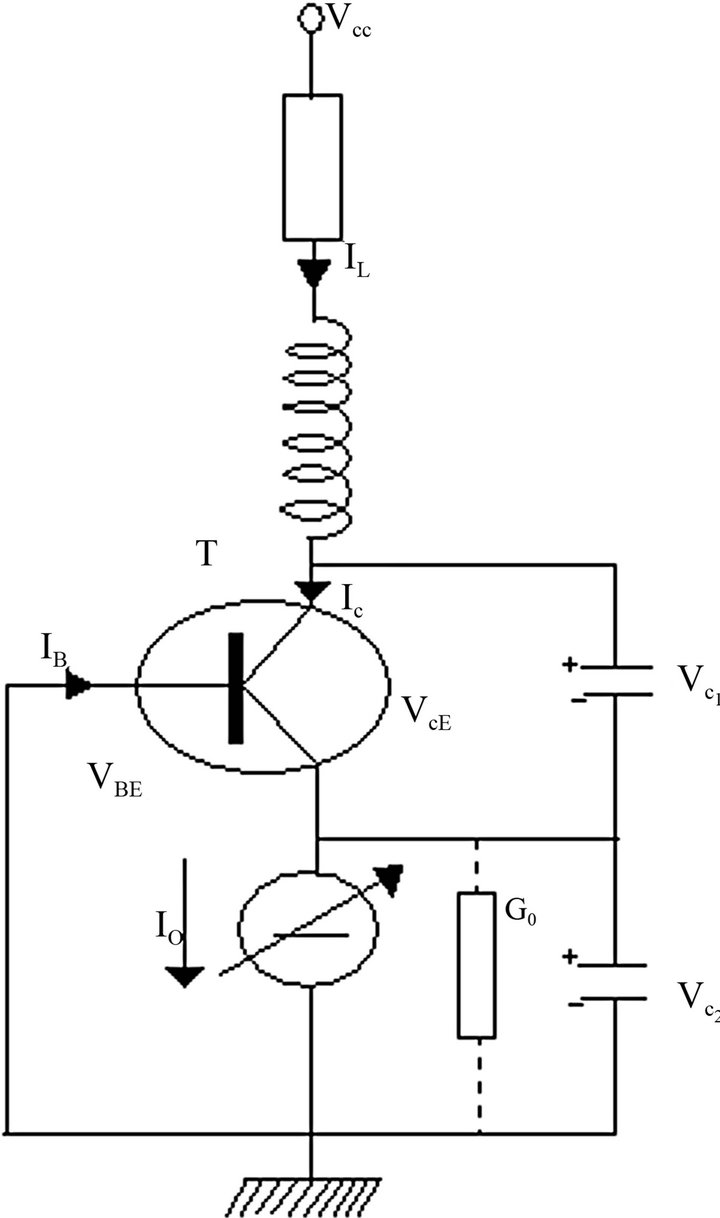
Figure 2. The colpitts oscillator.
The current source , of conductance
  polarizes the BJT. Applying Barkhausen criterium to this oscillator, the resonance frequency
  can be computed
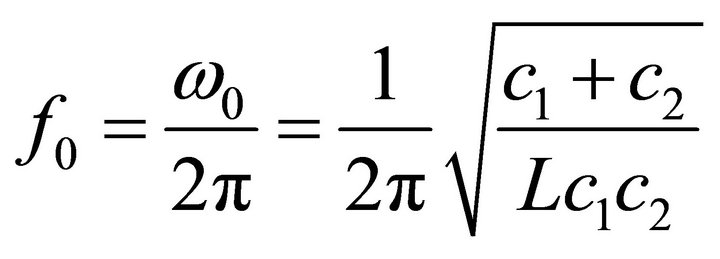 (1)
(1)
Applying Kirchhoff current and voltage laws to the circuit, we have:
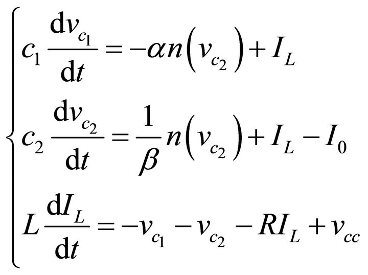 (2)
(2)
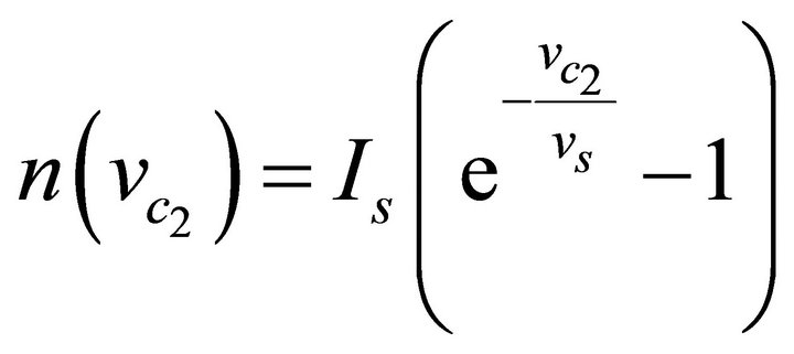
where ![]() and
and  are the BJT parameters:
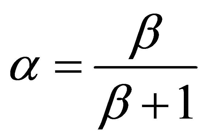 ,
, 
Let’s introduce some dimensionless variables for convenient numerical analysis:
 (3)
(3)
If  serves as control variable for the system, and posing
 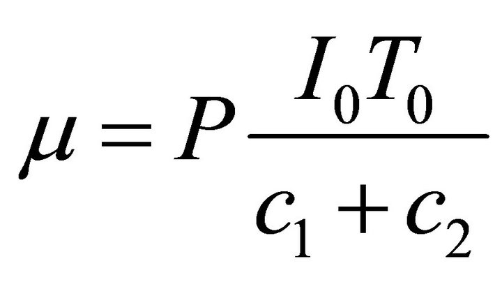 the set of Equations (2) becomes:
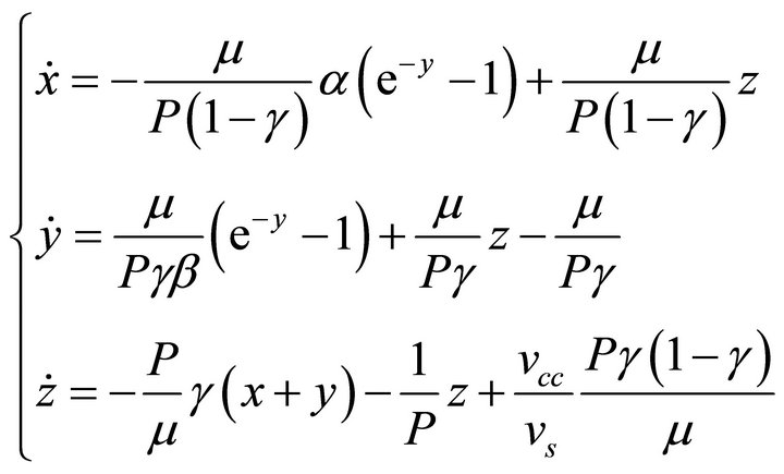 (4)
(4)
where the dot denotes the differentiation.
Changing origins, (4) becomes:
 (5)
(5)
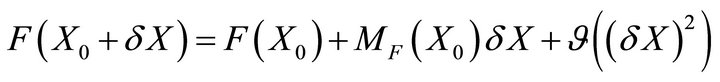
In order to study stability around the equilibrium point, let’s rewrite the system above using the formalism  where X is a three-dimensional vector and F, a function of X and of time. Performing a first order development in equilibrium point’s
  neighbourhood by means of the Jacobian matrix MF, we can have an approximation of the system dynamics when subjected to a perturbation
  where
where 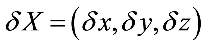
with  (6)
(6)
Therefore,  (7)
(7)
The characteristic equation of the Jacobian matrix about the equilibrium is:
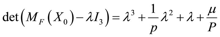 given that
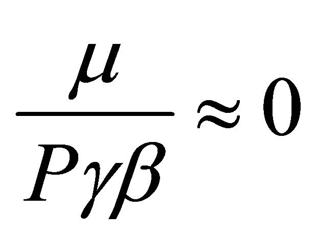 (8)
(8)
In the triplet 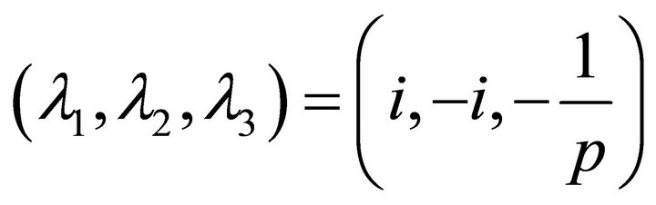 of eigenvaluesthe first two lead to oscillations while the last pulls the system towards equilibrium. The bifurcation diagram is given in Figure 3. The bifurcation diagram is a plot of the maximum value (Max) of the dimensionless variable
 (Equation (3)) as a function of μ. It can be noticed that for:
-  the system tends to stabilize around a single frequency value;
-  the system oscillates between two frequency values;
- from  many bifurcations points appear and the system exhibits a chaotic behaviour.
A usual test for chaos is calculation of Lyapunov exponents. It is common to refer to the largest one as the Maximal Lyapunov exponent (MLE), because it determines a notion of predictability for a dynamical system. The Lyapunov exponents give the average exponential rates of divergence or convergence of nearby orbits in the phasespace.
In systems exhibiting exponential orbital divergence, small differences in initial conditions which we may not be able to resolve get magnified rapidly leading to loss of predictability. Such systems are chaotic. In Figure 4 is plotted the dynamic of Lyapunov exponents for the colpitts oscillator used. For initial conditions (x = 0.2, y = 0.5, z = 0.5), the system being solved by means of 4th order Runge Kutta technique, with Step 0.01, three values of Lyapunov exponents (Lamda 1, Lamda 2, Lamda 3) are obtained:  (positive value), Lamda 2 = 0.0, Lamda 3 = −0.70 (negative value). These results validate the bifurcation diagram of Figure 3 and prove the chaotic nature of the oscillator.
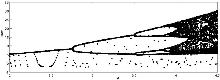
Figure 3. Bifurcation diagram of the system.
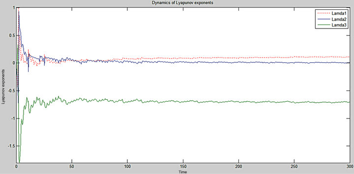
Figure 4. Dynamic of Lyapunov exponents.
2.3. Description of Encryption and Decryption Techniques
The chaotic signal studied above is used to encrypt the ECG signal. Encryption and decryption techniques which are described below are depicted in Figure 5.
The informative signal (ECG) is added to the chaotic signal. The output of the adder, which is the encrypted signal, is multiplexed with the same chaotic signal and yields Signal C. The latter is transmitted to the receiver through a physical link (copper wire in our case). At the receiver end, decryption is obtained by first of all demultiplexing Signal C and then subtracting the two output of the demultiplexer. A low pass filter is added at the output of the subtractor to discard noise from the decrypted signal.
2.4. Circuit Implementation
The different functional units of our system are indicated in Figure 6. The 2N2222 transistor is used to build the colpitts oscillator that generates the chaotic signal. This component is a common NPN bipolar junction transistor used for general purpose low-power amplifying or switching applications. It is designed for low to medium current, low power, medium voltage, and can operate at moderately high speeds. These features explain why it was chosen in this work. The adder and the subtractor were built using a classical TL082 Operational Amplifier. It is a high speed J-FET input dual operational amplifier incorporating well matched, high voltage J-FET and bipolar transistors in a monolithe integrated circuit. The device features high slew rates, low input bias and offset currents. The MUX/DMUX that appears in the system is the ADG659YCPZ integrated circuit.
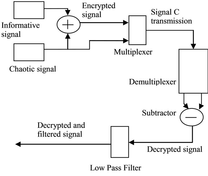
Figure 5. Encryption and decryption schemes.

Figure 6. The circuit implemented.
3. Simulation Results
3.1. Signal Waveforms
The overall circuit was built according to the scheme shown in Figure 6. The simulations were carried-out using MULTISIM which is an electronic circuit simulator. This section is dedicated to results yielded by our system. We inserted side by side results obtained from numerical (using MATLAB) and electronic (using MULTISIM) simulations.
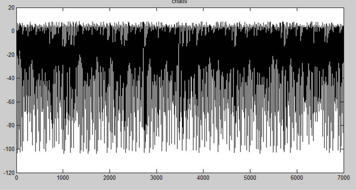
C1 and C2 are the two capacitors found on the colpitts oscillator (Figure 2). In Figure 7, the value of the voltage across C1 and C2 were plotted as a function of time. One can easily notice that both from Matlab (a, c) and Multisim (b, d) simulations, the waveforms obtained are chaotic.
Using the value  the system (5) was solved numerically using Matlab by means of fourth-order Runge-Kutta algorithm and yielded the phase portrait of Figure 8(a). On the other hand, plotting the voltage
 (a)
(a)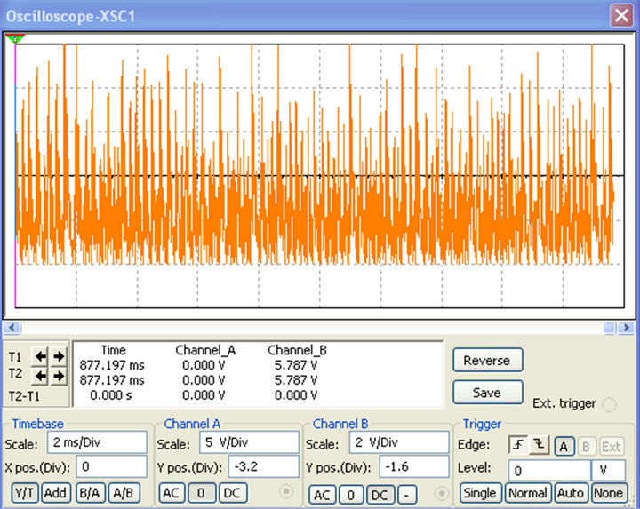 (b)
(b) (c)
(c) (d)
(d)
Figure 7. Chaotic signals from C1 and C2 from numerical (a, c) and electronic (b, d) simulations.
across C1 as a function of the voltage across C2 under Multisim, the phase portrait of Figure 8(b) was obtained. We can notice the resemblance between the two phase portraits of Figure 8.
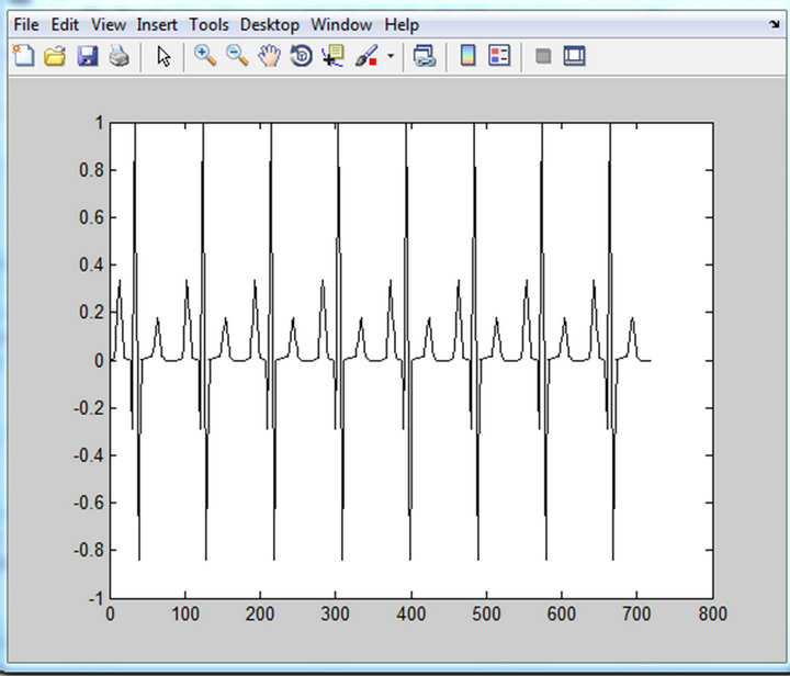
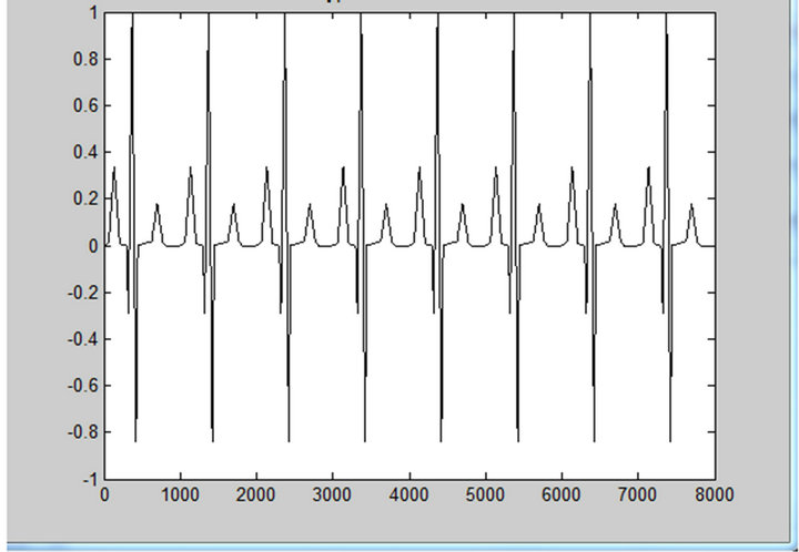
Figure 9 shows the original input ECG signal used in our simulations while the encrypted signal is plotted in Figure 10. Observing Figure 10, we can notice that the ECG signal which was clearly identifiable in Figure 9, can no more be seen. It has been hidden by our encryption system. After decryption, we obtained the waveforms in Figure 11. Both from the numerical and electronic simulations results, the form of the ECG signal can be recognized.
3.2. Decrypted ECG Signal Analysis
The decrypted ECG signal (Figure 11) yielded by our system was analyzed and compared to the initial signal in terms of mean frequency distortion (MFD) and signal to noise ratio (SNR). The mean frequency (MF) is given below:
 (9)
(9)
where  is the spectral power density of the ECG signal.
 (10)
(10)
The MFD is a very important metric that indicates how much the reconstructed signal has shifted from the originnal one, frequency-wise. For each frequency of the initial ECG signal, we obtained a frequency for the reconstructed signal. The MFD is then computed. This work was carried out for ECG signal frequencies ranging from 25 Hz to 100 Hz. The mean value of the different MFDs obtained was calculated and we obtained .This
.This
 (a)
(a)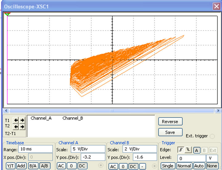 (b)
(b)
Figure 8. Phase portraits simulated with MATLAB (a) and MULTISIM (b).
 (a)
(a)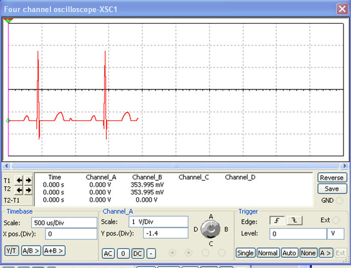 (b)
(b)
Figure 9. Original ECG signal in MATLAB (a) and MULTISIM (b) respectively.
very low value proves that the signal frequency is conserved. The SNR used here is given by:
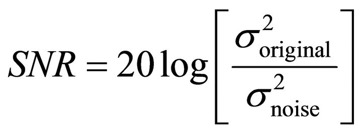 (11)
(11)
where  is the original signal’s power and
  that of the noise. The noise is defined as follows:
 (12)
(12)
where  is the original ECG signal while
is the reconstructed or decrypted ECG signal.
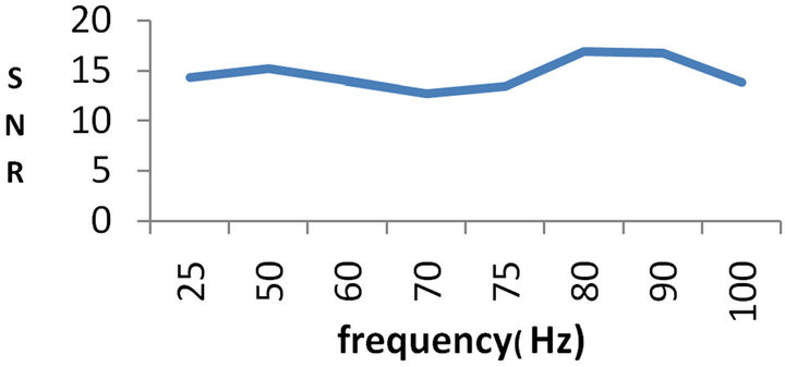
Figure 12 gives the evolution of the SNR as the frequency of the original signal varies from 25 Hz to 100 Hz.
As can be seen on the plots, the SNR is always greater than 10. It reaches its maximal value for a frequency of 80 Hz. We evaluated the SNR from 25 to 100 Hz. This upper value was chosen because we targeted signals of frequency lower than 100 Hz which is what medical doctors use for diagnosis. The minimal value of the SNR may be explained by the fact that the different parasite
 (a)
(a)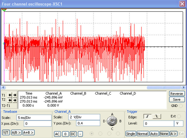 (b)
(b)
Figure 10. Encrypted ECG signal in MATLAB (a) and MULTISIM (b).
elements in the system are arranged in such a way that they build up a rejection filter centered on the frequency 75 Hz. This deserves a more careful study that we shall carry out in future works. We have a relatively high SNR as can be seen in Figure 12. This is an asset for our system. It can be explained by the fact that in our case, the real signal is transmitted whereas in works in the literature [17-25], the reconstructed signal is computed through an estimation. It is also obvious that our system using analog circuits, will surely be faster than those of the works mentioned above. Finally, it is worth noting that the proposed system uses very basic and simple electronic circuits (MUX and DMUX) to carry out the job while conserving the original signal frequency.
4. Conclusion
We have developed and proposed a very simple system for secured transmission of ECG signals. It can be noted that the original signal is recovered almost without frequency distortion and with a good SNR. There is a good agreement between the numerical and electronic simulations results. In future works, we plan amongst other
 (a)
(a)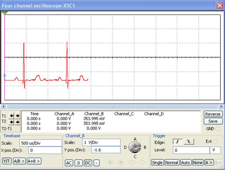 (b)
(b)
Figure 11. Decrypted ECG signal from MATLAB (a) and MULTISIM (b).
 (a)
(a)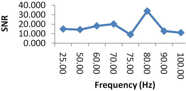 (b)
(b)
Figure 12. SNR plots in MATLAB (a) and MULTISIM (b).
things, to implement the system developed and get experimental results and to take into account non-linear perturbations in the transmission line.
REFERENCES
- L. M. Pecora and T. L. Carroll, “Synchronization in Chaotic Systems,” Physical Review Letters, Vol. 64, No. 8, 1990, pp. 821-824. doi:10.1103/PhysRevLett.64.821
- T. L. Carroll and L. M. Pecora, “Synchronizating Chaotic Circuits,” IEEE Transactions on Circuits and Systems, Vol. 38, No. 4, 1991, pp. 453-456. doi:10.1109/31.75404
- L. M. Pecora and T. L. Carroll, “Synchronized Chaotic Signal and Systems,” Proceedings of Conference on Acoustics, Speech and Signal Processing, San Francisco, 23-26 March 1992, pp. 137-140.
- J. Kengne, J. C. Chedjou, G. Kenne, K. Kyamakya and G. H. Kom, “Analog Circuit Implementation and Synchronization of a System Consisting of a Van Der Pol Oscillator Linearly Coupled to a Duffing Oscillator,” Nonlinear Dynamics, Vol. 70, No. 3, 2012, pp. 2163-2173. doi:10.1007/s11071-012-0607-8
- A. Elwalkil and M. Kennedy, “Improved Implementation of Chua’s Chaotic Oscillator Using Current Feedback Op Amp,” IEEE Transactions on Circuits and Systems, Vol. 47, No. 1, 2000, pp. 76-79. doi:10.1109/81.817395
- J. Kengne, J. C. Chedjou, V. A. Fono and K. Kyamakya, “On the Analysis of Bipolar Transistor Based Chaotic Circuits: Case of a Two-Stage Colpitts Oscillator,” Nonlinear Dynamics, Vol. 67, No. 2, 2012, pp. 1247-1260. doi:10.1007/s11071-011-0066-7
- H. Li, X. Liao, S. Ullah and L. Xiao, “Analytical Proof on the Existence of Chaos in a Generalized Duffing-Type Oscillator with Fractional-Order Deflection,” Nonlinear Analysis: Real World Applications, Vol. 13, No. 6, 2012, pp. 2724-2733. doi:10.1016/j.nonrwa.2011.12.028
- M.-K. Liu and C. S. Suh, “Temporal and Spectral Responses of a Softening Duffing Oscillator Undergoing Route-to-Chaos,” Communications in Nonlinear Science and Numerical Simulation, Vol. 17, No. 12, 2012, pp. 5217-5228. doi:10.1016/j.cnsns.2012.04.015
- J. J. Healey, D. S. Broomhead, K. A. Cliffe, R. Jones and T. Mullin, “The Origins of Chaos in a Modified Van Der Pol Oscillator,” Physica D: Nonlinear Phenomena, Vol. 48, No. 2-3, 1991, pp. 322-339. doi:10.1016/0167-2789(91)90091-M
- S. S. Gerd, A. Papachristodoulou, M. Ulrich and F. Allgöwer, “Frequency Synchronization and Phase Agreement in Kuramoto Oscillator Networks with Delays,” Automatica, Vol. 48, No. 12, 2012, pp. 3008-3017. doi:10.1016/j.automatica.2012.08.013
- U. E. Vincent, R. K. Odunaike, J. A. Laoye and A. A. Gbindinninuola, “Adaptive Backstepping Control and Synchronization of a Modified and Chaotic Van Der PolDuffing Oscillator,” Journal of Control Theory and Applications, Vol. 9, No. 2, 2011, pp. 273-277. doi:10.1007/s11768-011-9015-8
- S. A. Usacheva and N. M. Ryskin, “Forced Synchronization of a Delayed-Feedback Oscillator,” Physica D: Nonlinear Phenomena, Vol. 241, No. 4, 2012, pp. 372-381. doi:10.1016/j.physd.2011.10.005
- T. Yanagita and S. A. Mikhailov, “Design of Oscillator Networks with Enhanced Synchronization Tolerance against Noise,” Physical Review E, Statistical, Nonlinear, and Soft Matter Physics, Vol. 85, No. 5, 2012, Article ID: 056206. doi:10.1103/PhysRevE.85.056206
- J. L. Mata-Machuca and R. Martínez-Guerra, “Asymptotic Synchronization of the Colpitts Oscillator,” Computers & Mathematics with Applications, Vol. 63, No. 6, 2012, pp. 1072-1078.
- B. Nana, P. Woafo and S. Domngang, “Chaotic Synchronization with Experimental Application to Secure Communications,” Communications in Nonlinear Science and Numerical Simulation, Vol. 14, No. 5, 2009, pp. 2266- 2276. doi:10.1016/j.cnsns.2008.06.028
- C. W. Wu and L. O. Chua, “A Simple Way to Synchronize Chaotic Systems with Application to Secure Communication Systems,” International Journal of Bifurcation and Chaos, Vol. 3, No. 6, 1993, pp. 1619-1627. doi:10.1142/S0218127493001288
- M. P. Kennedy and H. Dedieu, “Experimental Demonstration of Binary Chaos-Shift-Keying Using Self-Synchronising Chua’s Circuits,” Proceedings of the Workshop of Nonlinear Dynamics and Electronic Systems (NDES’93), Dresden, 23-24 July 1993, pp. 67-72.
- H. Dedieu, M. P. Kennedy and M. Hasler, “Chaos Shift Keying: Modulation and Demodulation of a Chaotic Carrier Using Self-Synchronizing Chua’s Circuits,” IEEE Transactions on Circuits and Systems II, Vol. 40, No. 10, 1993, pp. 634-642. doi:10.1109/82.246164
- M. P. Kennedy, G. Kis, Z. Jákó and G. Kolumbán, “Chaotic Communications Systems for Unlicensed Radio,” Proceedings of the NOLTA’97, Hawaii, 29 November-3 December 1997, pp. 121-124.
- G. Kolumbán and B. Vizvari, “Nonlinear Dynamics and Chaotic Behaviour of the Analog Phase-Locked Loop,” In: M. P. Kennedy, Ed., Proceedings of the 3rd International Workshop on Nonlinear Dynamics of Electronic Systems, Dublin, 28-29 July 1995, pp. 99-102.
- G. Kolumbán, B. Vizvari, W. Schwarz and A. Abel, “Differential Chaos Shift Keying: A Robust Coding for Chaotic Communication,” Proceedings of the 4th International Workshop on Nonlinear Dynamics of Electronic Systems, Sevilla, 27-28 June 1996, pp. 87-92.
- G. Kolumbán, G. Kis, M. P. Kennedy and Z. Jákó, “FMDCSK: A New and Robust Solution to Chaos Communications,” Proceedings of the NOLTA’97, Hawaii, 29 November-3 December 1997, pp. 117-120.
- G. Kolumbán, G. Kis, Z. Jákó and M. P. Kennnedy, “FMDCSK: A Robust Modulation Scheme for Chaotic Communications,” IEICE Transactions on Fundamentals of Electronics Communications and Computer Sciences, Vol. E-81A, No. 9, 1998, pp. 1798-1802.
- Z. Galias and G. M. Maggio, “Quadrature Chaos Shift Keying,” Proceedings of IEEE International Symposium on Circuits and Systems (ISCAS), Sydney, 6-9 May 2001, pp. 313-316.
- Z. Galias and G. M. Maggio, “Quadrature Chaos-Shift Keying: Theory and Performance Analysis,” IEEE Transactions on Circuits and Systems I: Fundamental Theory and Applications, Vol. 48, No. 12, 2001, pp. 1510-1519. doi:10.1109/TCSI.2001.972858