World Journal of Engineering and Technology
Vol.03 No.04(2015), Article ID:61456,11 pages
10.4236/wjet.2015.34027
Laws of Heat Radiation from Surfaces and Gas Volumes
Anatoliy Nikolaevich Makarov
Tver State Technical University, Tver, Russia

Copyright © 2015 by author and Scientific Research Publishing Inc.
This work is licensed under the Creative Commons Attribution International License (CC BY).


Received 1 July 2015; accepted 22 November 2015; published 25 November 2015

ABSTRACT
It is proven that the law of radiation from solid bodies, Stefan-Boltzmann law shall not be used to calculate heat radiation from gas volumes which are formed in fuel flaring. The determining influence on heat fluxes density of the torch to the heating surfaces has not only a temperature, but power, dimensions, geometrical position of radiative gas volumes. The laws of radiation from gas volumes disclosed in 2001 and the method for calculating heating fluxes from gas volumes, developed on its basis, which takes into account the radiation from full set of particles in gas volume are stated. The torch model in the form of radiative gas volume is used to calculate heat transfer in torch heating furnaces, steam boiler boxes, turbogas unit combustors. The disclosure has enabled us to create new furnaces, fire boxes, combustion chambers, enhance unit perfor- mance, and decrease fuel rate, pollutant emissions.
Keywords:
Disclosure, Heat Radiation, Torch, Fire Box, Furnace, Combustion Chamber, Steam Boiler, Turbogas Unit

1. Introduction
In firing solid (coal, blacks, peat, wood), liquid (masout, gas tar, diesel fuel, burning oil), gaseous (natural, combination of coke-oven and blast-furnace gas), pulverized (coal dust) fuel, the energy accumulated in fuel converts into radiant heating flux. Radiant heat transfer is the main kind of heat transfer in firing all fuels in furnaces, fire boxes, steam boiler boxes, turbogas combustors and accounts for 90% - 98% of the total heat transfer [1] [2] . In the 18th-19th century, solid fuel was mainly used in energetic and industry for heating, production of vapor, metal and objects and other industrial targets. In energetic solid, fuel was mainly fired in furnaces on fire grates.
This time the laws of radiation from solid bodies for calculating radiant heat transfer in solid fuel furnaces, fire boxes were disclosed. Heating fluxes incidents on heating surfaces during firing solid fuel were calculated based on the laws of radiation from solid bodies, black bodies, laws of Planck, Wien, Stefan-Boltzmann, Lambert, and Kirchhoff. In the latter half of the 19th century, liquid, gaseous, and later pulverized fuel came into use to heat industrial, particularly metallurgical furnaces and power boiler furnaces. The fuel was sprayed using nozzles and burners and was burnt as a torch. Thus, torch furnaces, fire boxes, combustion chambers appeared in the latter half of the 19th century.
Throughout the 20th century, attempts were made to use the theory of radiation from solid bodies, blackbodies radiation laws for calculating heat transfer in torch furnaces, fire boxes, combustion chambers. However, it became clear that the use of solid bodies radiation laws for calculating torch radiation failed in the latter part of the 20th century. Solid bodies send heat by surface; a torch is a gaseous volume body with a set of radiant particles over its volume. For carrying out calculations of heat transfer in torch furnaces, fire boxes, it is necessary to establish the laws of radiation from gas volumes, disclosed by the author of this article in 2001 [2] . During the subsequent decade, this scientific disclosure was verified and approbated, and after carrying out these works, the author of this article filed an application for a scientific disclosure in 2010 and in 2011 the relevant patent was granted [3] .
Let us check out the retrospective look back at the history of torches and radiant heat transfer theory in furnaces, fire boxes, combustion chambers.
2. Solid Fuel Burning and Laws of Radiation from Solid Bodies
2.1. Solid Fuel Using in Steam Boiler Boxes
Steam boiler that was used up to the latter half of the 19th century represents drum 1 in the form of cylinder, filled with water and vapor (Figure 1).
Fire grate 2, on which solid lumped fuel was fired, is installed in the bottom of the boiler. When firing the fuel radiates heating flux to the barrel with the resulting formation of vapor in it to be used. Steam boiler parameters: the steam capacity is 0.4 t/h, the steam pressure is 1 MPa, the efficiency is up to 30%.
The development of steam boilers followed two directions. The first is gas fluxes increase in gas-tube boilers. The second is water and vapor fluxes increase in gas-tube boilers (Figure 2).
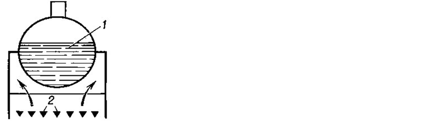
Figure 1. Cylinder steam boiler of the 19th century 1―drum; 2―fire grates.
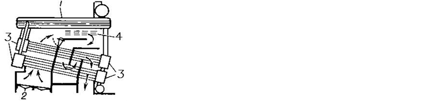
Figure 2. Simple header boiler 1―drum; 2―fire grate; 3―collection chamber; 4―superheater.
2.2. Laws of Heat Radiation from Solid Bodies
For calculating the radiation from solid fuel and solid surface of the refractory lining, the law that bears the name Stefan-Boltzmann was experimentally established by Y. Stefan in 1879 and then theoretically substantiated by L. Boltzmann in 1884.
 (1)
(1)
where q is the flux surface density, radiated from solid body (fuel, lining) in the direction perpendicular to its surface, ε1 is the solid emissivity factor; сS is Stefan-Boltzmann constant; Т1 is the solid temperature.
The average heating flux surface density, radiated from solid body, fuel to the barrel (Figure 1) or water tubes (Figure 2) in a steam boiler box is determined from the expression [1] :
 (2)
(2)
where εred is the fuel-tube drum reduced radiation coefficient; T2 is the temperature of tube drum surface; φ11 is the angular coefficient of the fuel radiation onto the drum surface or tubes; F1, F2 are fuel and drum surface areas accordingly on which fuel radiation is incident.
At the beginning of the XX century Planck and Wien (Nobel Prize Winners in Physics, thereafter) established the laws that bear their names. Planck’s law characterizes spectral radiant intensity distribution of black body along the wavelength against the temperature. Wien’s law allows to determine the wavelength, at which density of black body radiation attains its maximum value.
Kirchhoff’s law suggests that ratio between surface density of real body radiation and absorption body coefficient is equal for all the bodies at the same temperature and equals surface density of black body radiation at the temperature given. According to Lambert’s law, the body irradiance in the direction, making an angle α with the normal to a body surface is directly proportional to cosine of this angle.
Solid fuel gas takes an active part in heat transfer and process of vaporization in a steam boiler box (Figure 2).
2.3. Calculation of Heat Transfer in Torch Furnaces, Fire Boxes, Combustion Chambers Using Solid Bodies Radiation
Throughout the 20th century, calculations of radiation from torch to water pipes were calculated by the equation (2). Volume gas radiation was replaced by hard surface radiation, bounding gas. However, gas is the selectively radiating body, i.e. radiates heating flux in a definite wavelength range. In the 20th century a lot of experiments on emission bands, CO2 absorption, and gas-emission coefficient were carried out. The main gas radiation sources are triatomic gases CO2 and H2O. Experience has shown that CO2 radiation is proportional to the 3.5 power of the temperature and H2O radiation to the 3 power of the temperature. By the mid-twentieth century the graphs of CO2 and H2O radiation coefficients and norm-based method of steam boiler heat calculation were plotted [4] .
Let us consider the modern fire box of steam boiler and heat transfer calculation in it. The steam boiler firebox of a 300MW power unit has the shape of a rectangular parallelepiped with height Н = 35 m, width а = 14 m, and depth b = 7 m. The vertical water pipes fill the furnaces on the inside. Occupy the entire space of the firebox chamber. Over the entire firebox height, the torch has the shape of elliptical cylindrical gas volume in which two or more circular cylindrical gas volumes can be inscribed. Isotherms divide the circular cylindrical gas volumes along the height into several isothermal circular cylindrical or into a few tens of isothermal circular cylindrical gas volumes.
The boiler operates on fuel oil, 16 burners (Figure 3(a)) illustrates thereof by arrows ) with total throughput Вк = 67 t/h are opposite installed in 2 tiers by 8 burners in each at a height of 3 and 6 m from hearth surface.
The fuel oil heating value  = 41 MJ/kg, the fuel flow rate k = 0.162 kg/h [2] . During the operation of 36 burners with a throughput of 5.2 t/h, the fuel flow rate will be Bf = 187.2 × 10 3 kg/h, and the torch power will be Pt = 2155 MW. Figure 3(a) shows isotherm location along the furnace height. The torch fills the entire firebox over its height and perimeter and has the shape of elliptical rectangular parallelepiped. Isotherms divide the elliptical rectangular parallelepiped along the height into seven volume zones. The modern zonal method for calculating heat transfer in firebox consists in the following calculation procedures. The firebox of a steam boi-
 (a) (b) (c)
Figure 3. Steam boiler box and distribution of isotherms along its height (а); dividing the furnace into the calculating zones (b); results of calculation of radiation flux density distribution over the front wall symmetry axis (c).
ler is decomposed in accordance with isotherms location along the height into 11 volume and 46 surface zones (Figure 3(b)). The system of integral-differential equations describing radiant heat transfer approximated by the system of algebraic equations is worked out [1] . Radiation from rectangular gas volumes is replaced by the radiation from rectangular parallepipeds surfaces in the system of algebraic equations. In the system of algebraic equations heat radiation from surfaces is determined by Stefan-Boltzmann law (2). Calculation results of distribution of radiant flux densities over the frontal wall vertical axis are presented in (Figure 3(c)). Calculated-experimental data comparison (Figure 3(c)), [5] shows that the difference between the calculated data and measurement data over the furnace height may be accounted for 10% - 40%. Analogous method for calculation is used for the analysis heat transfer in torch furnaces, combustion chambers of gas.
2.4. Crisis of Method for Calculating Heat Transfer in Torch Furnaces, Fireboxes, and Combustion Chambers Based on Black Body Radiation Laws
Despite the fact that abovementioned method for calculating heat transfer has been improved for the XX century and has become an engineering calculation method, it still has certain shortcomings:
1) in calculating radiation from gas, black bodies radiation laws, Stefan-Boltzmann’s law, which was derived for calculating radiation from solid bodies are used;
2) the differential and algebraic equations of heat transfer are not analytical expressions, which crown the development of any theory if it is possible to solve differential equations;
3) gas volume radiation in calculations are replaced by surface radiation with unacknowledging radiation of 40 × 1030 particles in the torch volume, that is a gross error;
4) calculated results give a limited information content with a significant error, often inaccurate.
Review of centenary operating experience, calculation, design of flame furnaces, fire boxes, and combustion chambers of gas-turbine plants shows inconsistence of heat exchange theory with exploitation practice. By now, quite a number of facts have been revealed that point to the need of developing the modern theory of volume radiation in torch furnaces, fireboxes, and combustion chambers. Rise of flame temperature without its expansion doesn’t lead to increase in furnace efficiency. At the same flame temperature but different power, generated in it, the radiation fluxes, incident on heating surfaces will be different. Combustion product recycling is made to decrease the yield of nitric oxide. It decreases the torch temperature and the yield of nitric oxide without decrease in its capacity. This fact proves the determining influence of fuel rate, but not a torch temperature on heat transfer in torch furnaces, fire boxes, and combustion chambers.
The torch power can be increased by heating the air. For example, with air heated to 600˚C, the torch power increased by 17%, and its temperature rose from 1300˚C to 2000˚C in a torch heating furnace [2] . According to expression (2), the density of total heat flux radiated from the torch to the calculated zone should increase by a factor of 5, which is in contradiction with the energy conservation law. Under the real conditions of furnace operation, with air subjected to preheating and with the torch power increased by 17%, the heat flux density and the heating rate increase by 15% - 17%, i.e., in direct proportion to the growth of torch power and not to the fourth power of temperature [6] .
3. Crisis of Calculation and Development the Modern Heat Transfer Theory in Torch Furnaces and Plasma-Arc Steel-Melting Furnaces
3.1. Crisis of Calculation Heat Transfer in Torch Furnaces by the Laws of Radiation from Solid Bodies
In Arc-Steel-Melting Furnaces (ASFs), in which 35% of all steel in the world are melted, design average arc temperature in 3-6-t and 100-150-t furnaces is the same and accounts for about 6000˚С [2] . In 1920-70s attempts to use blackbody radiation laws, Stefan-Boltzmann law for calculating heat transfer in ASF didn’t lead to success. Equation (2) derives equal heat flow density from arc to the metal in 3-t furnaces either in 150-t furnaces, which is not the case for practical situations. Arc power is 0.6 MW in a 3-t furnace, 80 MW in 150-t furnace and furnace capacity is in direct proportion to arc power: capacity of 3-t furnace is 1t/h, and 200 t/h of 150-t.
Lack of method for calculating heat transfer in ASFs retarded its development. Nonuniformity of wall heating and metal temperature along the perimeter of furnace, tightening of charge melting at the slopes and other phenomena didn’t have scientific explanation. One cannot operate physical phenomenon without a knowledge of its investigation scene. As a result of photographing and high-speed shooting, we determined, that arc pattern presents the truncated cone in ASF. We determined by researches, that arc in ASF radiates 90% - 96% of its power [7] . The remainder 4% is transmissed to the metal and electrode by convection and heat conduction.
3.2. Modeling of Electric Arcs of Metallurgical Furnaces by Radiating Cylinders
In 1980 the author of this paper suggested to model arc by radiating cylinder in calculations and obtained formula for calculating radiation flux density from arc to the calculated area:
 , (3)
, (3)
where Рa―the arc power; α, β―the angles between radiation direction and normal to the axis and calculated area; r―the minimum distance from the arc center to the area; larc, lopen―the arc length and its open part, radiating to the calculation area; k―the furnace atmosphere attenuation coefficient.
Calculations by Formula (3) showed the justification for modeling an electric arc by cylinder source of heating radiation [8] . In the future, 16 formulas for calculating flux densities of radiation from arcs were obtained at any arc and heating surface attitude. Heat transfer theory in arc and plasma-arc steel melting furnaces is developed based on the formulas [9] [10] . As calculated and measurement results of heating fluxes in arc and plasma-arc steel-melting furnaces (PASFs) shown, the new theory allows us to obtain accurate results, which agree with measurement results. The theory explained many uncertain physical phenomena in ASF and PASF. Equation analysis (3) shows, that flow density of radiation from arc to the heating surface is directly proportional to the arc power and doesn’t depend on the temperature. In Equation (3) coefficient of radiation is also absent an undetectable coefficient of radiation from ionized gas. In Equation (3) angles α, β, distances larc, lopen, r are determined from geometrical constructions, thereof calculation presents no difficulty. Heat transfer theory was acknowledged by the international scientific community of metallurgists and electrochemists and is presently in use in training the students [2] , in developing new arc and plasma-arc steel melting furnaces [11] - [13] .
4. Laws of Radiation from Large Gas Volumes and Their Use for Calculating Heat Transfer in Torch Furnaces, Fire Boxes, Combustion Chambers
4.1. Laws of Radiation from Large Gas Volumes
Gas volumes radiation laws [3] , which allow to develop modern theory of heat transfer in torch furnaces, steam boiler boxes, combustion chambers of gas turbine plants [2] were disclosed in 2001. The modern theory of heat transfer is acknowledged by world community of power engineers and used as a textbook in power engineering and metallurgical education at a present time [2] . In the 17th-20th centuries in the scientific world there was a good tradition to name the law after the author, discovered it. It is evident nowadays, that this tradition doesn’t disappear.
Let us imagine the torch of steam boiler unit of 300 mW in the form of coaxial cylinder gas volumes (Figure 4).
Three hollow cylinders and a solid cylinder have a similar volume. Cylinders filled with an equal number of radiant particles, which are formed during the propellant reaction. Assume, the amount of coradiating particles in each radiating cylinder amounted to 10 × 1030, total particles accounts for 40 × 1030 and they are uniformly distributed over the volume. The residence time of particles in the furnace is 1 - 2 seconds, particle size is 0.2 - 0.4 μm.
The density of radiant flux falling on the tube surface area of a torch is determined by triple integral over the height H, perimeter P and radius r of large cylinder.
Radiation flux density, incident from torch on the calculated area of the furnace tube surface is determined by the triple integral along the height Н, perimeter P and radius r of a large cylinder volume, including radiation of all the 40 × 1030 radiating particles to the calculated area dF:
 (4)
(4)
where αi, βi―the angles between the radiation direction and normal, to the particle surface and calculated area accordingly; Рi―the emitted particle power; li―the particle-to-calculated area distance.
Solution of triple integral (4) is a cumbersome mathematical problem. Solution of calculation problem for gas bodies volume radiation was not found in the 20th century, so radiant gas volumes were unsuccessfully modeled by surface radiation from solid bodies in calculations.
In the 21st century the laws of radiation from gas volumes disclosed in 2001 came to the aid of volume radiation calculation [3] [14] . In [14] - [16] gas volumes radiation laws are stated. The essence is the following. The
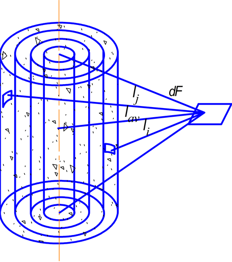
Figure 4. Radiation from coaxial cylinder gas volumes to the calculated area dF; li, lj, lav―the distance from the elementary radiation particles and arithmetic mean distance to the calculated area dF.
first law of radiation from large cylinder gas volumes: “Radiation view factors, the average path length of beams, the densities of radiation fluxes from isochoric coaxial cylinder volumes, filled with radiant gas to the calculation area are equal”.
 (5)
(5)
 (6)
(6)
 , (7)
, (7)
where ―the radiation view factors of the first-ith coaxial cylinder gas volumes;
 ?the radiation flux density, incident on the calculation area from the first-ith cylinder gas volume accordingly; lav,
 ―the average path length of beams from the first ith cylinder gas volume to the calculation area.
Radiation view factors characterize the fraction of radiation from cylinder gas volume on the calculation area from all volume radiation to the environment.
The second law: “The average path length of beams from coaxial cylindrical gas volumes to the calculation area is equal to the arithmetic mean distance from the symmetry axis of volumes to the calculation area”.
We assume that radiation of all 40 × 1030 particles achieve the area, then, according to the second law of radiation from coaxial cylinder gas volumes we can write:
 (8)
(8)
where li, lj, lk, ln, lav―the average beam path length, from radiant particles of the first-the fourth cylinder gas volumes and the arithmetic mean distance average from the symmetry axis to the calculation area dF.
From (8) follows, that the average beam path length of all 10 × 1030 radiating particles, uniformly filling each of the first-fourth cylinder volumes are equal. Besides, this distance equals the arithmetic mean distance from the symmetry axis, located inside of solid cylinder, to the calculating area dF. Confirmation of laws of volume radiation by the calculation results is in [14] [16] .
The third law: “The total density of radiation fluxes falling on the calculation area from a few radiating coaxial cylindrical gas volumes is equal to the density of radiation flux from a small diameter coaxial cylindrical gas volume falling on the calculation area at the radiation power releasing in a small diameter cylindrical gas volume and equal to the total radiation power releasing in all coaxial cylindrical gas volumes radiating on the calculation area”:
 (9)
(9)
Calculated results show [14] [16] , that if all the fuel is burnt in the central cylinder volume and 40 × 1030 radiative particles are generated, then heat flux density from the central cylinder volume on the calculation area is equal to the sum of heat fluxes densities of four coaxial cylinder gas volumes, in each of which 10 × 1030 radiative particles are generated in firing fuel.
From heat volume radiation laws follows, that radiation from isothermal coaxial cylindrical gas volumes is invariant, i.e., parameters and features of their radiation are equal. Hence, heat radiation of any high-powered large cylinder gas volume may be equivalently replaced by equal powered radiation from coaxial cylinder gas volume of a small diameter. Owing to gas volume heat radiation laws, researchers have no need to carry out triple and quadruple integration in calculating radiant heat transfer. It is possible to determine parameters of radiation from cylinder gas volumes by carrying out single integration of the geometrical and trigonometrical dependences for a small diameter coaxial cylindrical volume.
By integrating the geometrical dependences between cylinder radiating volume of a small diameter and heating surfaces with any spatial positions thereof, the author of this article has in fact solved the problems of determining the parameters of radiation from the above-mentioned bodies and surfaces [2] .
Thus, method for calculating heating fluxes from gas volumes, considering radiation from full set of particles in gas volume was established for the first time.
4.2. Heat Transfer Calculation in Torch Furnaces, Fire Boxes, Combustion Chambers Using Gas Volumes Radiation Laws
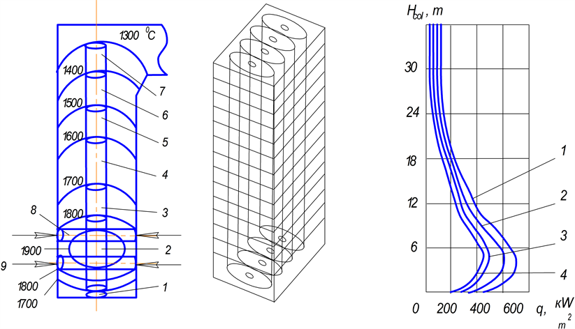
Let us consider heat transfer in steam boiler box of 300 MW with the use of large gas volumes radiation laws. In accordance with laws of radiation from coaxial cylinder gas volumes, we model the torch by 1 - 7 tiers of vertical cylinder sources by 4 cylinder sources in each tier In accordance to laws of radiation from gas volumes, we model the torch by 7 tiers of 1-7 vertical cylinder sources by 4 cylinder sources in each tier and 2 tiers (8 and 9) of cylinder sources by 4 horizontal cylinder sources in each tier, while they located on the extension of the burners axes (Figure 5(a)).
a 1 - 7 the first-the seventh tiers of vertical cylinder sources accordingly; 8, 9―the eighth, the ninth tiers of horizontal cylinder sources accordingly;
c heat flux density: along the frontal wall vertical symmetry axis (1)―the calculated and measurement results; along the lateral wall vertical symmetry axis (2); along the later wall height 2 m off the vertical symmetry axis (3); along the frontal wall height 4.7 m off the vertical axis (4).
Let us determine the power, releasing in the torch by the equation:
 (10)
(10)
For calculating the distribution of power along the torch height, we form the proportion, in which torch zones temperatures and volumes are used. A proportion for calculating power, releasing in each volume zones may be formed for any torch [2] :
 (11)
(11)
where Р1, Рi―the powers, releasing in the first-the ith torch volume zones accordingly; Т1, Тi―the temperatures of the first-the ith volume zones accordingly.
The product obtained during calculation the proportion (11) torch power fraction, releasing in the torch volume zone into the torch power, gives the heating power, releasing in the volume zone given.
By the Equation (11), we obtained the powers generated in volume bodies, torch zones and the powers, generated in every cylinder radiation source of the 1 - 9 tiers (Figure 5(b)): Р1 = 15 MW; Р2 = 24 MW; Р3 = 24 MW; Р4 = 31 MW ; Р5 = 14 MW; Р6 = 14 MW; Р7 = 7,5 MW; Р8 = 33 MW; Р9 = 33 MW.
 (a) (b) (c)
Figure 5. Steam boiler box, distribution of isotherms and cylinder radiant sources by which the torch is modeled (а); division of the fire box by large cylinder radiant gas volumes (b); distribution of the radiation flux density over the walls (c).
We calculate the integral heat flux density incident from the torch on the following surfaces (Figure 5(c)): on the frontal wall over the wall’s vertical symmetry axis (1); on the frontal wall over the vertical line 4.7 m off the frontal wall vertical symmetry axis (4) or 2.3 m off the parallepiped side edge (firebox); on the sidewall along the vertical symmetry axis (2); on the sidewall along the vertical line 2.0 m off the sidewall vertical symmetry axis or 1.5 m off firebox side edge (3). Calculation of the incident integral radiation flux density from each cylinder source of horizontal and vertical volume zones on the ith wall surface elemental area was made by equation:
 (12)
(12)
where  is the local view factor of radiation from the jth cylindrical radiation source on the ith area, which is determined from the analytical expressions given in [2] ; Pj is the power of the jth cylindrical source, MW; Fi is the surface of the ith elemental area, m2; and l is the average beam path length, m.
The density of incident integral radiation flux from the torch on the ith elemental area is determined as the sum of integral heat flux densities from all cylindrical sources:
 (13)
(13)
The density of incident integral radiation flux from the torch on the ith elemental area is determined as the sum of integral heat flux densities from all cylindrical sources.
The density of incident integral radiation flux on the ith area caused by reflection of torch radiation from the bottom, ceiling, walls as well as the density of incident integral radiation flux from the radiant surfaces of the bottom, ceiling, walls and convective flux density is not determined due to the fact, that they add up to no more than 5% of incident integral heat flux density from the torch to the ith elementary area [2] .
According the measurement results, the distribution of integral radiation fluxes along the frontal and side vertical symmetry axis is the same and is characterized by curve 1 [17] .
The measurement results of integral radiation fluxes did not vary more than 10% from calculation results along the frontal wall vertical symmetry axis, testifying that the developed torch model of a steam boiler box adequately reflects the real one.
Zone of maximum heat release at height of 2 - 5 m from the back bottom is characterized by the maximal integral radiation flux densities from the flame on the frontal and lateral walls equaled to 680 kW/m2. Heat release in torch decreases along the torch height, as integral radiation flux densities from the torch decrease on the waterwall surfaces along the wall height. The densities of radiant fluxes on the lateral walls along the symmetry axis at height of 2 - 5 m equaled to 590 kW/m2, thereof decrease by 440 kW/m2 at a distance of 2 m from the symmetry axis at height of 2 - 5 m. The densities of radiant fluxes from the torch decrease by 250 kW/m2 at the periphery of the frontal wall situated at a height of 2 - 5 m.
Heat release in torch decreases along the torch height, as integral radiation flux densities from the torch decrease on the waterwall surfaces along the wall height.
The calculated data of distribution of integral radiant heat flux density along the frontal wall width of steam boiler box agree closely with the results from measurements of deposits inside the tubes.
The deposits are distributed ununiformly over the tube water wall surfaces: the maximal number thereof are observed in the zone of the largest heat flow near the burners (along the furnace height) and in the center of each wall [18] , the minimal―at the furnace wall periphery.
Heat transfer in torch heating furnaces, combustion chambers of gas-turbine plants is calculated in a similar way [2] [19] .
5. Conclusions
The flame model in the form of a volume consisting of a multitude of coaxial radiating cylindrical gas volumes is used in calculating radiant heat transfer in torch heating furnaces, in steam boiler fireboxes, in the combustion chambers of gas turbine units. The calculation results are in good agreement with the results obtained from measurements of heat fluxes in fireboxes, furnaces, and combustion chambers.
The discovery enabled us to design new torch furnaces, fire boxes, combustion chambers of gas-turbine plants. On the basis of disclosed laws for radiation from large gas volumes, 20 innovative steam boiler boxes, torch heating and electric arc melting furnaces, combustion chambers, ways of heating and melting the metal, providing the improvement in the quality of production, reduction in time of heating and melting the metal, improving the efficiency of plants, decrease by 8% - 18% in fuel and electric energy consumption, unit pollutant emissions [20] - [23] .
Fuel firing is being used up in furnaces, steam boiler boxes, combustion chambers of gas-turbine plants at a present time. The disclosure of gas volume radiation laws [6] is as important for scientific and technological development, creation of innovative torch furnaces, steam boiler boxes, combustion chambers of gas-turbine plants as disclosure of blackbody radiation laws, laws of Planck, Wien, Stefan-Boltzmann, Kirchhoff for creation and development solid fuel furnaces, fire grate furnaces, steam-engines of locomotives, steamers, performed scientific and technical revolution in the late XIX-early XX centuries.
Cite this paper
Anatoliy NikolaevichMakarov, (2015) Laws of Heat Radiation from Surfaces and Gas Volumes. World Journal of Engineering and Technology,03,260-270. doi: 10.4236/wjet.2015.34027
References
- 1. Blokh, A.G., Zhuravlev, Yu.A. and Ryzhkov, L.N. (1991) Radiant Heat Transfer. A Handbook, Energoatomizdat, Moscow, 432 p. (In Russian)
- 2. Маkarov, A.N. (2014) Heat Transfer in Electric Arc and Torch Metallurgical Furnaces and Energy Plants. Lan', St. Petersburg, 384 p.
- 3. Makarov, A.N. (2012) A Regular Correlation between the Parameters Characterizing Radiation from Isothermal Coaxial Cylindrical Gas Layers Generated during Flame Combustion of Fuel and Electric Arc Burning in Metal Vapors at Atmospheric Pressure (Makarov’s Regularities), Diploma No. 47. In: Pototskii, V.V., Ed., Scientific Disclosures: A Collection of Brief Descriptions of Scientific Disclosures, Scientific Ideas, and Scientific Hypotheses—2011, RAEN, Moscow, 33-37. (In Russian)
- 4. Thermal Design of Boiler Units (1973) A Standard Method. Energiya, Moscow, 273 p. (In Russian)
- 5. Usman, Yu.M., Enyakin, Yu.P., Filatov, A.V. and Shtalman, S.G. (1985) Comparison of the Gas, Fuel Oil Flaring Study and Their Mix in Boiler Box of TGMP-314P with Bottom Downward Firing. No. 1, Electricheskiye stancii, 25-36.
- 6. Makarov, A.N. (2014) Theory of Radiative Heat Exchange in Furnaces, Fire Boxes, Combustion Chambers Is Replenished by Four New Laws. Science Discovery, 2, 34-42.
http://dx.doi.org/10.11648/j.sd.20140202.12 - 7. Nikol’skii, L.E., Smolyarenko, V.D. and Kuznetsov, L.N. (1981) Thermal Operation of Arc Steel Melting Furnaces. Metallurgiya, Moscow. (In Russian)
- 8. Makarov, A.N. and Svenchanskii, A.D. (1992) Optimal Operating Conditions of Arc Steel Melting Furnaces. Energoatomizdat, Moscow. (In Russian)
- 9. Makarov, A.N, Rybakova, V.V. and Galicheva, M.K. (2014) Electromagnetism and the Arc Efficiency of Electric Arc Steel Melting Furnaces. Journal of Electromagnetic Analysis and Application, 6, 184-192.
http://dx.doi.org/10.4236/jemaa.2014.67018 - 10. Makarov, A. N. (1994) Heat Transfer Theory in Arc Furnaces for Steel Melting: DEA Thesis, Saint-Petersburg Electrotechnical University, St. Petersburg, 354 p.
- 11. Makarov, A.N. and Sokolov, A.Yu. (2010) Electrical, Geometric, and Thermal Parameters of Arc in Metallic Vapors. Russian Metallurgy (Metally), 2010, 1136-1140.
- 12. Makarov, A.N., Lugovoi, Y.A. and Zuikov, R.M. (2011) Energy Saving for Steelmaking in Plasma-Arc Furnaces. Russian Metallurgy (Metally), 2011, 526-530.
http://dx.doi.org/10.1134/S0036029511060152 - 13. Makarov, A.N., Sokolov, A.Y. and Lugovoi, Y.A. (2012) Increasing the Arc Efficiency by the Removal of Arc Electromagnetic Blowing in Electric Arc Furnaces: I. Effect of Electromagnetic Blowing and the Slag Height on the Arc Efficiency in an Electric Arc Furnace. Russian Metallurgy (Metally), 2012, 542-547.
http://dx.doi.org/10.1134/S0036029512060134 - 14. Makarov, A.N. (2014) Theory of Radiative Heat Exchange in Furnaces, Fire Boxes, Combustion Chambers Is Replenished by Four New Laws. Science Discovery, 2, 34-42.
http://dx.doi.org/10.11648/j.sd.20140202.12 - 15. Makarov, A.N. (2014) Regularities Pertinent to Heat Transfer between Torch Gas Layers and Steam Boiler Firebox Waterwalls. Part I. Geometrical and Physical Torch Model as a Source of Heat Radiation. Thermal Engineering, 61, 642-648.
http://dx.doi.org/10.1134/S004060151406007X - 16. Makarov, A.N. (2014) Regularities Pertinent to Heat Transfer between Torch Gas Layers and Steam Boiler Firebox Waterwalls. Part II. Gas Layer Radiation Laws and the Procedure for Calculating Heat Transfer in Furnaces, Fire Boxes, and Combustion Chambers Developed on the Basis of These Laws. Thermal Engineering, 61, 717-723.
http://dx.doi.org/10.1134/S0040601514100073 - 17. Abrutin, A.A., Antonov, A.Y., Usman, Y.M., Stilman, S.G. and Levin, M.M. (1981) Heat Transfer Features in Oil-Fired Unit with Hearth Layout of Burners. Electric Stations, 9, 27-30.
- 18. Kozlov, Y.V., Zroichikova, T.V. and Belov V.A. (2003) Ways of Improving the Reliability of Furnace Waterwalls. Electricheskiye Stancii, 5, 17-19.
- 19. Makarov, A.N. (2014) Regularities Pertinent to Heat Transfer between Torch Gas Layers and Steam Boiler Firebox Waterwalls. Part III. Examples of Heat Transfer Calculation in Torch Furnaces and Steam Boiler Fireboxes. Thermal Engineering, 61, 814-821.
http://dx.doi.org/10.1134/S0040601514110056 - 20. Makarov, A.N. and Shevchenko, M.N. (2010) Gas-Fuel Combustion Chamber. RF Patent No. 2400668.
- 21. Makarov, A.N. and Sheglov, A.G. (2012) A Regenerative Soaking Pit. RF Patent No. 2457262.
- 22. Makarov, A.N., Kruglov, E.V. and Rybakova, V.V. (2014) DC-Arc-Steel Melting Furnace. RF Patent No. 2516896.
- 23. Makarov, A.N., Kruglov, E.V. and Rybakova, V.V. (2014) Heating Furnace with a Ring Bottom. RF Patent No. 2517079.