Paper Menu >>
Journal Menu >>
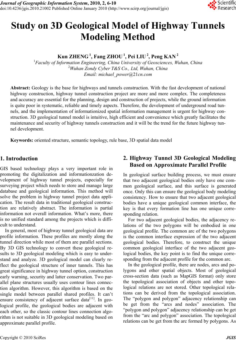 Journal of Geographic Information System, 2010, 2, 6-10 doi:10.4236/jgis.2010.21002 Published Online January 2010 (http://www.scirp.org/journal/jgis) Copyright © 2010 SciRes JGIS Study on 3D Geological Model of Highway Tunnels Modeling Method Kun ZHENG 1, Fang ZHOU 1, Pei LIU 2, Peng KAN 2 1Faculty of Information Engineering, China University of Geosciences, Wuhan, China 2Wuhan Zondy Cyber T&S Co., Ltd, Wuhan, C hi n a Email: michael_power@21cn.com Abstract: Geology is the base for highways and tunnels construction. With the fast development of national highway construction, highway tunnel construction project are more and more complex. The completeness and accuracy are essential for the planning, design and construction of projects, while the ground information is quite poor in systematic, reliable and timely aspects. Therefore, the develo pment of underground road tun- nels, and the implementation of informationized spatial information management is urgent for highway con- struction. 3D geological tunnel model is intuitiv e, high efficient and convenien ce which greatly facilitates the maintenance an d security of highway tunnels constru ction and it will be the trend for the future h ighway tun- nel development. Keywords: oriented structure, semantic topology, rule base, 3D spatial data model 1. Introduction GIS based technology plays a very important role in promoting the digitalization and informationzation de- velopment of highway tunnel projects, especially for surveying project which n eeds to store and manage large database and geological information. This method will solve the problem in highway tunnel project data appli- cation. The result data in traditional geological construc- tion are relatively abstract. The information is partial information not overall information. What’s more, there is no unified standard among the projects which is diffi- cult to understand. In general, most of highway tunnel geological data are profile information. These profiles are mostly along the tunnel direction while most of them are parallel sections. By 3D GIS technology to convert these geological re- sults to 3D geological modeling which is easy to under- stand and analyze. 3D geological model can clearly re- flect the geological structure of inner tunnels. This has great significance in highway tun nel option, construction early warning, security and latter conservatio n. Two par- allel plane structures usually uses contour lines connec- tion algorithm. However, this algorithm is based on the single model between parallel shared profiles. It can’t ensure consistency of adjacent surface data[11]. In geo- logical profile, the geological bodies are adjacent with each other, so the classic contour lines connection algo- rithm is not suitable in 3D geological modeling based on approximate parallel profile. 2. Highway Tunnel 3D Geological Modeling Based on Approximate Parallel Profile In geological surface building process, we must ensure that two adjacent geological bodies only have one com- mon geological surface, and this surface is generated once. Only this can ensure the geological body modeling consistency. How to ensure that two adjacent geological bodies have a unique geological common interface, the key is that every formation line has one unique corre- sponding relation. For two adjacent geological bodies, the adjacency re- lations of the two polygons will be embodied in one geological profile. The common arc of the two polygons is the common interface expression of the two adjacent geological bodies. Therefore, to construct the unique common geological interface of the two adjacent geo- logical bodies, the key point is to find the unique corre- sponding from the adjacent profile for the common arc. In the geological profile, there are nodes, arcs and po- lygons and other spatial objects. Most of geological cross-section data (such as MapGIS format) only store the topological association of objects and other topo- logical relations are not stored. Other topological rela- tions can be derived from the topological association. The “polygon and polygon” adjacency relationship can be get from the “arcs and nodes” association. The “polygon an d polygon” adj acency r elationship can be g et from the “arc and polygon” association. The topological relations can be get from the arc formed by po lygons. As 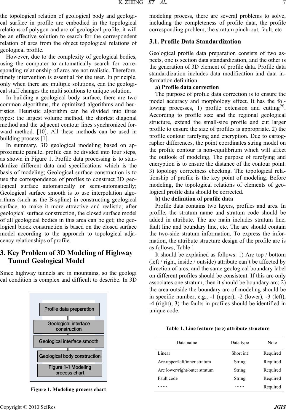 K. ZHENG ET AL. Copyright © 2010 SciRes JGIS 7 the topological relation of geological body and geologi- cal surface in profile are embodied in the topological relations of polygon and arc of geological profile, it will be an effective solution to search for the correspondent relation of arcs from the object topological relations of geological pr ofile. However, due to the complexity of geological bodies, using the computer to automatically search for corre- sponding relationship of arcs are not realistic. Therefore, timely intervention is essential for the user. In principle, only when there are multiple solutions, can the geologi- cal staff changes the multi solutions to unique solution. In building a geological body surface, there are two common algorithms, the optimized algorithms and heu- ristics. Heuristic algorithm can be divided into three types: the largest volume method, the shortest diagonal method and the adjacent contour lines synchronized for- ward method. [10]. All these methods can be used in building process [1]. In summary, 3D geological modeling based on ap- proximate parallel profile can be divided into four steps, as shown in Figure 1. Profile data processing is to stan- dardize different data and specifications which is the basis of modeling; Geological surface construction is to use the correspondence of profiles to construct 3D geo- logical surface automatically or semi-automatically; Geological surface smooth is to use interpolation algo- rithms (such as the B-spline) in constructing geological surface, to make it more attractive and realistic; after geological surface construction, the closed surface model of all geological bodies in this area can be get; the geo- logical block construction is based on the closed surface model according to the approach to topological adja- cency relationships of profile. 3. Key Problem of 3D Modeling of Highway Tunnel Geological Model Since highway tunnels are in mountains, so the geologi cal condition is complex and difficult to describe. In 3D Figure 1. Modeling process chart modeling process, there are several problems to solve, including the completeness of profile data, the profile corresponding problem, the stratum pinch-out, fault, etc 3.1. Profile Data Standardization Geological profile data preparation consists of two as- pects, one is section data standardization, and the other is the generation of 3D element of profile data. Profile data standardization includes data modification and data in- formation definition. a) Profile data correction The purpose of profile data correction is to ensure the model accuracy and morphology effect. It has the fol- lowing processes, 1) profile extension and cutting[9]. According to profile size and the regional geological structure, extend the small-size profile and cut larger profile to ensure the size of profiles is appropriate. 2) the profile contour rarefying and encryption. Due to cartog- rapher differences, the point coordinates string model on the profile contour is non-equilibrium which will affect the outlook of modeling. The purpose of rarefying and encryption is to ensure the distance of the contour point. 3) topology correctness checking. The topological rela- tionship of profile is the key point of modeling. Before modeling, the topological relations of elements of geo- logical profile data should be corrected. b) the definition o f pr ofi le d ata Profile data contains two layers, profiles and arcs. In profile, the stratum name and stratum code should be added in attribute. The arc main includes stratum line, fault line and boundary line, etc. The arc should contain the two-side stratum information. To express the infor- mation, the attribute structure design of the profile arc is as follows, Table 1 It should be explained as follows: 1) Arc top / bottom (left / right, inside / outside) attribute can’t be affected by direction of arcs, and the same geological boundary label on different profiles should be consistent. If this arc only associates one stratum, then it should be boundary arc; 2) the area outside the boundary arc of modeling should be in specific number, e.g., -1 (upper), -2 (lower), -3 (left), -4 (right); 3) the faults in profiles should be identified in unique code. Table 1. Line feature (are) attribute structure Data name Data type Note Linear Short int Required Arc upper/left/inner stratum String Required Arc lower/right/out e r stratum String Required Fault code String Required …… …… Required 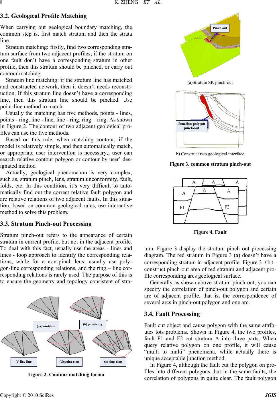 K. ZHENG ET AL. Copyright © 2010 SciRes JGIS 8 3.2. Geological Profile Matching When carrying out geological boundary matching, the common step is, first match stratum and then the strata line. Stratum matching: firstly, find two corresponding stra- tum surface from two adjacent profiles, if the stratum on one fault don’t have a corresponding stratum in other profile, then this stratum should be pinched, or carry out contour matching. Stratum line matching: if the stratum line has matched and constructed network, then it doesn’t needs reconstr- uction. If this stratum line doesn’t have a corresponding line, then this stratum line should be pinched. Use point-line method to match. Usually the matching has five methods, points - lines, points - ring, line - line, line - ring, ring – ring. As shown in Figure 2. The contour of two adjacent geological pro- files can use the five methods. Based on this rule, when matching contour, if the model is relatively simple, and then au tomatically match, or appropriate user intervention is necessary,; user can search relative contour polygon or contour by user’ des- ignated method Actually, geological phenomenon is very complex, such as, stratum pinch, lens, stratum unconformity, fault, folds, etc. In this condition, it’s very difficult to auto- matically find out the correct relative fault polygon and arc relative relations of two adjacent faults. In this situa- tion, based on common geological rules, use interactive method to solve this problem. 3.3. Stratum Pinch-out Processing Stratum pinch-out refers to the appearance of certain stratum in current profile, but not in the adjacent profile. To deal with this fact, usually use the areas - lines and lines - loop approach to identify the corresponding rela- tions, while for a non-pinch lens, usually use poly- gon-line corresponding relation s, and the ring – line cor- responding relations is rarely used. The purpose of this is to ensure the geometry and topology consistent of stra- Figure 2. Contour matching forma (a)Stratum SK pinch-out b) Construct two geologi c a l interface Figure 3. common stratum pinch-out Figure 4. Fault tum. Figure 3 display the stratum pinch out processing diagram. The red stratum in Figure 3 (a) doesn’t have a corresponding stratum in adjacent profile. Figure 3(b) construct pinch-out area of red stratum and adjacent pro- file corresponding arcs geological surface. Generally as shown above stratum pinch-out, you can specify the correlation of pinch-out polygon and certain arc of adjacent profile, that is, the correspondence of several arcs in pinch-out polygon and one arc. 3.4. Fault Processing Fault cut object and cause polygon with the same attrib- utes lots problems. Shown in Figure 4, the two profiles, fault F1 and F2 cut stratum A into three parts. When query relative polygon on one profile, it will cause “multi to multi” phenomena, while actually there is unique acceptable junction method. In Figure 4, although th e fault cut the polygon on pro- files into different polygons, but in the same faults, the correlation of polygons in quite clear. The fault polygon 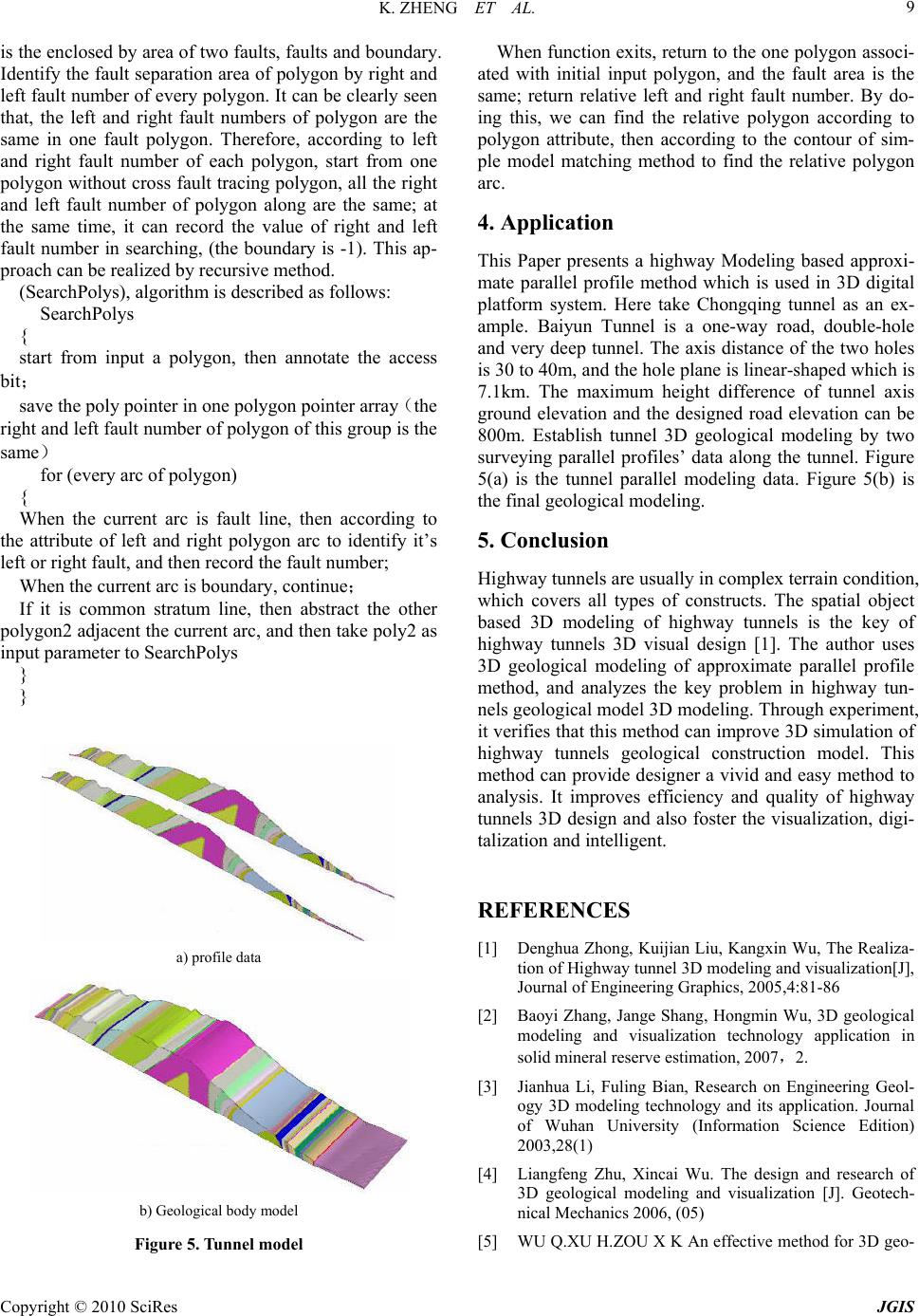 K. ZHENG ET AL. Copyright © 2010 SciRes JGIS 9 is the enclosed by area of two faults, faults and boundary. Identify th e fault separation area of polygon by right and left fault number of every polygon. It can be clearly seen that, the left and right fault numbers of polygon are the same in one fault polygon. Therefore, according to left and right fault number of each polygon, start from one polygon withou t cross fault tracing polygon, all the right and left fault number of polygon along are the same; at the same time, it can record the value of right and left fault number in searching, (the boundary is -1). This ap- proach can be realized by recursive method. (SearchPolys), algorithm is described as follows: SearchPolys { start from input a polygon, then annotate the access bit; save the poly pointer in one polygon pointer array(the right and left fault nu mber of polygo n of this group is the same) for (every arc of polyg on ) { When the current arc is fault line, then according to the attribute of left and right polygon arc to identify it’s left or right fault, and then record the fault number; When the current arc is boundary, continue; If it is common stratum line, then abstract the other polygon2 adj acent the current arc, and then take poly2 as input parameter to SearchPolys } } a) profile data b) Geological body model Figure 5. Tunnel model When function exits, return to the on e polygon associ- ated with initial input polygon, and the fault area is the same; return relative left and right fault number. By do- ing this, we can find the relative polygon according to polygon attribute, then according to the contour of sim- ple model matching method to find the relative polygon arc. 4. Application This Paper presents a highway Modeling based approxi- mate parallel profile method which is used in 3D digital platform system. Here take Chongqing tunnel as an ex- ample. Baiyun Tunnel is a one-way road, double-hole and very deep tunnel. The axis distance of the two holes is 30 to 40m, and the hole plane is linear-shaped which is 7.1km. The maximum height difference of tunnel axis ground elevation and the designed road elevation can be 800m. Establish tunnel 3D geological modeling by two surveying parallel profiles’ data along the tunnel. Figure 5(a) is the tunnel parallel modeling data. Figure 5(b) is the final geological modeling. 5. Conclusion Highway tunnels are usually in complex terrain condition, which covers all types of constructs. The spatial object based 3D modeling of highway tunnels is the key of highway tunnels 3D visual design [1]. The author uses 3D geological modeling of approximate parallel profile method, and analyzes the key problem in highway tun- nels geological model 3D mod eling. Thr ough exper iment, it verifies that this method can improve 3D simulation of highway tunnels geological construction model. This method can provide designer a vivid and easy method to analysis. It improves efficiency and quality of highway tunnels 3D design and also foster the visualization, digi- talization and intelligent. REFERENCES [1] Denghua Zhong, Kuijian Liu, Kangxin Wu, The Realiza- tion of Highway tunnel 3D modeling and visualization[J], Journal of Engineering Graphics, 2005,4:81-86 [2] Baoyi Zhang, Jange Shang, Hongmin Wu, 3D geological modeling and visualization technology application in solid mineral reserve estimation, 2007,2. [3] Jianhua Li, Fuling Bian, Research on Engineering Geol- ogy 3D modeling technology and its application. Journal of Wuhan University (Information Science Edition) 2003,28(1) [4] Liangfeng Zhu, Xincai Wu. The design and research of 3D geological modeling and visualization [J]. Geotech- nical Mechanics 2006, (05) [5] WU Q.XU H.ZOU X K An effective method for 3D geo-  K. ZHENG ET AL. Copyright © 2010 SciRes JGIS 10 logical modeling with multi-source data integration 2005(1) [6] Honggang Qu, Mao Pan, Yong Wang.3D Geological modeling based on profiles with topology [J]. Journal of Peking University (Natural Science Edition) 2006.6 [7] Jing Ming, Mao Pan, Honggang Qu. 3D geological mul- ti-body modeling based on mesh profile with topology [J], Journal of Geotechnical Engineering. 2008 30(9) [8] Guoliang Chen, Liangfeng Zhu, Xiuguo Liu. The Crossed Profile Consistent Checking Method of 3D Geological Structure modeling [J] Xinyang Normal University (Nat- ural Science Edition) 2009,(03) . [9] Baoyi Zhang, Multi-constraint geological modeling technology research [D], Wuhan, China University of Geosciences based on profiles. 2007 [10] GANAPATHY S, DENNEHY T G. A New general tri- angulation method for planar contours[J].SIGGRAPH Computer Graphics, 1986,16(3):69-75. [11] Yong Wang, Sheng Xue, Pan Mao. 3D Profile Vector Data Automatically Generation Algorithm Based on Pro- file Topology[J], Computer Engineering and Applications, 2003,39 (5) :1-2. [12] MEYERS D,SKINNERS,SLOAN K.Surfaces from con- tours[J].ACMTransationOnGrahpics,1992,11(3):228-258. |