Paper Menu >>
Journal Menu >>
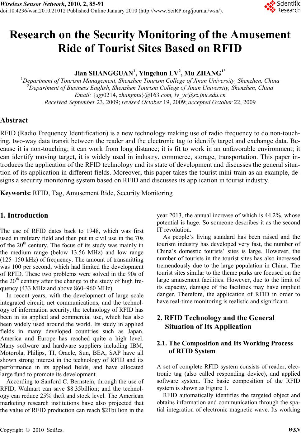 Wireless Sensor Network, 2010, 2, 85-91 doi:10.4236/wsn.2010.21012 ublished Online January 2010 (http://www.SciRP.org/journal/wsn/). Copyright © 2010 SciRes. WSN P Research on the Security Monitoring of the Amusement Ride of Tourist Sites Based on RFID Jian SHANGGUAN1, Yingchun LV2, Mu ZHANG1* 1Department of Tourism Manageme nt , Shenzhen Tou ri s m C oll e ge of Jinan University, Shen zhen, China 2Department of Business English, Shenzhen Tourism College of Jinan University, Shenzhen, China Email: {sgj0214 , zhangmu}@163.com, lv_yc@sz.jnu.edu.cn Received September 23, 2009; revised October 19, 2009; accepted October 22, 2009 Abstract RFID (Radio Frequency Identification) is a new techn ology making use of radio frequency to do non-touch- ing, two-way data transit between the reader and the electronic tag to identify target and exchange data. Be- cause it is non-touching; it can work from long distance; it is fit to work in an unfavorable environment; it can identify moving target, it is widely used in industry, commerce, storage, transportation. This paper in- troduces the application of the RFID technology and its state of development and discusses the general situa- tion of its application in different fields. Moreover, this paper takes the tourist mini-train as an example, de- signs a security monitoring system based on RFID and discusses its application in tourist industry. Keywords: RFID, Tag, Amusement Ride, Security Monitoring 1. Introduction The use of RFID dates back to 1948, which was first used in military field and then put in civil use in the 70s of the 20th century. The focus of its study was mainly in the medium range (below 13.56 MHz) and low range (125–150 kHz) of frequency. The amount of transmitting was 100 per second, which had limited the development of RFID. These two problems were solved in the 90s of the 20th century after the change to the study of high fre- quency (433 MHz and abov e 860–960 MHz). In recent years, with the development of large scale integrated circuit, net communications, and the technol- ogy of information security, the technology of RFID has been in its applied and commercial use, which has also been widely used around the world. Its study in applied fields in many developed countries such as Japan, America and Europe has reached quite a high level. Many software and hardware suppliers including IBM, Motorola, Philips, TI, Oracle, Sun, BEA, SAP have all shown strong interest in the technology of RFID and its performance in its applied fields, and have allocated large fund to promote its development. According to Sanford C. Bern stein, through the use of RFID, Walmart can save $8.35billion; and the technol- ogy can reduce 25% theft and stock level. The American marketing research institutions have also projected that the value of RFID production can reach $21b illion in the year 2013, the annual increase of which is 44.2%, whose potential is huge. So someone describes it as the second IT revolution. As people’s living standard has been raised and the tourism industry has developed very fast, the number of China’s domestic tourists’ sites is large. However, the number of tourists in the tourist sites has also increased tremendously due to the large population in China. The tourist sites similar to the the me parks are focused on the large amusement facilities. However, due to the limit of its capacity, damage of the facilities may have implicit danger. Therefore, the application of RFID in order to have real-time monitoring is realistic and significant. 2. RFID Technology and the General Situation of Its Application 2.1. The Composition and Its Working Process of RFID System A set of complete RFID system consists of reader, elec- tronic tag (also called responding device), and applied software system. The basic composition of the RFID system is shown as Figure 1. RFID automatically identifies the targeted object and obtains information and communication through the spa- tial integration of electronic magnetic wave. Its working 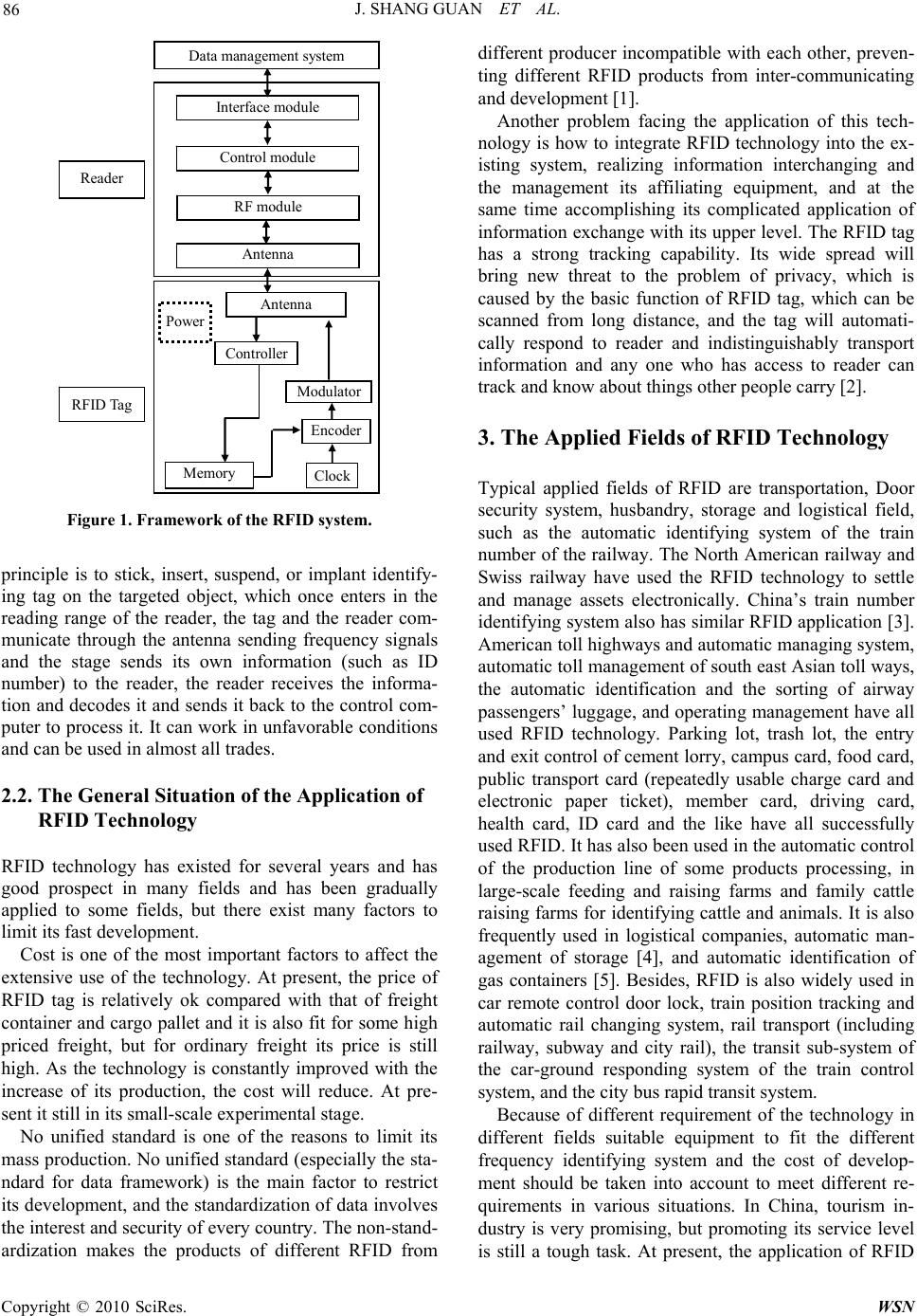 J. SHANG GUAN ET AL. 86 Reader RFI D Tag Power RF module Antenna Interface module Control module Clock Memory Modulator Antenna Encoder Data management system Controller Figure 1. Framework of the RFID system. principle is to stick, insert, suspend, or implant identify- ing tag on the targeted object, which once enters in the reading range of the reader, the tag and the reader com- municate through the antenna sending frequency signals and the stage sends its own information (such as ID number) to the reader, the reader receives the informa- tion and decodes it and sends it back to the control com- puter to process it. It can work in unfavorable co nditions and can be used in almost all trades. 2.2. The General Situation of the Application of RFID Technology RFID technology has existed for several years and has good prospect in many fields and has been gradually applied to some fields, but there exist many factors to limit its fast development. Cost is one of the most important factors to affect the extensive use of the technology. At present, the price of RFID tag is relatively ok compared with that of freight container and cargo pallet and it is also fit for so me high priced freight, but for ordinary freight its price is still high. As the technology is constantly improved with the increase of its production, the cost will reduce. At pre- sent it still in its small-scale experimental stage. No unified standard is one of the reasons to limit its mass production. No unified standard (especially the sta- ndard for data framework) is the main factor to restrict its development, and the standardization of data involves the interest and security of ever y coun tr y. Th e non- stan d- ardization makes the products of different RFID from different producer incompatible with each other, preven- ting different RFID products from inter-communicating and development [1]. Another problem facing the application of this tech- nology is how to integrate RFID technology into the ex- isting system, realizing information interchanging and the management its affiliating equipment, and at the same time accomplishing its complicated application of information exchange with its up per level. The RFID tag has a strong tracking capability. Its wide spread will bring new threat to the problem of privacy, which is caused by the basic function of RFID tag, which can be scanned from long distance, and the tag will automati- cally respond to reader and indistinguishably transport information and any one who has access to reader can track and know about things other people carry [2]. 3. The Applied Fields of RFID Technology Typical applied fields of RFID are transportation, Door security system, husbandry, storage and logistical field, such as the automatic identifying system of the train number of the railway. The North American railway and Swiss railway have used the RFID technology to settle and manage assets electronically. China’s train number identifying system also has similar RFID application [3 ]. American toll highways and automatic managing system, automatic toll management of south east Asian toll ways, the automatic identification and the sorting of airway passengers’ luggage, and operating management have all used RFID technology. Parking lot, trash lot, the entry and exit control of cement lorry, campus card, food card, public transport card (repeatedly usable charge card and electronic paper ticket), member card, driving card, health card, ID card and the like have all successfully used RFID. It has also been used in the automatic control of the production line of some products processing, in large-scale feeding and raising farms and family cattle raising farms for identifying cattle and animals. It is also frequently used in logistical companies, automatic man- agement of storage [4], and automatic identification of gas containers [5]. Besides, RFID is also widely used in car remote control door lock, train position tracking and automatic rail changing system, rail transport (including railway, subway and city rail), the transit sub-system of the car-ground responding system of the train control system, and the city bus rapid transit system. Because of different requirement of the technology in different fields suitable equipment to fit the different frequency identifying system and the cost of develop- ment should be taken into account to meet different re- quirements in various situations. In China, tourism in- dustry is very promising, but promoting its service level is still a tough task. At present, the application of RFID Copyright © 2010 SciRes. WSN 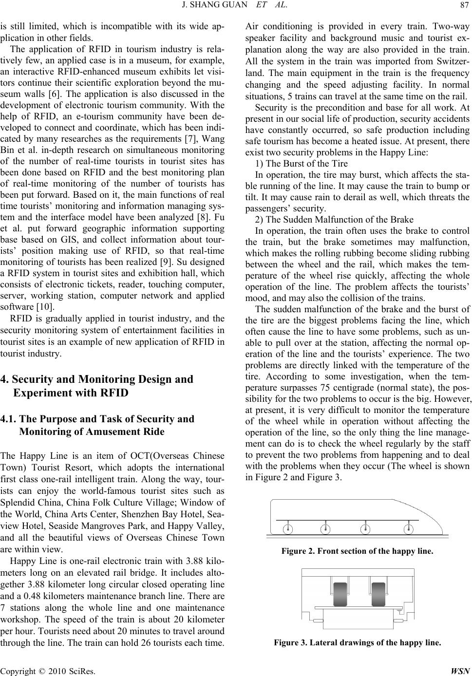 J. SHANG GUAN ET AL. 87 is still limited, which is incompatible with its wide ap- plication in other fields. The application of RFID in tourism industry is rela- tively few, an applied case is in a museum, for example, an interactive RFID-enhanced museum exhibits let visi- tors continue their scientific exploration beyond the mu- seum walls [6]. The application is also discussed in the development of electronic tourism community. With the help of RFID, an e-tourism community have been de- veloped to connect and coordinate, which has been indi- cated by many researches as the requirements [7], Wang Bin et al. in-depth research on simultaneous monitoring of the number of real-time tourists in tourist sites has been done based on RFID and the best monitoring plan of real-time monitoring of the number of tourists has been put forward. Based on it, th e main functions of real time tourists’ monitoring and information managing sys- tem and the interface model have been analyzed [8]. Fu et al. put forward geographic information supporting base based on GIS, and collect information about tour- ists’ position making use of RFID, so that real-time monitoring of tourists has been realized [9]. Su designed a RFID system in tourist sites and exhibition hall, which consists of electronic tickets, reader, touching computer, server, working station, computer network and applied software [10]. RFID is gradually applied in tourist industry, and the security monitoring system of entertainment facilities in tourist sites is an example of new applicatio n of RFID in tourist industry. 4. Security and Monitoring Design and Experiment with RFID 4.1. The Purpose and Task of Security and Monitoring of Amusement Ride The Happy Line is an item of OCT(Overseas Chinese Town) Tourist Resort, which adopts the international first class one-rail intelligent train. Along the way, tour- ists can enjoy the world-famous tourist sites such as Splendid China, China Folk Culture Village; Window of the World, China Arts Center, Shenzhen Bay Hotel, Sea- view Hotel, Seaside Mangroves Park, an d Happy Valley, and all the beautiful views of Overseas Chinese Town are within view. Happy Line is one-rail electronic train with 3.88 kilo- meters long on an elevated rail bridge. It includes alto- gether 3.88 kilometer long circular closed operating line and a 0.48 kilometers maintenance branch line. There are 7 stations along the whole line and one maintenance workshop. The speed of the train is about 20 kilometer per hour. Tourists ne ed about 20 minutes to tr avel around through the line. The train can hold 26 tourists each time. Air conditioning is provided in every train. Two-way speaker facility and background music and tourist ex- planation along the way are also provided in the train. All the system in the train was imported from Switzer- land. The main equipment in the train is the frequency changing and the speed adjusting facility. In normal situations, 5 trains can travel at the same time on th e rail. Security is the precondition and base for all work. At present in our social life of production, security accidents have constantly occurred, so safe production including safe tourism has become a heated issue. At present, there exist two security problems in the Happy Line: 1) The Burst of the Tire In operation, the tire may burst, which affects the sta- ble running of the line. It may cause the train to bump or tilt. It may cause rain to derail as well, which threats the passengers’ security. 2) The Sudden Malfunction of the Brake In operation, the train often uses the brake to control the train, but the brake sometimes may malfunction, which makes the rollin g rubbing become sliding rubbing between the wheel and the rail, which makes the tem- perature of the wheel rise quickly, affecting the whole operation of the line. The problem affects the tourists’ mood, and may also the collision of the trains. The sudden malfunction of the brake and the burst of the tire are the biggest problems facing the line, which often cause the line to have some problems, such as un- able to pull over at the station, affecting the normal op- eration of the line and the tourists’ experience. The two problems are directly linked with the temperature of the tire. According to some investigation, when the tem- perature surpasses 75 centigrade (normal state), the pos- sibility for the two problems to occur is the big. However, at present, it is very difficult to monitor the temperature of the wheel while in operation without affecting the operation of the line, so the only thing the line manage- ment can do is to check the wheel regularly by the staff to prevent the two problems from happening and to deal with the problems when they occur (The wheel is shown in Figure 2 and Figure 3. Figure 2. Front section of the happy line. Figure 3. Lateral drawings of the happy line. C opyright © 2010 SciRes. WSN  J. SHANG GUAN ET AL. Copyright © 2010 SciRes. WSN 88 4.2. The Design of the of Security and Monitoring System of the Happy Line Feedback (If the monitoring data is not within the scope of safety, the inspection of Happy Line is carried out in order to ensure the safe operation) Guara ntee of th e betimes and reliab i lit y i n networ k communication Collection of the required monitoring information Inner sensors with RFID chipReader Happy Line Guarantee of th e accur acy and noise immunity in data tra ns mission Central Controller (Monitor or P C) The system accomplishes two main tasks. First, Monitor the Happy Line all-roundly and along the whole line; Second, real-time (there exist a certain amount of ac- ceptable time-lag) measurement of the temperature of the surface of the rail and wheel to provide warning data to prevent sudd en malfunction of the wheel. Figure 4 is the working route of the system. Figure 4. The technical route of the safety monitoring of happy line. Detailed Design of the Software System Different information identifiable RFID tags are put on one side of the rail along the line every x meters and a reader is put in the train. When th e train enters in the tag identifiable range, the reader receives the information on the tag and sends it back to the center control through wireless communications technology (the cost is to be considered. If the cost is too high, double rubber wire connection will be used). The staff in the center control will get the information abou t the position of the train. Realization of its Software Sy stem 1)Set comm uni cat i on parameter before ope n t he port . Click “Port Set,” the parameters can be set as above (See Figure 6). 2) After finish the set, click “Port Open” to open the port (See Figure 7). MSG ORDER: Click the button, messages would be displayed by sort ascending. The tags with temperature sensor can be put in the wheels of the Happy Line (the RFID chips are clearable), and also the reader in the train can send the information about the temperature to the center control so that the staff in the Centre control will know the information about the temperature. When the temperature surpasses a certain degree, the train in a certain position will be warned against sudden malfunction of the wheel. Figure 5 is the chart or the principle of the monitoring and con- trol of the system. MSG RESET: clear the screen messages. CTRL OPT: Reader parameters set window. Thereafter, open the parameters window of the Reader. Set Address: Set reader address. The “Address.” can only be set once in order to ensure reader’s security. If you want to reset the “Address.”, you should initialize the reader first. Set Mode: There’re two modes in communication. Track of the train RFID Reader Different chips are identified by the reader Inner temperature sensor embedded in the tire o f the Happy Line Temperature data are transmit ted t o the reader Reader sent the wireless signal back to the center controller Passive RFID chips are identified by the reader when the trai n pass by and used for positioning. The direction of train movements Figure 5. Principle of the happy line monitoring system . Figure 7. Reader order menu. Figure 6.Communication parameters.  J. SHANG GUAN ET AL. 89 Figure 8. Reader parameters window. Figure 9. Interface of the temperature reading. Direct Mode: The reader sends to host once received data from tags. Buff Mode: The reader doesn’t send to host until re- ceived a command from host. In Buff Mode, the reader can save 100 pieces of latest messages. Set Interval: Interval is the permission time th at no tag data is received. It’s set in Buff Mode but used in Direct Mode. Thus, you should choose Buff Mode to set interval first, then choose Direct Mode. For instance, if set inter- val as “10”, the reader will send a sentence “0D 0D 07 55 FF FF 52” that means no data received from tags within 10 seconds. Set clock: Set real time clock in the read er. 3) After the parameters have been set, the Debugging program would work now. Click “Direct Mode”, it will show messages in the reader window (See Figure 8). No.: Number of tags that sent messages to readers. ReaderAddr: Add of readers CardNo: Tag’s number State: State of battery in a tag, if power is enough, it would show “OK ”, or it would show “low” which means the power is not enough now. Count: Amount of messages that a tag transmitted AllTime: Total time that tag detected by a reader, in other word, it’s the time sum from the first time the tag detected to the latest time it done. Div: Average interval that the tag received, “All- Time”/”Count”=Div Interval: Time between the latest message and its last second message of a tag Max: The largest interval Min: The shortest interval When too many messages display in the window, and you want to clear it, please click “CLR”. If click “Buff Mode”, message will not display unless you click “Read Buf Data”, then the messages would display in the Command window. 4) If want to stop the test, please click “Close” to quit (See Figure 9). 4.3. ExperimentalTtest and Data Analysis Identification of the maximum transmission distance between the chips on the temperature sensor and the reader. 1) Measurements in meters (See Table 1). 2) After the first step, if a signal is found in n meters, but not in n+1 meters, then measurement in centimeters will be taken between them (See Table 2). So we can get that the maximum transmission distance between the chips on the temperature sensor and the reader is 3.9meters. Test of the Respondi ng Time 1) Measure the time interval between the first catch of the temperature data by the device in the software of the Table 1. Measurement of the maximum transmission distance. Distance 1m2m 3m 4m N m Receive Signal or Not YesYes Yes No …… No Table 2. Further measurement of the maximum transmis- sion distance. Distance(n+0.1)m(n+0.2)m(n+0.3)m (n+0.4)m (n+0.9)m Receive Signal or Not Yes Yes Yes Yes …… Yes C opyright © 2010 SciRes. WSN 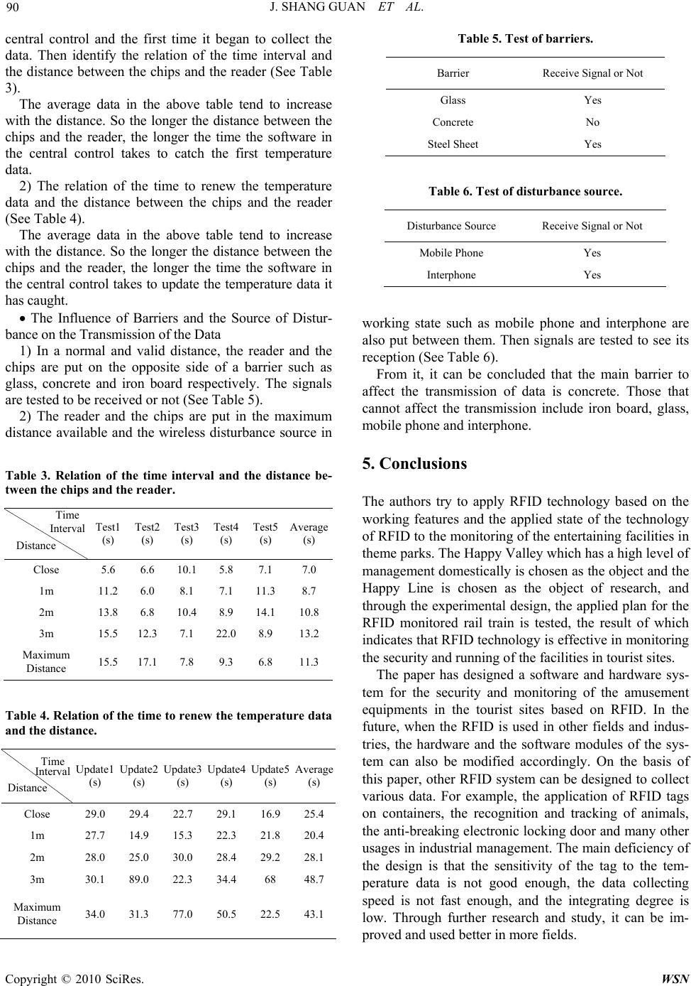 J. SHANG GUAN ET AL. 90 central control and the first time it began to collect the data. Then identify the relation of the time interval and the distance between the chips and the reader (See Table 3). The average data in the above table tend to increase with the distance. So the longer the distance between the chips and the reader, the longer the time the software in the central control takes to catch the first temperature data. 2) The relation of the time to renew the temperature data and the distance between the chips and the reader (See Table 4). The average data in the above table tend to increase with the distance. So the longer the distance between the chips and the reader, the longer the time the software in the central control takes to update the temperature data it has caught. The Influence of Barriers and the Source of Distur- bance on the Transmission of the Data 1) In a normal and valid distance, the reader and the chips are put on the opposite side of a barrier such as glass, concrete and iron board respectively. The signals are tested to be received or not (See Table 5). 2) The reader and the chips are put in the maximum distance available and the wireless disturbance source in Table 3. Relation of the time interval and the distance be- tween the chips and the reader. Time Interval Distance Test1 (s) Test2 (s) Test3 (s) Test4 (s) Test5 (s) Average (s) Close 5.6 6.6 10.1 5.8 7.1 7.0 1m 11.2 6.0 8.1 7.1 11.38.7 2m 13.8 6.8 10.4 8.9 14.110.8 3m 15.5 12.3 7.1 22.0 8.9 13.2 Maximum Distance 15.5 17.1 7.8 9.3 6.8 11.3 Table 4. Relation of the time to renew the temperature data and the distance. Time Interval Distance Update1 (s) Update2 (s) Update3 (s) Update4 (s) Update5 (s) Average (s) Close 29.0 29.4 22.7 29.1 16.9 25.4 1m 27.7 14.9 15.3 22.3 21.8 20.4 2m 28.0 25.0 30.0 28.4 29.2 28.1 3m 30.1 89.0 22.3 34.4 68 48.7 Maximum Distance 34.0 31.3 77.0 50.5 22.5 43.1 Table 5. Test of barriers. Barrier Receive Signal or Not Glass Yes Concrete No Steel Sheet Yes Table 6. Test of disturbance source. Disturbance Source Receive Signal or Not Mobile Phone Yes Interphone Yes working state such as mobile phone and interphone are also put between them. Then signals are tested to see its reception (See Table 6). From it, it can be concluded that the main barrier to affect the transmission of data is concrete. Those that cannot affect the transmission include iron board, glass, mobile phone and interphone. 5. Conclusions The authors try to apply RFID technology based on the working features and the applied state of the technology of RFID to the monitoring of the entertaining facilities in theme parks. The Happy Valley which has a high level of management domestically is chosen as the object and the Happy Line is chosen as the object of research, and through the experimental design, the applied plan for the RFID monitored rail train is tested, the result of which indicates that RFID technology is effective in monitoring the security and running of the facilities in tourist sites. The paper has designed a software and hardware sys- tem for the security and monitoring of the amusement equipments in the tourist sites based on RFID. In the future, when the RFID is used in other fields and indus- tries, the hardware and the software modules of the sys- tem can also be modified accordingly. On the basis of this paper, other RFID system can be designed to collect various data. For example, the application of RFID tags on containers, the recognition and tracking of animals, the anti-breaking electronic locking door and many other usages in industrial management. The main deficiency of the design is that the sensitivity of the tag to the tem- perature data is not good enough, the data collecting speed is not fast enough, and the integrating degree is low. Through further research and study, it can be im- proved and used better in more fields. Copyright © 2010 SciRes. WSN  J. SHANG GUAN ET AL. Copyright © 2010 SciRes. WSN 91 6. Acknowledgments This paper is a part of the research result of the 2008 National College student Innovative Experimental Pro- ject “The Software and Hardware System of the Security and Monitoring of Amusement Ride in Tourist Sites based on RF I D”. 7. References [1] H. S. Jiang, C. Zhang, and J. Y. Lin, “RFID technology and its application and tendency of development,” Application of Electronic Technique, Vol. 31, No. 5, pp. 1–4, 2005. [2] Juels, “RFID security and privacy: A research survey,” IEEE Journal on Selected Areas in Communications, Vol. 24, No. 2, pp. 381–394, 2006 [3] C. Chen, “On the development of RFID technology in china,” Journal of Microcontrollers & Embedded Systems, No. 6, pp. 5–8, 2004. [4] H. Sun, “A management model of distribution and delivery center based on RFID technology,” Journal of Market Modernization, No. 6, pp. 134–135, 2006. [5] Z. Q. You, K. Q. Liu, Y. Q. Zhang, and G. Wu, “The Planning and Execution of RFID Technology,” Beijing: Electronic Industry Press, 2005. [6] S. His and H. Fait, “RFID enhances visitors’ museum experience at the exploratorium,” Communications of ACM, Vol. 48, No. 9, pp. 60–65, 2005. [7] J. Axup and S. Viller, “Augmenting travel gossip: Design for mobile communities,” OZCHI’05, Proceedings of the 19th Conference of the Computer-Human Interaction Spe- cial Interest Group (CHISIG) of Australia on Com- puter-Human Interaction: Citizens Online: Considerations for Today and the Future, No. 122, pp.1–4, 2005. [8] R. Fu, X. L. Zhang, and B. Wang, “Tentative research on the real-time monitoring system of the amount of tourists based on RFID technology,” Journal of Market Moder- nization, Vol. 3, No. 498, pp. 6–7. 2007. [9] B. Wang, M. N. Wang, and Y. P. Tan, “The design of the system of the real-time tourists’ number in tourist sites based on RFID,” Journal of Market Modernization, Vol. 8, No. 512, pp. 204–205, 2007. [10] X. L. Su, “The application of RFID technology in the exhibition,” Radio Frequency Identification Technologies and Applications, No. 6, pp. 37–39, 2008. |