Journal of Software Engineering and Applications
Vol.7 No.8(2014), Article
ID:48122,10
pages
DOI:10.4236/jsea.2014.78067
FOTool: Modelling Indigenous Community Cultures in Sarawak
Edwin Mit, Ng Bong Ding, Cheah Wai Shiang
Faculty of Computer Science and Information Technology, Universiti Malaysia Sarawak, Kota Samarahan, Malaysia
Email: edwin@fit.unimas.my, nglydia87@gmail.com, wscheah@fit.unimas.my
Copyright © 2014 by authors and Scientific Research Publishing Inc.
This work is licensed under the Creative Commons Attribution International License (CC BY).
http://creativecommons.org/licenses/by/4.0/


Received 3 May 2014; revised 1 June 2014; accepted 28 June 2014
ABSTRACT
Formal-Object Tool (FOTool) is a software modelling approach that integrates formal specification and object oriented model. FOTool integrates the rigour of formal methods and the ease of use of OO techniques. The idea of FOTool is to provide an easy interface by allowing the application developer to develop the software model by using the object-models, while the verification of the models is carried out by using formal models. Before the verification process, the object static and dynamic models need to be transformed into formal models based on the transformation rules defined in FOTool. This paper presents the FOTool architecture, the transformation rules from object to formal models, and discusses the application of FOTool in our continuous research in modeling, the indigenous communities’ knowledge in Sarawak, and also the challenges of modelling the complex cultural, taboos and beliefs of indigenous communities. The knowledge is generated from the heterogeneous cultural, taboos and beliefs of various ethnic groups in Sarawak. The traditional knowledge is then mapped to a logical explanation in relation to modern life style.
Keywords:Software Modelling, Formal Method, Object Model, Model Integration

1. Introduction
Formal-object is one of the approaches in modeling the software models. This approach is expected to encourage the use of formal methods in modeling software via the integration with object models. In 1997, M. Iglewski, et al. [1] published a paper in which they described that the integration of object-oriented (OO) methods and formal methods (FM) is seen as a new software engineering technique that attempts to gain the ease of use of OO methods and the rigour of FM during the software development process. Such integration will reap the benefits of both approaches. Hence, many researchers have developed tools and techniques that attempt to integrate FM into the OO software development life cycle. These approaches can be grouped into three different categories. The first attempts to supplement the informal parts of OO models by formal specifications [2] . The second extends the existing OO models with formal specifications [3] and finally, the third category attempts to automatically transform OO models into formal models [4] .
Most studies in formal-object approach focus on the integration of static models. The integration of object static model such as class diagram, with the formal specification is straight forward. However, there is no clear rules which define to model the integration of object dynamic model such as activity diagram which is used to represent operation algorithm, with the formal specification. This is due to their semantics differences. Therefore this study focuses on defining the mapping rules, based on semantics similarity of UML object static and dynamic models and VDM++ formal specifications. The mapping rules had been defined in FOTool [5] and currently it is being tested in real environment to model indigenous community culture in Sarawak, Malaysia.
2. FOTool Architecture
FOTool is a Formal-Object Tool, developed to capture the UML software model specifications and then transforms it into VDM++ formal specifications, in which further formal verification can be carried out by using VDM++ support tool (i.e., VDM++ Toolbox, CSK Corp, 2005) [6] [7] . The architecture of FOTool is as shown in Figure 1.
The Object Model Editor allows user to enter the UML model specifications. The UML model specifications are validated by using the Object Model Checker to make sure it is syntactically and semantically correct. The validated UML models then converted into XML representation by using the Object Model Converter. The Object Model Converter also used to display the internal XML representation of UML models. The UML models are stored as XML representation in the repository. The purpose of Internal XML Representation is to provide a standard representation for UML object models and VDM++ specifications, and also the NL (Natural Language) Module (not discussed in this paper). The XML representation is retrieved by the Formal Model Converter, which later uses it to generate the VDM++ formal specifications. The VDM++ specification generated by using FOTool will be compiled and further manipulated or processed by using existing VDM++ support tool (e.g., VDM++ Toolbox).
3. Translation Rules
The translation rules are used to map the UML static and dynamic models into VDM++ formal specifications. In order to define the mapping rules, the syntax and semantics of each UML and VDM++ need to be clearly defined. The mapping rules are defined based on the semantics similarity of both models. In case the there is no semantics similarity, the manipulation of model elements (e.g., via combination of model elements) by using algorithm or the augmentation to the model is carried out. The mapping process is described as follow:
1) Define the syntax of UML class and activity diagrams.
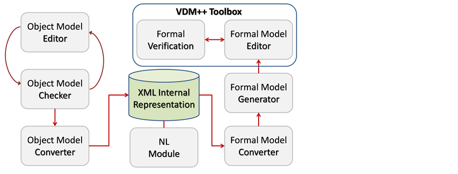
Figure 1. The FOTool architecture.
2) Study the semantics and identify the possible value or values for each of the UML model elements (i.e., class and activity diagram).
3) Study the semantics of VDM++ specifications.
4) Map the equivalent UML model element to the VDM++ model element.
5) If the mapping process is not possible due to inadequate UML models, the UML model elements are manipulated by using algorithm or augmented according to the properties of VDM++ construct.
Normally the syntax and semantics of VDM++ is richer than UML. In order to make a complete mapping we suggest that the UML models need to be augmented according to VDM++ construct. The detail mapping rules is described on next section.
3.1. Class Mapping
The mapping of UML class to VDM++ class is straight forward, as their syntax and semantics are similar. The UML class name is mapped directly to the VDM++ class name, the UML attributes properties is mapped to VDM++ instance variable definitions and the UML operation properties are mapped to the VDM++ operation definitions. However there is an augmentation to UML attributes values, we add attribute maximum value to enable the definition of invariant in VDM++ instance variable. The maximum value is only applicable to the attribute of type numeric. Therefore it is define as optional element in attribute properties. The UML class is defined by class name, attribute and operation. The properties of UML class are defined as:
class = (className, attribute, {attribute} operation, {operation})
attribute = visibility, name ‘:’ type [multiplicity, ordering]
‘:=’ initialValue, [maxValue] propertyString operation = visibility, name, ‘(’ parameterList ‘)’ ‘:’ returnTypepropertyString Before deriving the class mapping rules, we present the VDM++ class definitions, instance variable definitions and operation definition. The syntax for VDM++ class, instance variable definitions and operation definition are (CSK, 2005):
class’,identifier, [‘is subclass of’,identifier, {identifier};]
‘instance variables’
access, identifier, ‘:’, type, [‘:=’, expression]
| ‘inv’ expression, ‘;’
‘operations’
accessoperationName: argumentType‘==>’returnType operationName ‘(’ [patternList] ‘)’ ‘==’ operationBody
[‘pre’ expression ]
[‘post’ expression ] ;
‘end’ identifier;
The mapping of UML class properties to VDM++ class, instance variable definitions and operation definitions are defined as:
UMLClass |->VDM++Class = {className |-> identifier}
attribute |->instance variable = {visibility |-> access, name |-> identifier, type |-> type, initialValue |->expression}
3.2. Type Mapping
The type expression in UML is a language-dependent string that maps into a programming language data type. Hence, some of the types are not a direct mapping from UML attribute type to VDM++ instance variable type. The multiplicity and ordering properties in UML attribute are used to decide either the attribute is of type set or of type sequence in VDM++. This is only applicable when the multiplicity is more than one. If the multiplicity is more than one and ordering is “unordered” then the attribute is of type set, otherwise is of type sequence.
type |->{set of type | multiplicity ={2,…,n}and ordering = unordered} |
{sequence of type | multiplicity ={2,…,n}and ordering = ordered }
In FOTool the rules for set type and sequence type are implemented in its algorithm.
if multiplicity >1 then if ordering == true then type := seq of type else ifordering == false then
type := set of type If the attribute type in UML is String then it is mapped to the VDM++ type seq of charin VDM++ and if the attribute type in UML is of type class then it is mapped to the type composite in VDM++, and the integer type in UML can be directly map to integer in VDM++. In addition it also can be mapped into types nat and nat1 in VDM++. The mapping rules are derived based on the minimum value of UML attribute. For example if the attribute minimum value is zero, then it is mapped to type nat, and if the attribute minimum value is one, then the type will be mapped to nat1.
The typical type used for UML attribute type is defined as:
UMLType = {boolean, char, string, integer, double, class}
The VDM++ types are:
VDM++Type = {bool, nat, nat1, int, rat, real, char, quote, token, compound}
compound = {set, seq, map, product, composite, union, optional, function}
The mapping of UML types to VDM++ types are defined as UMLTypeToVDM++Type = {bool |->bool, char |-> char, string |->seq of charinteger |->int|{nat|minValue =0}|{nat1|minValue=1}double |->rat|real, class |->product|composite}
3.3. Invariant Mapping
The invariant values are the truth values for the identifier. If the UML attribute is of type char or type string the VDM++ invariant is defined by the set of VDM++ identifiers, if the UML attribute is of type boolean the VDM++ invariant is true or false, if the UML attribute is of type numeric (e.g., integer, double), then the VDM++ invariant is the allowable range from initial value to maximum value.
‘inv’
initialValue:=set of identifier | {type=char and type=string} or intialValue :=true|yes {type=Boolean} or
{initialValue, maxValue} |-> expression | {type=integer and type=double}
identifier = (plain letter | Greek letter){(plain letter | Greek letter) | digit | ‘ ’ ’ | ‘_’ }
expression = minValue‘<=’ identifier ‘and’ identifier ‘<=’ maxValue At this stage of development, FOTool has not yet integrated all the expressions define in the VDM++. In current implementation, the value for all attributes is defaulted according to its type, for example string and char the default value is null, boolean is true, integer is zero, and double is zero point zero. In order to ensure the valid model specifications, FOTool integrates the following rules to verify the attribute type and values:
The attribute value and the format correspond to the attribute data type. For example attribute of type double should consist of decimal point.
For attribute of type numeric, the range of attribute values is between the attribute’s initial value and attribute’s maximum value.
For attribute of type numeric, the attribute initial value should be smaller or equal to attribute maximum value. Attribute initial value is also used to denote attribute default or minimum value.
3.4. Association Mapping
In general, an association from a class ClassA to a class ClassB is mapped to VDM++ as follows. An instance variable attA of type ClassB is created inthe instance variables block of the ClassA as shown in Figure 2.
However, in practice there are different types of associations and to differentiate between them, and to iden-
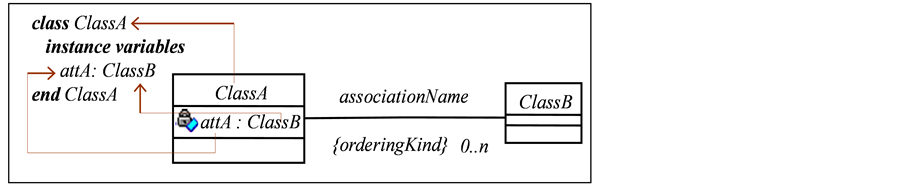
Figure 2. The VDM++ association relationships.
tify how they should be mapped to VDM++, the use of the ordered constraint in associations is vital. A boolean variable “orderingKind” is used to record if the pairs produced by the association from ClassA to ClassB are ordered or not. The rules defined in this part are adopted from Fitzgerald et al. [8]
If orderingKind is false and the multiplicity of the relationship is 1…1, then the type of the attribute attA exists once, and is mapped to an object reference type of type ClassB.
ClassClassA instance variables attA:ClassB;
endClassA If the orderingKind is true and the multiplicity of the relationship is 0…n, then the type of attribute attA, exists more than once and in order, and is mapped to a sequence of type ClassB.
ClassClassA instance variables attA: seq of ClassB := [];
endClassA If the orderingKind is false and the multiplicity of the relationship is 0…nthen the type of attribute attA, exist more than one and not in order, and is mapped to a set of type ClassB.
ClassClassA instance variables attA: set of ClassB := {};
3.5. Dynamic Model Mapping
The UML attributes and operations properties defined in the UML class specification are used to generate the operation signature of VDM++. This study focus on explicit operation definition as it clearly showing the dynamic behavior of the system via the computation algorithm. The VDM++ explicit operation definition has the form (CSK Corp, 2005) [6] :
operations
accessoperationName: argumentType==>returnType operationName([patternList] ) == operationBody
[preexpression ]
[postexpression];
The access, operationName, argumentType, returnType, patternList of VDM++ operation signature are generated directly from UML class operation visibility, operation Name, argument Type, return Type, and argumentName respectively. The VDM++ operation body, pre and post expressions are generated from the UML activity diagram which is used to define the UML operation algorithm. The UML class operation properties are not adequate for defining the operation algorithm, and therefore the conversion of the UML class operation into the operation’s body in VDM++ remains difficult. Therefore, the UML activity diagram is used to describe the class operation algorithm. The process flow and properties of activity diagrams are mapped to the body of the VDM++ operation. The body of the VDM++ operation is described by using a statement which is used as the basis to develop the algorithm. In the current development of FOTool, the block statement, call statement, return statement and if statement in VDM++ has been successfully generated from UML activity diagram. The output generated from FOTool has been successfully compiled by using VDM++ Toolbox version 8.1.
The blockstatement of VDM++ enables us to locally define variables by means of the declare statement in the body of the VDM++ operation and has the syntax (CSK Corp, 2005) [6] :
(dclidentifier: type [:= expression])
The identifier and type are mapped from UML class operation argument and its type. The expression is mapped from the initial value of UML operation argument. The operation argument is obtained from the class attribute, so that the operation’s argument properties are similar to the attribute properties.
The call statement of VDM++, calls an operation and returns the result of evaluating the operation and its syntax is (CSK Corp, 2005):
className.operationName(parameterList)
The target event name in UML transition specification denotes the target object for the event. Therefore the target event name is the appropriate property of transition specification to be map to className in the VDM++.
The send event name in UML transition specification represents the event to be sent to the next activity. This event depicts the name of the operation (or activity) to be executed by the next activity. Therefore the sent event name of transition specification is mapped to operationName in call statement of VDM++. The parameterList of VDM++ is mapped directly from the event argument in the UML transition specification.
The return statement of VDM++ returns the value of an operation and its syntax is (CSK Corp, 2005) [6] :
ReturnreturnValueor return The VDM++ return statement is generated if the UML operation return type is not equal to void. The VDM++ return value is mapped from the value of the event argument in the last transition of the activity diagram. The last transition depicts the final manipulation of the event argument.
If more than one event argument has the same type as the operation’s return type, FOTool will choose the correct return value based on the naming convention given to the operation’s name. For example operation getPrice() will return the value of the attribute price.
The VDM++ if statement, allows the choice of one from a number of expressions on the basis of the value of a particular expression. The if statement has the form (CSK Corp, 2005) [6] :
if(booleanExpression)
thenstatement elsestatement The BooleanExpression in VDM++ is defined by using binary expression. The guard condition defined in the transition specification isre-structured into the binary expression. This is to enable the guard condition in UML transition specification to be mapped into a Boolean expression in VDM++.
The flow of activity outgoing from decision construct of UML activity diagram determine the if-then-else structure in VDM++. This is carried out by comparing the guard condition against the decision. If the guard condition is equal to the decision then the statement that represent the true value will be executed otherwise the statement that represent false statement will be executed.
The pre-condition is a truth-valued expression before the activity or operation is evaluated. The post-condition is a truth-valued expression after the operation is evaluated (CSK Corp, 2005) [6] . The preand post-condition of VDM++ have the forms:
preexpression postexpression The preand post condition expression denote the binary expression which can be mapped to guard condition in the transition specification. We suggest that the initial guard condition, which is obtained from the first UML transition specification become the pre-condition of the VDM++ operation. Similarly the last guard condition, which is obtained from the last UML transition specification become the post-condition of the VDM++ operation.
4. FOTool Case Study: Indigenous Community Cultures
Indigenous communities in Sarawak have huge and complex beliefs and cultures related to their life, starting from when they were born until death. The relationships between beliefs and consequences in indigenous communities’ cultures and taboos are very abstract. Strong believers claim that the consequences happen because of the belief in taboos which relate to their cultures and daily activities. It is impossible to prove the logical or physical relationships between beliefs and its consequences. This research studies the culture of three indigenous communities namely Iban, Penan and Kadazan-dusun. The analysis of the heterogeneous cultures of these communities was carried and represented as object model as shown in Figure 3 which represent the typical model of indigenous community for three communities. The development of this model is not straight forward as it need to go through several refinement process in order to make sure it accommodate all beliefs, taboos and cultures of various ethnic groups of indigenous communities. As object model is easily expandable the other communities can be easily added in at the later stage.
The FOTool approach has been used to model the integration of indigenous community cultures and beliefs into genealogy software (Mit, E., et al., 2011). The FOTool process is started by developing use case diagram and class diagram. This phase is to get a general understanding on the features and requirements analysis of the genealogy software and class diagram is to identify the possible classes available. After use case diagram and class diagram is developed, the class operation is developed by using activity diagram. The formal specification is derived from the activity diagram specification to formalize the operations within the classes. The significant difference of this genealogy software is not like normal genealogy software which allows user to create family tree, but it integrates the history of particular individual (CV), the marriage relationship is integrate with the cultures and event, which happen before, during and after marriage ceremony, and it also allow the tracing of former wife or husband (i.e., divorce case).
Formalise the Indigenous Cultural Model
In FOTool approach the object model is transform into VDM++ formal representation. The mappings of static models (e.g., class attributes and operation signatures) to VDM++ specifications are straightforward [10] . However, the operation body or algorithm is very dynamic. This section give an example of formalism of dynamic model based on the rules as defined in FOTool. Take an example of class Omen (in Figure 3), the definitions of its operations in formal specifications is shown in Figure 4. In this example, the class definition, instance variables definition and operation signature are mapped directly from UML class, attribute and operation properties respectively, while the operation body is mapped based on dynamic model mapping rules as defines earlier. In this example, the “if-then-else”, “return” and “dcl” rules are used.
5. Discussion and Evaluation
Up to this stage of research FOTool has been used to model the integration of indigenous community cultures and beliefs into genealogy software, and in current development FOTool is deployed to model the fuzzy knowledge repository for indigenous community in Borneo [11] . The main important component of FOTool is the mapping rules that map the UML models to VDM++ formal model. There are several mapping rules that had
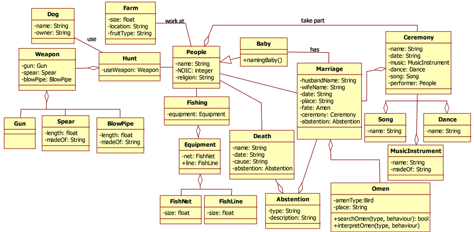
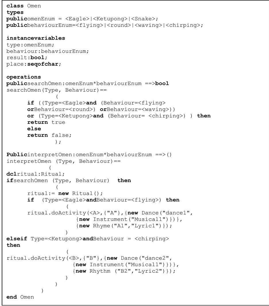
Figure 4. Formal specification of class Omen.
been defined in FOTool, such as static models mapping rules and dynamic models mapping rules. However, the biggest challenge to derive the mapping rules is to identify the semantics similarity between the model properties. Besides, there are also several challenges, such as the completeness and preciseness of model definition. Take an example of UML synchronization models in activity diagram, the same model can either represent “option” or “parallel” activities. Next is adequacy of the model, for example UML attribute properties are not sufficient to be directly mapped into VDM++ instance variable definitions, as it is lack of invariant definition. A more intelligent algorithm is required in conjunction with the mapping rules.
There are a number of improvements that need to be carried out on FOTool as there are huge syntax of VDM++ that need to be mapped from UML models. Simple prototype of FOTool has been developed, which consists of three main components, the object component, the formal component and the repository component. The object component is responsible for capturing and displaying UML element and its specification. The repository component is responsible for storing the UML specification in XML format, and the formal component is responsible for retrieving the XML specification, converting and displaying it in VDM++ formal specification. However, the VDM++ specification generated by using FOTool cannot be directly compiled by using VDM++ Toolbox. There exists the “blank” or “space” in the specification which is populated by symbols in between the syntax. This needs to be removed manually before it can be compiled successfully by using VDM++ Toolbox. In current development, the specification generated by using FOTool is not integrated with VDM++ Toolbox. In order to compile the output produced by FOTool by using VDM++ Toolbox, the output specification and file format need to comply with VDM++ Toolbox requirements.
6. Conclusion
The main objective of FOTool project is to enable users to create a rigourous software model from an easy and economic approach. This is carried out by developing mapping rules, which transform the easy model in this case UML models, into a more rigour model, in this case VDM++ formal specification. Therefore further verification of the model can be carried out by using formal methods tools. To date FOTool has been used to model the indigenous community marriage culture, and in our continuous work in modelling the indigenous community culture. FOTool is currently used to model the fuzzy knowledge repository for indigenous community, which later is expected to be used for generating logical explanation of knowledge in relation to modern life style. The biggest challenge to precisely model the remote community cultures in Sarawak is to elicit the reliable documentary sources or historical data, as almost all of it is not recorded. This is partly due to the accessibility to education, ICT technologies and the development of infrastructure was a bit late among the remote communities in Sarawak. Therefore, the possible source of historical data is through oral tradition, which can only be traced to several generations back. In addition, the results from this research suggested that FOTool is still lack of capability to transform all possible UML dynamic models to VDM++ specification. This is due to the incompleteness of its mapping rules. Further work needs to be done to integrate intelligent algorithm with the mapping rules where the semantics similarity may not be possible.
References
- Iglewski, M. and Müldnerü, T. (1997) Comparison of Formal Specification Methods and Object-Oriented Paradigms. Journal of Networks and Computer Applications, 20, 355-377.
- Warmer, J. and Kleppe, A. (1999) The Object Constraint Language Precise Modeling with UML. Addison-Wesley, Boston.
- Kim, S. and Carrington, D. (2000) An Integrated Framework with UML and Object-Z for Developing a Precise and Understandable Specification: The Light Control Case Study. 7th Asia-Pacific Software Engineering Conference, 240-248.
- Ledang, H. and Souquieres, J. (2002) Integration of UML and B Specification Techniques: Systematic Transformation from OCL Expressions into B. Proceedings of the Ninth Asia-Pasific Software Engineering Conference (APSEC’02), Australia, 4-6 December 2002, 495-503.
- Edwin, M. (2008) Developing VDM++ Operation Operations from UML Diagrams. PhD Thesis, University of Salford, Salford.
- CSK Corp (2005) VDMTools: The VDM++ Language, Ver6.8.1.
- OMG Group (2003) The OMG Unified Modeling Language Specification, Version 1.5. Technical Report, The OMG Group, Inc.
- Fitzgerald, J., Larsen, P.G., Mukherjee, P., Plat, N. and Verhoef, M. (2005) Validated Designs for Object-Oriented Systems. Springer-Verlag, Heidelberg.
- Yeo, A.W., Mit, E., Chiu, P.-C., Labadin, J. and Tan, P.-P. (2010) Cultural Modelling of Remote Communities. 3rd International Conference on Applied Human Factors and Ergonomics 2010 (AHFE 2010), Miami, 17-20 July 2010, 620-628.
- Mit, E., WaiShiang, C., Asyraf, M. and Hazlini, N. (2011) Integrate Cultures and Beliefs into Genealogy for Remote communities in Borneo. 2nd International Conference on User Science and Enginering (I-USEr 2011), Shah Alam, 29 November-01 December 2011, 222-227.
- Mit, E. and Ding, N.B. (2014) Framework of Indigenous Knowledge Representation. Proceedings of 5th International Conference on Intelligent Systems, Modelling and Simulation, Langkawi, 26-29 January 2014, 18-22.