Engineering
Vol. 3 No. 9 (2011) , Article ID: 7335 , 7 pages DOI:10.4236/eng.2011.39116
Effects of Gas Nitriding on the Mechanical and Corrosion Properties of SACM 645 Steel
140, Chung-Shan North Road, 3rd Sec., Chung-Shan District, Taipei City, Chinese Taipei
255, Hwa Kang Road, Yang Ming Shan, Taipei, Chinese Taipei
E-mail: g9607002@ms2.ttu.edu.tw, lhchiu@ttu.edu.tw, hchang@faculty.pccu.edu.tw
Received June 23, 2011; revised August 4, 2011; accepted August 22, 2011
Keywords: Nitriding, Steel, Wear, Fatigue
ABSTRACT
The effects of the nitrided case produced by gas nitriding processes on the mechanical and corrosion resistance properties of the JIS SACM 645 steel were studied in this paper. JIS SACM 645 steel specimens with different substrate hardness were gas nitrided at 530˚C for various nitriding durations. Nitrided specimens were characterized by means of optical and scanning electron microscopy, X-ray diffraction, glow discharge optical spectrometry, microhardness profiling, wear test, torsion mode fatigue test as well as electrochemical corrosion test in an aerated 3.5% NaCl solution. The surface hardness values of the nitrided specimens with Fe3N and Fe4N phases precipitated in the case layer were observed higher than 1000 HV0.1. Mass loss measurement of the wear test showed increases of wear resistance of the nitrided specimens, and the mass losses of the specimens were strongly influenced by nitriding durations. Electrochemical measurements showed that corrosion current density of the specimens was significantly decreased after nitriding and the corrosion potential was shifted to the noble direction as the increase of the nitriding durations. The fatigue limit of the specimen nitrided for 96 h rose 44% to 600 MPa in exceeding the untreated specimen in this study.
1. Introduction
The positive effects of surface treatments like nitriding on the fatigue and wear properties of structural steel have been known for several decades. Tools and components used in the severe environment must have excellent fatigue resistance and wear resistance. Consequently, the structural steel of those components should be always surface modified to provide these needed properties. The surfaces of these components are required to attain high hardness values to resist wear, and the inner cores still need to have high toughness strength [1,2]. Therefore, various methods, such as nitriding, carburizing, ceramic coating and thermal chemical treatments, have been devised to improve the surface mechanical properties of the components [3-5]. Among those surface treatment processes, the gas nitriding methods have been used extensively to enhance the mechanical properties of steel components [5-13]. During the gas nitriding treatment, nitrogen, which is provided by the catalytic dissociation of ammonia, diffuses through the steel surface to form a concentration gradient as well as nitride precipitates in the nitriding case. The solid solution of nitrogen in the metal substrate and the nitride precipitates are responsible for the increase of hardness and compressive macrostresses in the diffusion layer [7].
The fatigue characteristics of nitrided SACM 645 steel were investigated by Bell et al. [5]. According to the nitriding condition and notch shape, the improvement of the fatigue characteristics of the notched specimens was more effective than unnotched specimens. Peng [11] investigated ammonia-gas nitriding on AISI 304 austenitic stainless steel at temperatures higher than 800˚C. The result from Peng showed that a metas phase named ‘S-phase’ or ‘γN-phase’ (expanded austenite) was formed at such high temperatures due to a sufficiently high nitriding potential of ammonia gas. Ashrafizadeh [12] further concluded that the compound layer had no significant influence on fatigue limits, but instead it was the diffusion layer which had the dominating effect on the fatigue behavior of nitrided specimens. Pellizzari [13] also reported that the hard porous compound layer was brittle and favored crack initiation to decrease the thermal fatigue resistance. As the reasons for the improvement in fatigue limit have not been known, there are also lack of studies on the quantitative relations between process parameters of the surface treatment and the fatigue limits. The aim of present study is to investigate the effects of different gas nitriding parameters on the mechanical and corrosion properties of the SACM 645 steel, as well as the effect of the substrate hardness on the wear, fatigue and corrosion properties of nitrided SACM 645 steel specimens.
2. Experimental Procedures
The chemical composition (wt%) of the specimen analyzed by a glow-discharge optical emission spectroscope (LECO, GDOES-750) is listed in Table 1. The specimens were quenched and tempered to the substrate hardness of 30, 35 and 40 HRC before nitriding. The surfaces of specimens were fine-ground using abrasive papers to a 1200-grit finish and cleaned with acetone solution in an ultrasonic cleaner. Treatments were carried out in a gas nitriding furnace and the process parameters used in the nitriding of steel was set at 530˚C for 12 h, 24 h, 48 h, 96 h. The chamber atmosphere was filled with NH3 gas at a flow rate of 0.6 ml/min. To classify the specimens undergone various treatment conditions, specimen abbreviations are coded in Table 2.
The cross-sectional microstructure of the specimens was revealed using a chemical solution of 95 ml alcohol +5 ml HNO3, and was observed on an optical microscope (Nikon OPTIPHOT-100). The fracture surface of the nitrided specimen through fatigue test, conducted on a torsion mode machine with 3600 rpm at room temperature, was examined on a JEOL JSM-5600 scanning electron microscope (SEM). The phases precipitated in the case layer of the nitrided specimen were characterized on an X-ray diffractometer with a Cu-Kα radiation source over the 2θ range from 20˚ to 120˚. Microhardness was measured by using a Vickers microhardness tester with the applied load of 100 g. The wear resistance of the nitrided specimens was investigated on a non-lubricated block-on-roller tester. The counter-roller on the block-
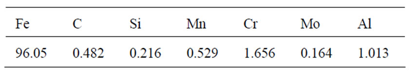
Table 1. Chemical composition of the SACM 645 steel (wt%).
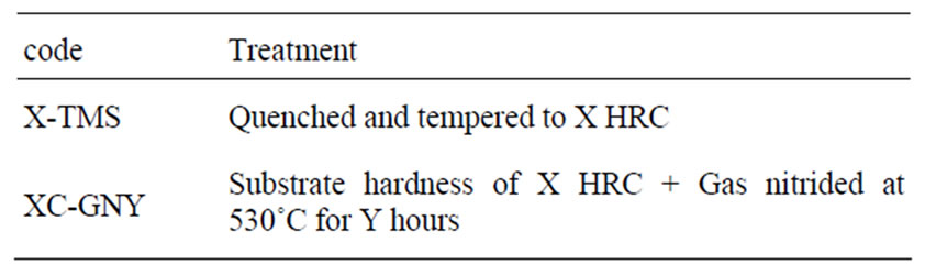
Table 2. Codes of specimens and treatments.
on-roller tester was made of JIS SKS3 (AISI O1) tool steel with hardness of 62HRC. A normal load of 95.9 N was applied on the roller and the counter-roller was rotated at 180 rpm. Fatigue tests were carried out in torsion mode at a stress reversal frequency of 3600 rpm. The fatigue limit was determined by the so-called staircase method and was defined at 107 cycles. The corrosion behavior was evaluated by electrochemical analysis. Potentiodynamic polarization measurements were carried out using a conventional three-electrode cell housing a working electrode, a platinum counter electrode, and a saturated silver chloride (SSC) reference electrode in a 3.5% NaCl solution at 25˚C. The potentiodynamic scan was recorded starting from corrosion potential of -0.6 V to 1.0 V in a potential scan rate of 1 mV/s.
3. Results and Discussion
3.1. Microstructures
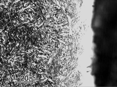
Figure 1 shows the cross sectional micrographs of nitrided specimens produced by the gas nitriding treatment at 530˚C of different time durations. The specimens were mechanically fine-ground and polished, followed by etching in a 5% Nital solution. A slightly etched outer white compound layer of approximately 15 mm was observed and were soundly bonded with the nitrogen diffusion layer underneath. Moreover, compound layer without voids and porosities was obtained for all nitrided specimens with the substrate hardness of 30 HRC, even as the nitriding duration prolonging to 96 h. In comparison, the compound layer of specimen with substrate hardness of 40 HRC exhibited a non-homogeneous structure as shown in Figure 1(e). As seen in the diffusion zone, nitrogen was dissolved in the tempered martensite substrate at 530˚C and nitride precipitates were observed due to the decrease of solubility of nitrogen [12].
Measurement of averaged case thickness was carried out by taking measurements at 5 different positions on the micrograph in Figure 1. Images of Figure 1(a) to 1(d) showed the thickness of white layers was about 15 ± 5 μm and the diffusion layer thickness was about 300, 550 μm, 800 μm and 1100 μm, respectively. The thickness of diffusion layers was evidently increased with prolonging nitriding duration. The case thickness was strongly correlated to the microhardness profiles of the nitrided specimens as shown in Figure 2.
3.2. Microhardness
The cross sectional hardness profiles of nitrided specimens in given conditions are shown in Figure 2. All
 (a)
(a)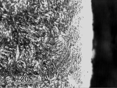 (b)
(b)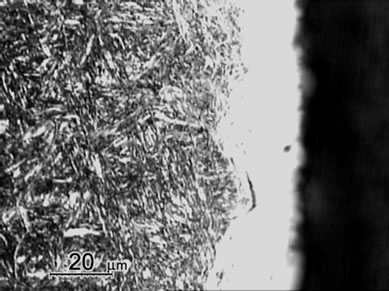 (c)
(c)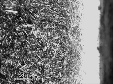 (d)
(d)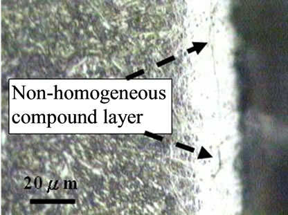 (e)
(e)
Figure 1. Micrographs of SACM 645 specimens nitrided at given processing conditions, (a) 30C-GN12, (b) 30C-GN24, (c) 30C-GN48, (d) 30C-GN96 and (e) 40C-GN48.

Figure 2. Microhardness profiles of specimens nitrided at given conditions.
specimens showed high surface microhardness values to about 1100 HV0.1. Based on the CNS 14288-G2272 standard [14], the effective case depth of the nitrided specimen was calculated as the case hardness value reaches the substrate hardness plus 50 HV. The effective case depth of the specimens in Figure 2 as a function of the nitriding duration was shown in Figure 3. As can be
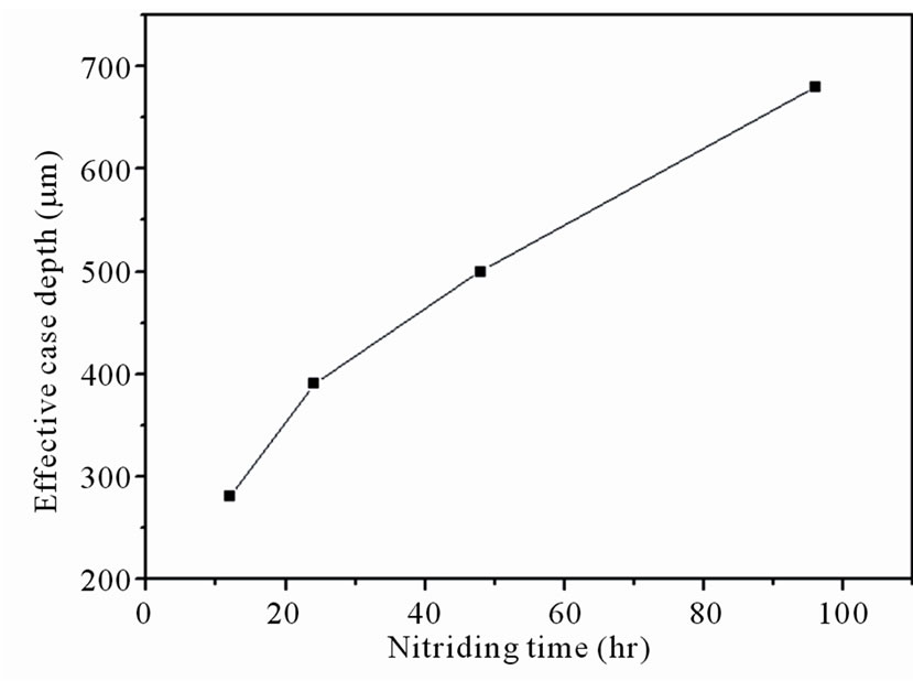
Figure 3. Effective case depth as a function of the nitriding duration.
seen, the effective case depth increased as the increase of the nitriding duration.
It can be observed in Figure 2 that hardness value monotonically drops from the case surface to the substrate. Due to the hardening and trapping effects of the ε-phase (Fe3N) and γ’-phase (Fe4N) in the nitrided layer, hardness profiles of the diffusion layer decreased exponentially from the surface. The observed result was in agreement with Suh et al. [2]. A considerable increase in the microhardness of the diffusion zone can be achieved by increasing the amount of supersaturated dissolved nitrogen (solid solution strengthening) [12]. As prolonging the nitriding duration, the effective case depth of specimen treated for 96 h increased to 690 μm.
3.3. XRD Examinations
The X-ray diffraction (XRD) patterns at distinct case depths of 30C-GN48 specimen nitrided at 530˚C for 48 h are shown in Figure 4. The figure depicted the presence of Fe2O3 peaks in the outer case surface. In order to identify the constituents at distinct case depths, the nitrided specimen was carefully sliced off layer by layer of every 30 μm towards the substrate to expose the white compound layer and diffusion layer of the nitrided case.
At case depth of 30 μm, the presence of dominant peaks of the ε-phase (Fe3N) and minor peaks of the γ’-phase (Fe4N) were detected. At depth of 110 μm and 200 μm from surface, the presence of broaden peaks of martensite phase showed the trapping effect of nitrogen atoms; it was worth noting that peaks of ε-phase (Fe3N) and γ’-phase (Fe4N) were not spotted. At the substrate, the dominant peaks in the XRD pattern were the tempered martensite phase. Other nitrided specimens of different nitriding parameters have depicted similar XRD patterns as those shown in Figure 4.
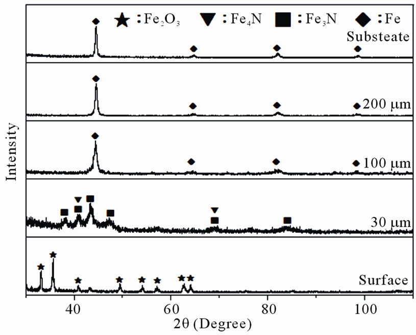
Figure 4. XRD patterns of substrate and gas nitrided layers at 530˚C × 48h.
3.4. Wear Behavior
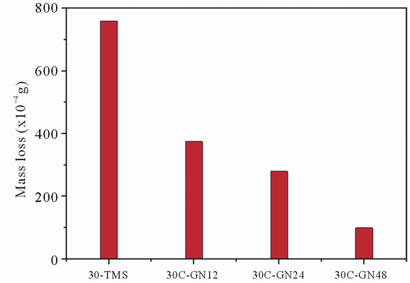
Figure 5(a) shows the effect of nitriding duration on the cumulative wear mass loss of the nitrided specimens. The nitrided specimens exhibited only small amount of cumulative mass losses (in the order of 10–2 g) as a result of the hard compound layers of the nitrided cases. The cumulative mass loss was decreased as the increase of the nitriding duration. The amount of cumulative mass loss of the specimen nitrided for 48 h was only 0.01 g. The wear resistance after nitriding was significantly improved with increase of the nitriding duration. Figure 5(b) shows the effect of different substrate hardness values on the cumulative wear mass losses of the nitrided specimens. It was observed that the increases of the substrate hardness values of the specimens nitrided for 48 h resulted in the decreases of the cumulative mass loss.
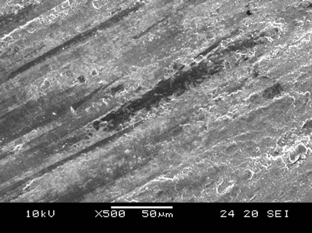
Scanning electron microscope (SEM) micrographs of the wear tracks for both the untreated and nitrided surfaces after wear testing at a load of 95.9 N for 3 h are shown in Figure 6. On non-nitrided tempered martensitic specimen (30-TMS), severe abrasive wear was observed (Figure 6(a)), whereas the nitrided specimen (30C-GN48) revealed very mild abrasive and adhesive wear tracks on the surface as shown in Figure 6(b).
3.5. Fatigue Behavior
Figure 7 shows the fatigue characteristics of untreated and gas nitrided specimens under different nitriding conditions. Fatigue test was carried out in torsion mode at a stress reversal frequency of 3600 rpm. The fatigue limit of the S-N curves for all testing specimens was defined at 1.0 × 10⁷ cycles without fatigue failure. The fatigue limit of the non-nitrided specimen (30-TMS) was 416
 (a)
(a)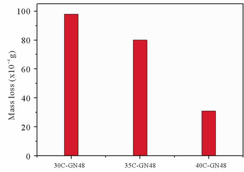 (b)
(b)
Figure 5. Mass losses of specimens at given wear test condition for (a) various nitriding durations, and (b) various substrate hardness values.
MPa, whereas the fatigue limits of the 30C-GN12, 30C-GN24, 30C-GN48 and 30C-GN96 nitrided specimens were 539, 574, 590 and 600 MPa, respectively. The increase of fatigue limit of the 30C-GN96 specimen was 44.2% compared to the tempered martensitic substrate (30-TMS) specimen observed. Suh et al. [2] reported the rotary bending fatigue characteristics of nitrided SACM 645 steel and found that the fatigue crack was initiated beneath the nitrided layer by residual compressive stress on the surface. They indicated that the crack initiation was hindered by the nitriding layer, while the finding was similar to the work done by Buchhagen and Bell [15]. As shown in previous work [16], the fatigue limit of the specimen with substrate harness value of 35 HRC nitrided for 48 h was reported at a value of 632 MPa, indicating that fatigue limit was affected by the substrate hardness.
Fatigue fracture surfaces of nitrided and non-nitrided specimens after fatigue test were further analyzed using SEM. Fractographic analysis revealed that the fatigue
 (a)
(a)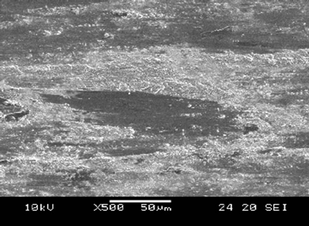 (b)
(b)
Figure 6. SEM surface morphology of worn specimens undergone tests at 95.9 N for 3 h, (a) 30-TMS, (b) 30C-GN48.
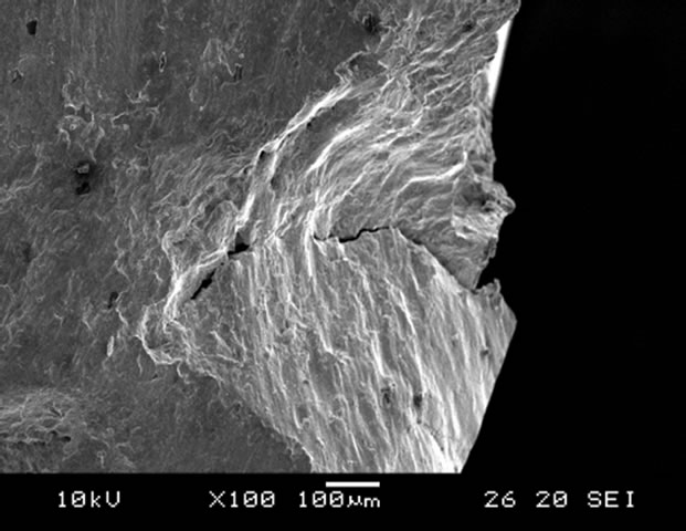
crack in the non-nitrided specimen (30-TMS) was initiated at the surface. A typical surface fatigue initiation site is shown in Figure 8(a). In contrast, of the specimens nitrided for 48 h, the fatigue cracks were initiated beneath the nitrided layer close to the substrate-diffusion layer interface as shown in Figure 8(b). Similar result was reported by Hussain [17]. As a result, the fatigue
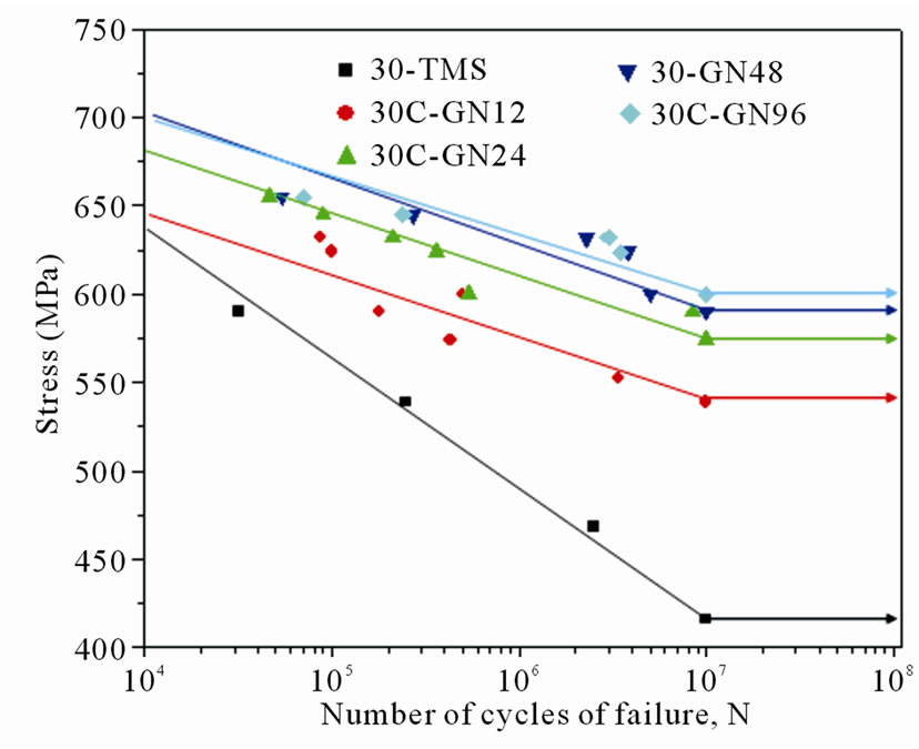
Figure 7. S-N curves of non-nitrided and gas nitrided specimens at given conditions.
 (a)
(a)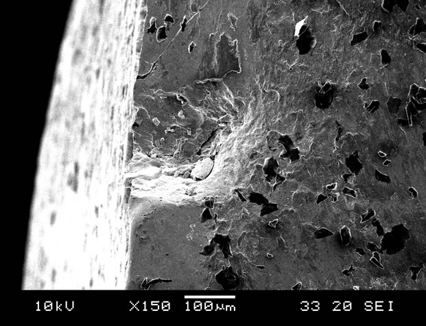 (b)
(b)
Figure 8. Fracture surface of fatigue specimen after fatigue test for (a) 30-TMS and (b) 30C-GN48.
limit was improved by gas nitriding, and the fatigue limits increased with increasing nitriding duration.
3.6. Corrosion Behavior
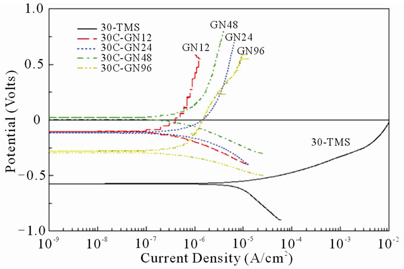
The polarization curves of non-nitrided and nitrided specimens treated with different nitriding durations are shown in Figure 9(a). The polarization curves in Figure 9(a) indicated that the non-nitrided specimen did not passivate and endured a continuous dissolution with the corrosion current density (Icorr) of 1.0 × 10⁻⁵ A/cm2. The corrosion potential (Ecorr) of the nitrided specimens was shifted to the noble direction as the increases of the nitriding duration. The corrosion current density (Icorr) was significantly decreased after nitriding compared to the non-nitrided substrate, which indicated that the nitrided case impeded the anodic dissolution resulted in a very low corrosion current. The corrosion current densities (Icorr) of all nitrided specimens were fallen in the range between 3.0 × 10⁻⁷ and 6.5 × 10⁻⁷ A/cm2.
Figure 9(b) shows the polarization curves of nonnitrided specimen and specimens nitrided for 48 h with different substrate hardness values. A noteworthy shift of the corrosion potentials to more positive values was observed as the substrate hardness of the nitrided specimens decreased. The polarization curves in Figure 9(b) depicted that the corrosion potentials (Ecorr) of 30CGN48, 35C-GN48, 40C-GN48 specimen were about 100 mV, –150 mV and –300 mV. The shift of the corrosion potential (Ecorr) of nitrided specimens with different substrate hardness may be caused by the non-homogeneous compound layer structure such as cracks in the surface layer. Basso et al. [18] suggested that the porosities or cracks on the compound layer were pathways to connect the 3.5% NaCl solution and substrate through the nitrided case. The corrosion current density (Icorr) of the nitrided specimen with substrate hardness of 40 HRC, close to Icorr of 30-TMS specimen, was about an order higher than the nitrided specimen with substrate hardness of 30 HRC. Consequently, the corrosion resistance was evidently influenced by the substrate hardness values.
4. Conclusions
From the X-ray diffraction patterns, Fe2O3 peaks were detected on the case surface, and the ε-phase (Fe3N) and
 (a)
(a)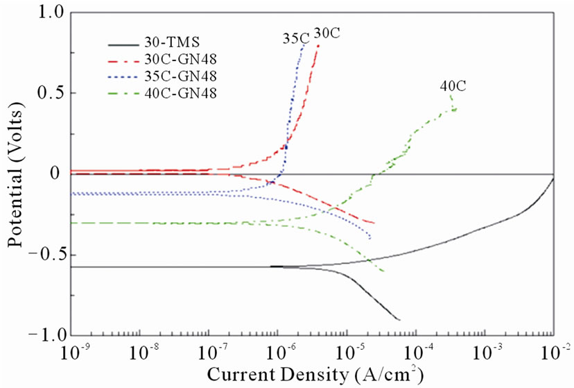 (b)
(b)
Figure 9. Polarization curves of non-nitrided and nitrided at 530˚C specimens for (a) various nitriding durations and (b) substrate hardness values.
minor peaks of the γ’-phase (Fe4N) were appeared at the nitrided case depth of 30 μm. The surface hardness of the nitrided specimens reached values in the range between 1000 HV0.1– 1100 HV0.1. Wear test data indicated that the mass loss of JIS SACM 645 steel was greatly improved by nitriding processes and the wear resistance of the nitrided specimens was significantly improved by extending nitriding duration.
The fatigue limit of the SACM450 steel was greatly improved by nitriding process. It was observed that the fatigue crack of the nitrided specimen was initiated beneath the nitrided layer. With the increase of the diffusion layer thickness, the fatigue limit increased by prolonging nitriding duration. The fatigue limit of 30C-GN96 specimen was 600 MPa which was a 44.2% increase over the 30-TMS specimen in this study.
According to electrochemical measurements, the corrosion potential of nitrided specimen was shifted to the noble direction as the increases of the nitriding duration. The corrosion current densities of all nitrided specimens, in the range of 3.0 × 10⁻⁷ ~ 6.5 × 10⁻⁷ A/cm2, were at least an order lower than that of the non-nitrided substrate, 1.0 × 10⁻⁵ A/cm2. As a result, the corrosion resistance was significantly improved by gas nitriding process.
5. REFERENCES
- C. M. Suh and H. K. Jang, “Effects of Surface Hardening and Residual Stress on the Fatigue Characteristics of Nitrided SACM 645 Steel,” International Journal of Modern Physics B, Vol. 17, No. 8-9, 2003, pp. 1633-1639.
- C. M. Suh, J. K. Hwang, K. S. Son and H. K. Jang, “Fatigue Characteristics of Nitrided SACM 645 According to the Nitriding Condition and Notch,” Materials Science and Engineering A, Vol. 392, No. 1-2, 2005, pp. 31-37. doi:10.1016/j.msea.2004.07.066
- J. Baranowskaa and S. E. Franklin, “Characterization of Gas-Nitrided Austenitic Steel with an Amorphous/ Nanocry-Stalline Top Layer,” Wear, Vol. 264, No. 9-10, 2008, pp. 899-903.
- S. Abisset, F. Maury, R. Feurer, M. Ducarroir, M. Nadal and M. Andrieux, “Gas and Plasma Nitriding Pretreatments of Steel Substrates before CVD Growth of Hard Refractory Coatings,” Thin Solid Films, Vol. 315, No. 1-2, 1998, pp. 179-185. doi:10.1016/S0040-6090(97)00787-6
- C. Allen, C. X. Li, T. Bell and Y. Sun, “The Effect of Fretting on the Fatigue Behaviour of Plasma Nitrided Stainless Steels,” Wear, Vol. 254, No. 11, 2003, pp. 1106-1112.
- K. Genel, M. Demirkol and M. Capa, “Effect of Ion Nitriding on Fatigue Behaviour of AISI 4140 Steel,” Materials Science and Engineering A, Vol. 279, No. 1-2, 2000, pp. 207-216. doi:10.1016/S0921-5093(99)00689-9
- N. Limodin and Y. Verreman, “Fatigue Strength Improvement of a 4140 Steel by Gas Nitriding: Influence of Notch Severity,” Materials Science and Engineering A, Vols. 435-436, 2006, pp. 460-467. doi:10.1016/j.msea.2006.07.034
- A. Celik and S. Karadeniz, “Improvement of the Fatigue Strength of AISI 4140 Steel by an Ion Nitriding Process,” Surface and Coatings Technology, Vol. 72, No. 3, 1995, pp. 169-173. doi:10.1016/0257-8972(94)02348-4
- J. H. Sung, J. H. Kong, D. K. Yoo, H. Y. On, D. J. Lee and H. W. Lee, “Phase Changes of the AISI 430 Ferritic Stainless Steels after High-Temperature Gas Nitriding and Tempering Heat Treatment,” Materials Science and Engineering A, Vol. 489, 2008, pp. 38-43.
- H. W. Lee, J. H. Kong, D. J. Lee, H. Y. On and J. H. Sung, “A Study on High Temperature Gas Nitriding and Tempering Heat Treatment in 17Cr–1Ni–0.5C,” Materials & Design, Vol. 30, No. 5, 2009, pp. 1691-1696.
- D. Q. Peng, T. H. Kim, J. H. Chung and J. K. Park, “Development of Nitride-Layer of AISI 304 Austenitic Stainless Steel during High-Temperature Ammonia Gas-Nitriding,” Applied Surface Science, Vol. 256, No. 24, 2010, pp. 7522-7529. doi:10.1016/j.apsusc.2010.05.100
- F. Ashrafizadeh, “Influence of Plasma and Gas Nitriding on Fatigue Resistance of Plain Carbon (Ck45) Steel,” Surface and Coatings Technology, Vols. 174-175, 2003, pp. 1196-1200. doi:10.1016/S0257-8972(03)00460-2
- M. Pellizzari, A. Molinari and G. Straffelini, “Thermal Fatigue Resistance of GAS and Plasma Nitrided 41CrAlMo7 Steel,” Materials Science and Engineering, Vol. A352, 2003, pp. 186-194.
- CNS: 14288-G2272, 2006, 1-6.
- P. Buchhagen and T. Bell, “Simulation of the Residual Stress Development in the Diffusion Layer of Low Alloy Plasma Nitrided Steels,” Computational Materials Science, Vol. 7, No. 1-2, 1996, pp. 228-234. doi:10.1016/S0927-0256(96)00085-7
- S. H. Yeh, L. H. Chiu and H. Chang, “Influence of Vacuum Heat Treatment an Salt-Bath Nitrocarburization on the Corrosion Behavior of JIS SKD61 and DH31S Hot Work Steels,” Advanced Materials Research, Vol. 47-50, 2008, pp. 686-689.
- K. Hussain, A. Tauqir, A. Haq and A. Q. Khan, “Influence of Gas Nitriding on Fatigue Resistance of Maraging Steel,” International journal of fatigue, Vol. 21, No. 2, 1999, pp. 163-168. doi:10.1016/S0142-1123(98)00063-2
- R. L. O. Basso, R. J. Candal, C. A. Figueroa, D. Wisnivesky and F. Alvarez, “Influence of Microstructure on the Corrosion Behavior of Nitrocarburized AISI H13 Tool Steel Obtained by Pulsed DC Plasma,” Surface and Coatings Technology, Vol. 203, No. 10-11, 2009, pp. 1293-1297. doi:10.1016/j.surfcoat.2008.10.006