Engineering
Vol. 3 No. 6 (2011) , Article ID: 5706 , 4 pages DOI:10.4236/eng.2011.36076
Microscopic Observation of Nuclear Track Pores in Polymeric Membranes
Department of Applied Physics, Faculty of Technology and Engineering, The M. S. University of Baroda, Vadodara, India
E-mail: sarnavee@gmail.com
Received March 9, 2011; revised May 5, 2011; accepted May 15, 2011
Keywords: Nuclear track pore, polymer membrane, ion irradiation, chemical etching
ABSTRACT
Nuclear track pores were develop and observed in polycarbonate and LR-115 membranes. The polymer membranes were irradiated by swift heavy ions (SHI) and etched chemically. The stopping range of heavy ion is larger than the thickness of the membrane. The fluence of ions was changes from 103 to 107 ions-cm−2. The etching time was increased till pore size reaches up to micron range. The etching conditions were set to develop the porous tracks. The tracks are revealed under optical microscope as the size reaches up to micron or sub-micron size. The size was measured using standard electron diffraction grid. Results show that the porous tracks having average size of 2.4 micron can be developed in polycarbonate, while 5 - 10 micron porous tracks can be developed in LR-115.
1. Introduction
Polymer membranes are being used for nuclear track detection since last few years. Various methods were employed to develop nuclear tracks in polymer membranes. Out of them ion track technology is one of the efficient tool to generate tracks. Nuclear tracks were developed and studied in metals, semiconductors and insulators. In mica tracks are quite visible under high-resolution microscope [1]. Most of polymers are insulator and the energy loss by a charged particle may kick off cascade process that results the formation of new species and finally loosely bound material remains left. This loosely bound material has distinct properties and known as nuclear tracks. The chemical etching creates pores in loosely bound material in such a way that tracks are converted into porous structure [2].
The modifications of polymeric membranes have potential applications i.e. gas permeation and gas separation. However, the modification includes ion irradiation [3] or by depositing a metallic layer on membrane surface [4]. The idea besides present work is to develop a micro-filter using ion irradiation and subsequent etching because the tracks can be enlarge by employing chemical etching after irradiation of polymer membrane. The size of tracks reaches up to certain micron depending on the etching environment as well as on the irradiation parameters. The pore diameter can be achieved up to 5 micron under special etching conditions [5]. So the tracks produced during irradiation now become pores and they are quite visible under optical microscope. The only condition associated with the ion beam is that the stopping range of incident ion should be more than the thickness of the polymer membrane. The etched pits due to irradiation in OHP film have been observed by Basu [6].
In present proposed work, the polymer membranes of several microns thick were irradiated by heavy energetic ions and were undergo the post irradiation etching. The incident ion was chosen such that it allowed to creating the porous tracks. The nuclear track pores were visualized under optical microscope when it reaches up to sub micron scale.
2. Experimental
2.1. The Materials
Polycarbonate and LR-115 were used for the present study. Polycarbonate was procured from National Chemical Laboratory, Pune and LR-115 was commercially available. The LR-115 has 12 μm thick cellulose nitrate film on 100 μm thick poly(etheleneterepthlate) substrate. The structure of LR-115 is shown in Figure 1.
2.2. Irradiation
Swift heavy ion (SHI) irradiation was performed at Inter University Accelerator Centre (Formerly, Nuclear Science Center), New Delhi. The polycarbonate membrane was irradiated by carbon ion beam of 60 MeV, while LR-115 samples were irradiated by silicon ion beam of 100 MeV under the vacuum environment of 10−6 torr. The energy of incident ion was sufficient to penetrate the polymer membrane for both the cases.
Here, cellulose nitrate film of LR-115 is exposed by energetic ion beam. The thickness of target material was less than the stopping range of incident ion. The fluence was maintained up to 107 ions-cm−2 for polycarbonate. The dose was selected to avoid the overlapping of nuclear track pores.
The LR-115 samples were mounted at different angles 12˚, 60˚, 120˚ with respect to incident beam as shown in Figure 2. The beam current was constant during irradiation. The beam was scattered by a gold foil in vacuum
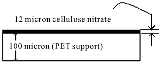
Figure 1. The structure of LR-115.
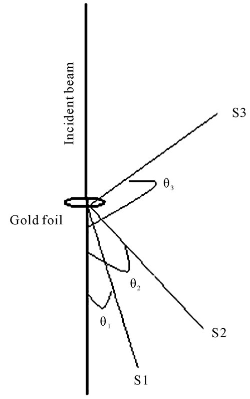
Figure 2. Different samples mounted at S1, S2 and S3 positions makes θ1, θ2, θ3 angle respectively with the incident beam in evacuated scattering chamber.
chamber, consequently the doses falls on different samples can be followed by Rutherford’s formula. The actual dose was calculated by surface barrier detector kept at 24˚ and relative doses were estimated. In an experiment the initial dose at 12˚ and 120˚ was 107 and 103 ion-cm−2 respectively.
2.3. Chemical Etching
The irradiated polymer samples were etched chemically at standard etching conditions. For polycarbonate, 6N NaOH solution at 60˚C was used, while for LR-115, 2.5 N NaOH at 60˚C was used. Initially, the etching was performed for 10 seconds. The step etching process was continuing till full track etching was achieved. s
2.4. Optical Microscopy
The optical micrographs were taken using LABOMED (10x) microscope. The electron microscopic grid was used as reference for scaling the micrographs as shown in Figure 3.
It was a circular grid having 3 mm of diameter and there were one thousand very small squares in 7.06 mm2 area. The side of a small square can be magnified under microscope at various magnifications, i.e. 10, 40 and 100. The micrographs were stored in computer through standard software (PixelView). The various micrographs were taken at 10x magnification. The scale on other micrographs can be determined on comparing with electron microscopic grid and confirmed by filler micrometer attached with microscope.
3. Results and Discussion
The irradiated membranes were etched for less etching time is used for gas filters, through that a particular gas
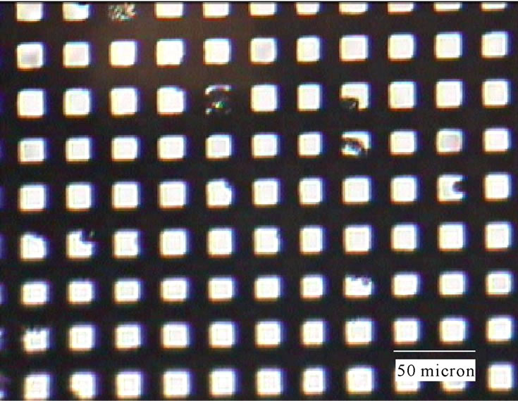
Figure 3. Micrograph of electron diffraction grid (10x).
passes and the others were rejected, so the tracks have several nm size [7]. These tracks can be enlarged by employing extended chemical etching. The dependence of scattered ions with angle of incidence (r) is shown in Figure 4.
To observe the tracks it is required to enlarge them by etching, and they are quite visible under microscope only when the size reaches to micron scale. On higher etching the tracks become pores. The size of pores was optimized by comparing it with electron diffraction grid. Figure 3 shows the micrograph of electron diffraction grid (10x View). Both the polycarbonate and LR-115 are sensitive materials and are being used for solid state nuclear track detectors (SSNTDs).
3.1. Nuclear Track Pores in Polycarbonate
The optical micrograph of irradiated and etched polycarbonate is shown in Figure 5. Nuclear track pores are visualized only after extended chemical etching.
The micrograph as shown in Figure 5 was compared with Figure 3 and the average pore size has been found to 2.4 micron. The pore size increases with increasing etching time and pores of 2.4 micron were observed for 35 minutes of etching in polycarbonate. Optical microscopy gives the porous structure only on higher etching; however the Atomic Force Microscopy is an efficient tool to investigate the porous tracks at relatively lower etching [8]. It was observed that the size of tracks varies with energy loss during irradiation as well as etching conditions. The pore density is found to be 107 /cm2 that indicate the non-appearance of overlapping of the tracks.
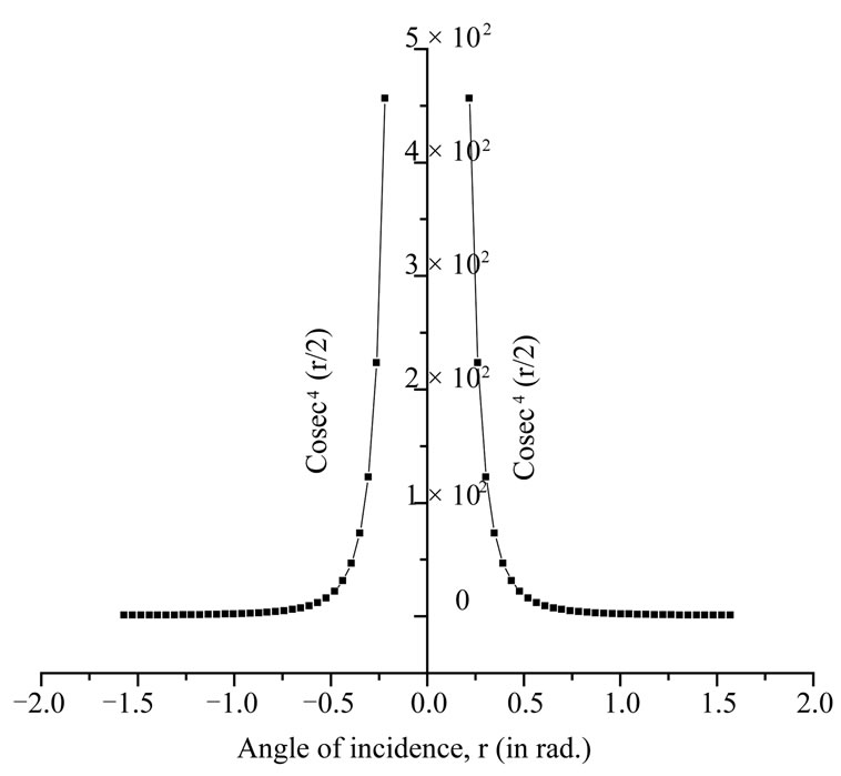
Figure 4. The graph of cosec4 (r/2) versus angle of incidence (r).
3.2. Nuclear Track Pores in LR-115
Since, LR-115 is highly sensible then polycarbonate, hence it require less etching time to develop the nuclear track pore. It is found that the required etching time for enlarged pores in LR-115 is only 2 - 3 minutes. The optical micrographs of porous structure in LR-115 are shown in Figure 6, 7 and 8 respectively. These samples were mounted at different angles. It was observed that the overlapping of nuclear track pores starts immediately due to etching as shown in Figure 6.
Overlapping starts at higher doses, while at lower doses the individual track pores can be identified and marked as shown in Figure 7 and Figure 8. It was observed that the average pore of nuclear tracks reaches up to 5 micron in 2 - 3 minutes of etching.
It was also observed that the distribution of track pores was inhomogeneous; it may be due to some statistical fluctuations in dose distribution during irradiation as
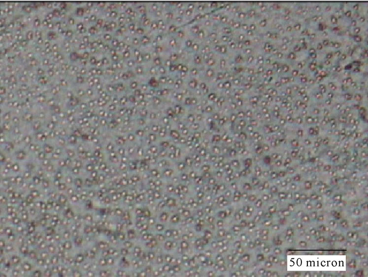
Figure 5. Nuclear Track Pores in polycarbonate track etched membrane (400 × 300 μm).
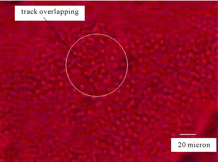
Figure 6. Optical micrograph of irradiated and etched LR-115 (260 × 200 μm).
shown in Figure 7 and Figure 8.
4. Conclusions
It is concluded from the above study that nuclear track pores can be developed in ion irradiated polymer membrane. It is observed that the LR-115 is more sensible then the polycarbonate material. This may be due to the bisphenol-A backbone structure of polycarbonate and it provides the relatively high strength against the chemical etching. The porous structure was visible under optical microscope only after extensive chemical etching. However, the size of pore depends on the type of material and the irradiation conditions.
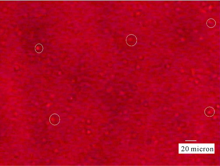
Figure 7. Optical micrograph of irradiated and etched LR-115 (400 × 300 μm).
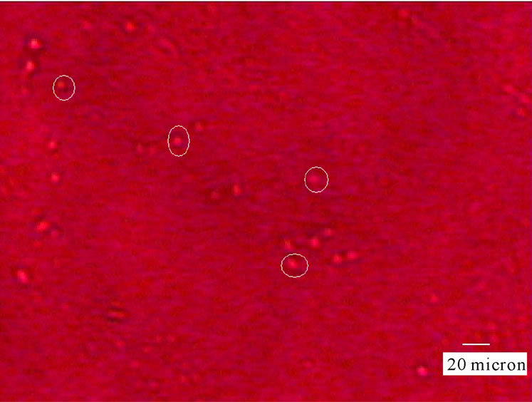
Figure 8. Optical micrograph of irradiated and etched LR-115 (400 × 300 μm).
5. Acknowledgements
The author is thankful to Department of Science and Technology, New Delhi for providing financial support under FAST TRACK scheme (PS-32/2006). The author is grateful to Prof. Y. K. Vijay, Director, CDPE, University of Rajasthan, Jaipur, Dr. V. Kulshrestha, Scientist CSMCRI, Bhavnagar, Dr. K. Awasthi, Humboldt Fellow, Dresden, Germany for their suggestions. The author is also thankful to IUAC, New Delhi for providing irradiation facility.
6. REFERENCES
- R. L. Fleischer, P. B. Price and R. M. Walker, “Nuclear Tracks in Solids: Principals & Applications,” University of California Press, Berkeley, 1975.
- C. Trautmann, “Observation and Chemical Treatment of Heavy-Ion Tracks in Polymers,” Nuclear Instruments and Methods in Physics Research Section B: Beam Interactions with Materials and Atoms, Vol. 105, No. 1-4, November 1995, pp. 81-85.
- Y. K. Vijay, N. K. Acharya, S. Wate and D. K. Avasthi, “Characterization of Track Etched Membranes by Gas Permeation,” International Journal of Hydrogen Energy, Vol. 29, No. 6, April 2004, pp. 515-519. doi:10.1016/S0360-3199(03)00107-1
- N. K. Acharya, V. Kulshrestha, K. Awasthi, K. Rajesh, A. K. Jain, M. Singh, D. K. Avasthi and Y. K. Vijay, “Gas Permeation Study of Ti Coated Track Etched Polymeric Membranes,” Vacuum, Vol. 81, No. 3, October 2006, pp. 389-393. doi:10.1016/j.vacuum.2006.03.027
- G. N. Akapiev, S. N. Dmitriev, B. Erler, V. V. Shirkova, A. Schulz and H. Pietsch, “Ion Track Membranes Providing Heat Pipe Surfaces with Capillary Structures,” Nuclear Instruments and Methods in Physics Research Section B: Beam Interactions with Materials and Atoms, Vol. 208, August 2003, pp. 133-136.
- B. Basu, S. Ghosh, A. Mazumdar, R. Raha, S. Saha and D. Syam, “Response Characteristics of OHP-Films as Nuclear Track Detectors for Low Energy 16O Ions,” Nuclear Science Centre, Annual Report 156, 2003-2004.
- Y. K. Vijay, N. K. Acharya, S. Wate and D. K. Avasthi, “Nanofilter for Hydrogen Purification,” International Journal of Hydrogen Energy, Vol. 28, No. 9, September 2003, pp. 1015-1018. doi:10.1016/S0360-3199(02)00166-0
- N. K. Acharya, “Microscopic Analysis of Track Etched Polymeric Membranes,” Solid State Phenomena, Vol. 155, 2009, pp. 107-112. doi:10.4028/www.scientific.net/SSP.155.107