Engineering
Vol. 3 No. 10 (2011) , Article ID: 8087 , 9 pages DOI:10.4236/eng.2011.310130
Assessment of Medical Waste Incinerator Performance Based on Physical Characteristics of Ashes
Department of Chemical and Mining Engineering, Collage of Engineering and Technology,
University of Dar es Salaam, Dar es Salaam, Tanzania
E-mail: smanyele@udsm.ac.tz, ikagonji@yahoo.com
Received March 8, 2011; revised September 6, 2011; accepted September 15, 2011
Keywords: Waste Incineration, Combustion, Incinerator Ash, Weight Reduction, Ash Particle Size Analysis, Fineness Modulus
ABSTRACT
The aim of this study was to assess the performance of the combustion process during medical waste incineration by studying physical properties of the ashes produced. Combustion characteristics data including maximum temperatures, total weight of waste loaded, weight of ashes, weight reduction, sieve analysis and particle size distribution were determined experimentally. The test runs were conducted in a newly installed incinerator at Temeke district hospital. The average maximum temperatures achieved in the primary chamber was 397.8˚C and 839˚C for secondary chamber with average incineration cycle time of 99 minutes. These temperatures were lower compared to the design temperatures of 650˚C and 950˚C as a result of loading wet waste. The ash samples were collected under the incinerator grate by randomly sampling the ashes for each run after weighing the total ash. The particle size distribution of ashes observed was not uniform due to presence of non-combustible materials in the sharps waste. However, the fineness modulus ranged between 2.0 and 4.0, which is in the acceptable range. From the above results it was concluded that, the incinerator performance was high in terms of the parameters assessed. To improve the incinerator performance further, it was recommended that the medical waste should be stored in a dry place away from rain.
1. Introduction
This Medical waste management is still posing challenges in Tanzania and other developing countries [1-5]. Medical waste treatment (which is the critical part of medical waste management) is most frequently done by incineration, which in turn requires proper design and operation [2]. Treatment of medical wastes in developing countries has commonly been carried out using different method and technologies such as open burning, open dumping, landfills, sanitary landfills, etc. On the other hand, there has been a growing appreciation of the functions of incinerators which are increasingly being used for the treatment of a variety of wastes. However, most of the medical wastes are treated with poor incineration technology and without caring about the emissions and ash disposal from the treatment sites. The utilization of substandard incinerators produces solid residues (ashes), which can be toxic or hazardous to the community and to the environment.
Before disposing ashes, there’s need to study and characterize its physical and chemical properties, so as to establish good methods of handling. In this study, the incinerator performance has been assessed by studying physical characteristics of ashes. Recently, hospitals are investing on high technology incinerators with modern technology for medical waste treatment. This is because it reduces the waste volume by 90% - 95% and transforms hazardous waste into toxic gases which can be eliminated by air pollution control devices (APCD).
In this study, medical wastes were collected from different sections of the hospital and then weighed according to categories (sharps and other waste) and loaded in to the newly installed incinerator. After combustion, the ash residuals (combustible and non-combustible) were collected and weighed again. The ash residual collected were analyzed on several parameters such as weight of ashes, sieve analysis (particle size distribution), fineness modulus, weight reduction and percent weight reduction. All this parameters were observed in order to establish the level of incinerator performance in comparison with international standards and limits.
2. Literature Review
Incineration is a high-temperature dry oxidation process that reduces organic and combustible waste to inorganic, non-combustible matter and results in a very significant reduction of waste volume and weight. The incineration process detoxifies hazardous wastes by destroying most of the organic compounds contained in the wastes. Organic compounds burn over a broad range of temperatures, forming carbon dioxide, water and products of incomplete combustion, some of which may be more toxic. This process is usually selected to treat wastes that cannot be recycled, reused, or disposed of in a landfill site [6]. The key system elements involved in the incineration of medical wastes includes: combustion chambers, bottom ash removal system, and gas cleaning equipment [7]. Both fly ash and bottom ash are harmful emissions as contains toxic compounds [8].
Incineration system depends significantly on the extent to which basic combustion process requirements are successfully met. In principle, these requirements include capability to process variety of non-homogeneous wastes of different chemical compositions, physical dimensions, densities, moisture contents and heat values. Minimal carry-over of particulate matter into the off-gas is inevitable. Monitoring of process parameters and composition of the off-gas at the exit from the combustion part of the system and consistent quality of ash having desirable physical characteristics is required [1].
To achieve a high degree of combustion of the waste in a combustion system it is necessary to ensure the presence of an adequate combustion temperature, a sufficient excess supply of air, an ample mixing of the air and the thermal decomposition gas, and an adequate reaction time. In a successful incinerator design, careful consideration is given to the provision of adequate excess air and the appropriate location of the air supplies; the combustion temperature is carefully controlled; the gas flow velocities through the combustion chamber are adequately low; and the gas and solid waste residence times in the combustion chamber are of sufficient duration [9].
It is more preferable to employ two combustion chambers connected in series, whereby the waste is loaded into the primary chamber where it undergoes thermal decomposition followed by a secondary combustion chamber (afterburner) for oxidizing the remaining gases and volatile compounds. A support burner and additional air injection equipment are usually required in the secondary chamber to maintain a sufficiently high and consistent temperature [9].
The primary combustion chamber houses the fixed grate or hearth, waste charging door, ash removal doors, air inlet pipe from the blower and primary burner. Initial burning of waste occurs in this chamber, with combustion air supplied in the grate area by a combustion air blower. Partial combustion occurs in the primary chamber, with the hot gases generated flowing up into the secondary combustion chamber. The temperature within the primary chamber is maintained around 750˚C - 900˚C by controlling the combustion air and the firing rate of the burner producing solid ashes and gases. Further combustion of the gases occurs in the secondary combustion chamber which is usually located above the primary chamber. Secondary combustion is augmented by an auxiliary burner, with air Supplied by additional vents or blowers. To minimize pollution, smoke and odors in the environment, the temperature within the secondary chamber is maintained at 900˚C - 1200˚C, and the residence time at a minimum of two seconds. The combustion gases exit the secondary chamber to the stack or an air pollution control device (APCD) for cleaning before it joins the environment [10].
Combustion requires high temperature to produce enough combustible gases, enough oxidant (air) for thorough oxidation, enough turbulence in the combustion gas mixture and the air mixture held at high temperature for long residence time to allow complete oxidation [11]. Exhaust gas temperatures from the incineration systems are typically as high as 1100˚C. At these temperatures, energy is recovered and help in reducing most of the operating costs especially fuel costs [12].
Waste characterization and practical considerations in incinerator design are the important factors for improved incinerator performance. Solids which have a high heating value and are finely divided like sharps waste tends to ignite explosively. Thermo plasticity is another character to be considered, unique to solid materials which create serious problems in the combustion of solid waste. Waste material softens and melts before it burns and adheres to feeders, refractory linings in the incinerator and the grates where air is introduced. It then burns slowly, often incompletely, and tends to render other solids immobile by “gluing them together” into low surface area masses. Such materials need to be mixed, before feeding, with non-thermoplastics waste quantities to eliminate the adverse effects of thermo plasticity [8].
The incineration process generates two types of solid residues: bottom ash, and fly ash. The amount of ash [13] generated in the process is approximately 20% to 30% (by wt) of the incoming solid waste. Besides, the inherent ash content of MSW, fly ash can also contain additional mass by virtue of chemical reagents used to treat the inherent fly ash. Systems must be included in the facility design to handle and treat the two ash streams; however they can be processed in combination [10]. The ash produced from incineration is hot and must cool before it can be handled. The ash product formed by the combustion of dry active waste contains a mixture of alumina, silica, unburned carbon and various metal oxides [14,15]. The physical form of generated ash ranges from a free flowing homogeneous powder to a mixture of powder, small metallic items, and char or slag. Ideally, the ash should be homogeneous, with low carbon content, chemically and biologically inert, and free of organic materials. The composition of the solid residue (ash) depends on the composition of waste mixture in the incinerated waste.
Incineration results in a substantial weight reduction of wastes when the weight of the waste loaded is compared with the sum of the resultant weight of the ash and the other secondary wastes. The overall weight reduction percent achieved may range from (approximately) 75% to 90% depending on the density, composition and homogeneity of the waste feed, method of combustion, method of off-gas cleanup, method of ash conditioning, etc. The weight reduction will increase when non-combustible and other (incompatible) materials have been segregated from the waste feed, a practice of which is strongly advocated in hospitals. On the other hand, the weight reduction may be reduced considerably when acid forming materials are present in substantial quantities in the waste feed, owing to the generation of additional secondary wastes from the use of neutralization chemicals [9].
Since incineration results in the concentration of toxicity in the ash product, the ashes need to be retained inside the chamber during its cooling to prevent dispersion into the air. Fly ash is entrained throughout the incineration system, i.e., cyclones or filters, heat exchangers and wet scrubbers. Removal methods for trapped fly ash may differ depending on the cleaning method used with each individual device. The design of the waste handling subsystem contains provision to control or minimize any release of airborne ash within the waste incineration facility [16].
Ash quality is one of the potential indicators of combustion performance in the incinerator [2]. Visual inspection is the simplest method of determining the quality of ash produced and performance of the incinerator, e.g., large piece of non-combustible material indicates very poor quality of ash.
3. Materials and Methods
3.1. The Medical Waste Incinerator Studied
The study was done at Temeke district hospital in Dar es Salaam, few months after a new double-chamber hightech incinerator was installed. There are two burners of similar specifications, one for primary and another for secondary combustion chamber. The burner is made to use 7 L of oil per cycle and is designed to return the unused oil to the tank. The burners (of specification: 40 G series, 230 V, 50 Hz, capacity of 95 - 213 kW and fuel maximum viscosity 6 mm2/s at 20˚C)1 are fitted on both chambers and are able to burn at high temperature more than 1000˚C. The control panel contains all switches for timer, primary burner, blower and temperature displays.
During this assessment, 7 runs were conducted, each run in a single day of the week. The operators were trained in advance on how to conduct the data collection exercise. Medical waste was collected from different sections of the hospital and weighed. The medical waste was loaded manually by the operator according to the categories, i.e., sharps and other wastes. The wastes were then mixed in the primary chamber in order to facilitate good combustion followed by tightly closing the loading door ready to start combustion. The incineration time was set and the secondary burner switched on in order to pre-heat the chamber up to a temperature of about 250˚C - 300˚C, followed by switching on the primary burner and air blower. During the combustion process the temperature profile were recorded after every 30 seconds. After the incineration process has finished the solid residues (ashes) were collected and weighed.
The tank stores fuel (diesel oil) that is used during incineration and is fitted with filter that removes all the unwanted particles, which might create flow problems in the burner nozzles and hence affect the combustion efficiency. The capacity of the reserve tank is about 200 L. The fuel tank is fitted at a distance from incinerator to prevent fire accidents, and is raised to produce pressure which minimizes cost of using oil pump. The tank is also fitted with an on/off valve to control the flow of fuel.
3.2. Composition and Total Weight of the Waste Loaded
Based on loading data, the total weight of waste loaded, Wt, was determined from the weight of sharps waste, Ws, and weight of other waste, Wo, as per Equation (1):
 (1)
(1)
The mass fraction of sharps waste, Y, was determined as per Equation (2):
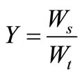 (2)
(2)
while the mass fraction of other waste, X, was determined from the Equation (3):
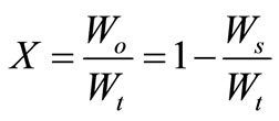 (3)
(3)
3.3. Collection and Weighing of Ashes
The ashes were collected after the chamber has completely cooled down to room temperature, for which the weight of ashes, Was, was determined and compared to the total waste loaded, Wt. Based on the ashes collected, the weight reduction (or weight loss due to incineration), Wr, was determined as per Equation (4):
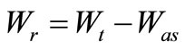 (4)
(4)
Meanwhile, the percent weight reduction, Pwr, was calculated as per equation (5):
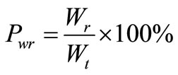 (5)
(5)
3.4. Sieve Analysis Procedure
Sieve analysis involved: weighing of each sieve samples, selection of a representative ash sample to be tested, and weighing a specimen sample of oven-dried ash approximately 250 - 500 g, Sieving of the ash through a nest of sieves was done by automatic shaking machine for at least 20 minutes. Each sieve and pan with the ash retained were weighed again. The weights of the empty pan and sieves were subtracted from the weight of sieves and ash retained on each sieve. The sum of these retained weights was checked against the original ash weight. The results of sieve analysis were expressed in terms of percentage of the total weight of ash that passed through different sieves, of mesh sizes: 250, 150, 90, 63, and 40 µm, followed by a pan at the bottom. Based on weights of ash retained on each sieve, cumulative weights were determined followed by percent pass.
Fineness modulus (FM) which is used for estimating the proportions of fine and course aggregates in particulate mixtures was used in this study from ash particle size distribution and was associated with combustion efficiency. FM is the sum of the total percentages retained on each specified sieve divided by 100. The fineness modulus, Fm1, was determined by arranging the sieve size from the largest size to the smallest size, whereby, the pan and next sieve size were removed. The remaining four sieve sizes were used to calculate the fineness modulus by taking the summation of the percent pass, Pi, divided by 100 as shown in Equation (6):
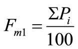 (6)
(6)
Similarly, Fm2 was determined by summing the percent pass without the pan, Pip, leaving the five sieves, as per Equation (7):
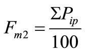 (7)
(7)
ASTM C 33 requires the FM of fine aggregate to be between 2.3 and 3.1 for concrete applications2. Higher fineness modulus represents finer aggregates in the ash which has passed most of the sieves, and hence good combustion efficiency. A value of Fm close to 3.0 signifies acceptable particle sizes for sand, according to this classification. Thus, the ashes from a combustion chamber were compared to the fineness of sand aggregates used in construction industry, as a means of determining combustion efficiency for the medical waste.
4. Results and Discussion
4.1. Loaded Waste and Ash Residual
Medical wastes collected from different sections of the hospital were weighed according to categorization and loaded in to the incinerator. After combustion the remaining ashes (combustible and non combustible) were collected and weighed. The results showed that total waste loaded varied at each run ranging from 83 kg to 122 kg as shown in Table 1. Other waste loaded was observed to be more almost in all runs ranging from 44.5 kg to 65.5 kg comparing to sharps waste which ranged from 14 kg to 63 kg. Ashes collected ranged from 12 kg to 16.8 kg.
In comparing total waste loaded in the combustion chamber (83 kg to 122 kg) and the final ash residual collected after incineration process (12 kg to 16.8 kg) as shown in Figure 1, results indicate that most of the waste loaded was burned properly and the weight reduction has been achieved considerably in all runs. The result also showed that, the ashes collected from incineration process
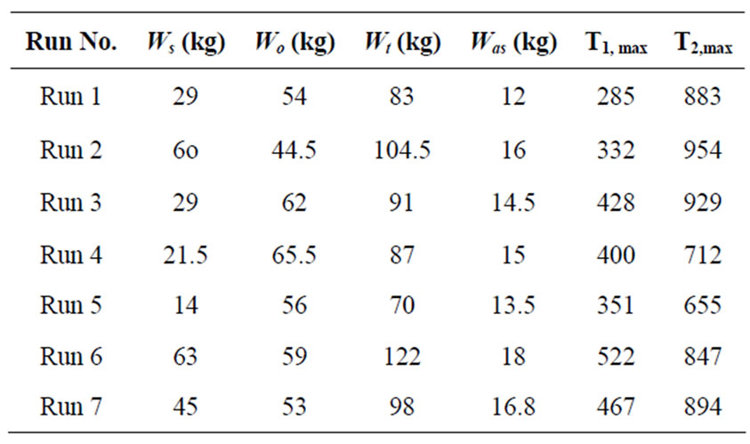
Table 1. Waste loading and ash measurements data.
depend strongly on the total wastes loaded as waste loaded increases the ash residual also increases as shown in Figure 1.
4.2. Separation between Residues and Fine Ash Using Sieve Analysis
The non-combustible materials from Incinerator ash were removed from the mixture as shown in Figure 2. The materials found in the ashes include metal parts, glass and glass ampoules, stones, etc. To give an estimate of the size of the particles, a ball-pen top was inserted in the photos. The particles shown in Figure 2 could not pass through the sieves, which imply that if little amount of ashes pass through the sieve, the fineness modulus will be lower, indicating that the ashes are coarser, and hence the combustion efficiency is low.
After sieving the incinerator ashes appeared in different fineness depending on the sieve size as shown in Figure 3. These particles pass through the sieves, leading to large percent pass and hence higher FM, which implies finer ashes or higher combustion efficiency.
4.3. Sieve Analysis Results
At the laboratory ash residuals were sieved using different sieve sizes; 0 µm, 40 µm, 63 µm, 90 µm, 150 µm and 250 µm respectively in all runs as shown in Figure 4. Despite the variations in sieved ash weight distribution on each sieve, the average weights for different runs gave a curve shown in Figure 5, averaged over the seven (7) runs. These variations were attributed to type and composition of waste being incinerated for a particular run, which depends on the segregation efficiency in the hospital.
However the particle size distribution of ashes fell mainly on the higher sizes of the sieve, which means that,
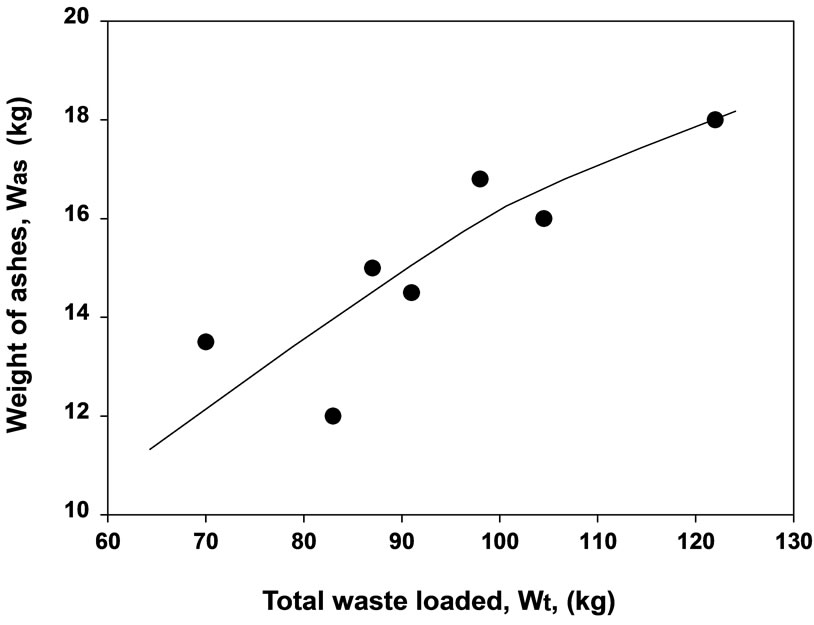
Figure 1. Waste loaded compared to ash residual collected.
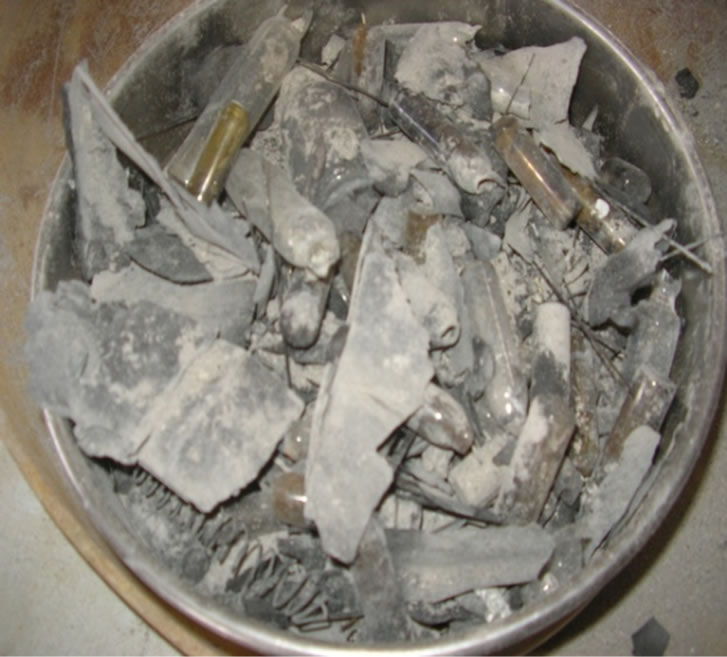
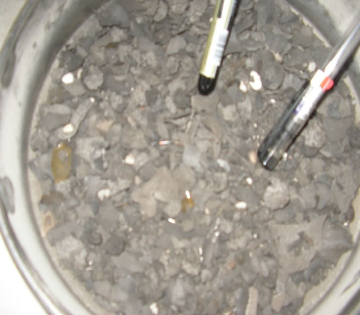
Figure 2. Non-combustible materials from incinerator ash before and after sieving.
most of waste was not burned properly, due to high content of non-combustible materials in the ashes.
4.4. Effect of Amounts of Waste Loaded on Incineration Efficiency
The effect of kg sharps waste on fineness modulus showed that, as mass of sharps waste increases the fineness modulus decreases, that is the ash particles become coarser, as shown in Figure 5. This implies that, sharps waste loaded in the incinerator chamber has significant effect on the fineness modulus, attributable to the noncombustible materials resulting from lower temperatures below 900˚C in most runs.
Although sharps waste lead to high temperature rise in the combustion chamber, when the amount of this waste category is high the amount of non-combustible materials in the ashes increases, leaqding to lower combustion efficiency as revealed by lower fineness modulus in Figure 5. With increasing amounts of sharps, the temperature rises to the maximum and facilitate burning of
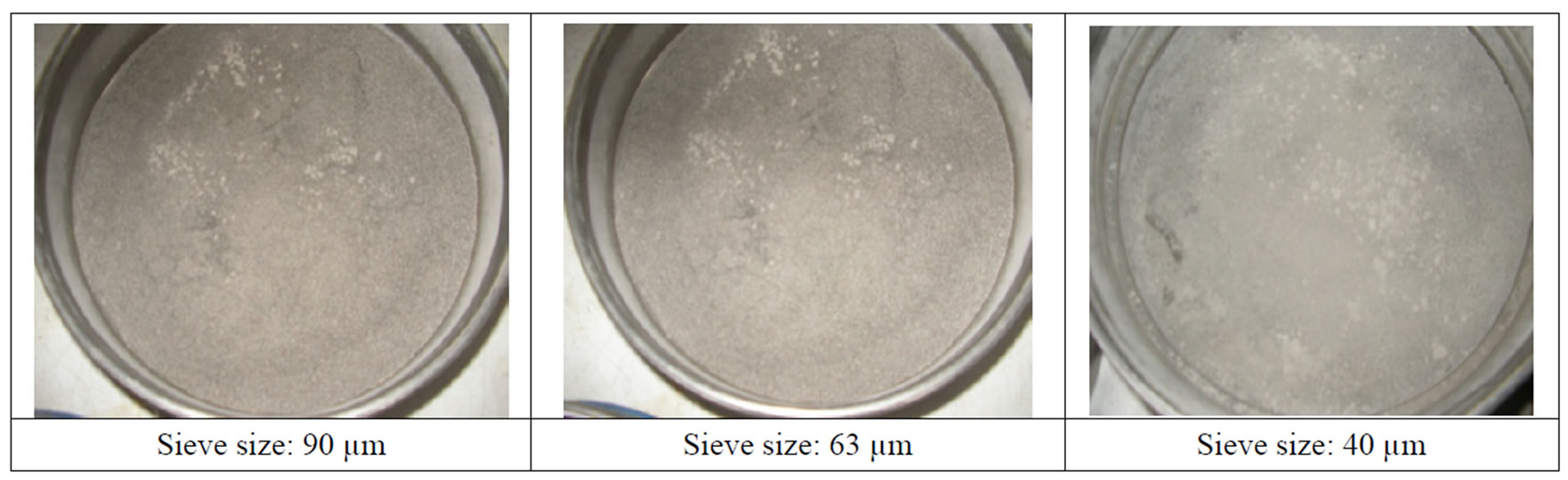
Figure 3. Ashes from incinerator after sieving at different sizes.
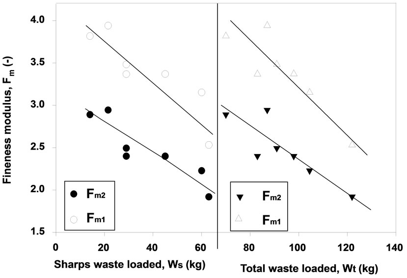
Figure 4. Effect of total waste loaded on fineness modulus.
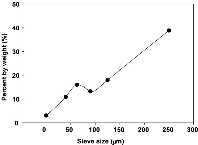
Figure 5. Average ash particle distribution on different sieve sizes.
all waste inside the primary chamber resulting into finer ashes the amopunt of non-combustible materials in the ashes increases.
The decrease in fineness modulus as a result of increased total waste loaded (Figure 5) can be attributed to the increased amount of water in the primary chamber which exceeds the capacity opf the burners leading to poor performance as the non-combustible materials increases.
4.5. Effect of Waste Composition on Incinerator Performance
The effect of mass fraction of other waste X (kg other/kg total waste) on fineness modulus is presented in Figure 6. Results showed that, when mass fraction of other waste increases the fineness modulus increases as well, idicating that, the ashes become less finer. This implises that combustion efficiency increases. That means, loading large propotion of other waste in the incinerator increases the maximum temperature in the combustion chamber leading to efective incineration process with finer ashes. This is also due to the fact that when other waste burn effectively, more ashes are produced and large quantities of fine ashes pass through the sieves, which leads to high combustion efficiency indicated by higher fineness modulus.
Moreover, increasing the mass fraction of sharps waste, Y (kg sharps waste/kg total waste) lowers the fineness modulus, as shown in Figure 6. This implies that loading more sharps decreases the fineness of ashes due to large amount opf non-combustible materials. This can be attributed to the fact that sharps waste contain mostly plastics which burn effectively at higher incineration temperature leading to fine ashes, but the amount of noncombustible materials within the sharps waste increases, lowering the combustion efficiency .
4.6. Effect of Amounts of Waste Loaded on Weight Reduction
The effect of total waste loaded, Wt, on the weight, Wr, is shown in Figure 7. The weight reduction increases linearly with increasing Wt, depicted by a linear equation y = 0.9x – 5.56 with R2 = 0.996. This can be attributed to the fact that when larger amounts of total waste is loaded,
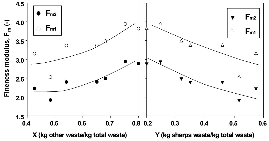
Figure 6. Effect of mass fraction of sharps waste and other waste on fineness modulus.
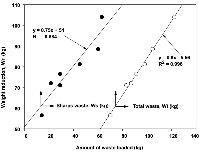
Figure 7. Effect of total waste and sharps waste loaded on weight reduction.
the incineration process becomes more effective as the chamber gains more energy from the waste, elevating the temperature in the chamber and leading to complete destruction of most of the waste. Despite the fact that the amount of ashes will also increase, this has lesser effect than the weight reduction achieved.
The effect of amount of sharps waste loaded into the chamber was observed to increase the weight reduction of the waste, leading to smaller amount of ashes collected, as shown also in Figure 7. This increase in Wr is indicated by a linear curve, represented by an equation: y = 0.75x + 51 with R2 = 0.884, which shows, however, a poor fit, in this case, compared to total waste. Thus more data is needed to establish the true relationship.
4.7. Effect of Waste Composition on Weight Reduction
The mass fraction of sharps waste, Y, affects also the weight reduction, as shown in Figure 8. The results
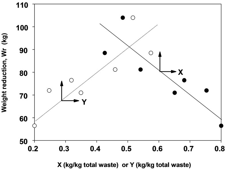
Figure 8. Effect of mass fraction of sharps and other waste on weight reduction.
show that as mass fraction of sharps waste increases the weight reduction, Wr, increases. This is due to the high plastic content which burns faster raising the chamber temperature and leading to effective combustion of the waste. The effect of X on weight reduction, Wr, is presented also in Figure 8. Results show that weight reduction decreases with increasing X, leading to more ashes being collected. The decrease in Wr due to increasing X can be attributed to the fact that more ashes are produced as X increases. Although the general trend is observed on the increase in Wr with Y and decrease in Wr with increasing X, the data was rather scattered, necessitating further studies involving large quantity of data.
4.8. Effect of Waste Composition on Percent Weight Reduction
It was observed that the increase in percent weight reduction shows a maximum, indicating that when Y is too high beyond 0.45, Pwr decreases again, as shown in Figure 9. This is due to the fact that sharps waste increases
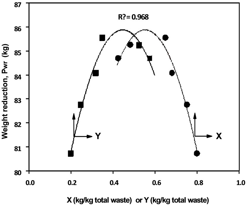
Figure 9. Effect of mass fraction of sharps waste loaded on percent weight reduction.
temperatures more rapidly in the primary combustion chamber, hence more weight reduction of the waste, but when Y is too high, beyond 0.45, the maximum temperature reached in the primary chamber decreases, leading to poor combustion of the rest of the waste, which results into low values of Pwr.
However, the percent weight reduction increases with increasing X up to X = 0.55, beyond which it decreases. This shows that the incinerator performance depends much on the mass fraction of other waste in the combustion chamber as shown in Figure 9. The values of Pwr ranged from 80% to 86% in this study, which indicates higher incinerator performance, as the highest value reported in literature is 90%.
5. Conclusions
Based on the above analysis, it can be concluded that:
1) The ash from the incineration process contains non-combustible materials and fine particles, the former hindering incineration process as it lowers temperature of the primary chamber.
2) The particle size distribution for incinerator ashes shows higher percent for large particle sizes, which do not follow normal distribution.
3) The values of fineness modulus were close to the acceptable value of 3.0, indicating that the incinerator was in the better performance range.
4) The percent weight reduction varies with mass fraction of both sharps waste and other waste in a parabolic manner, with maximum values at Y = 0.35 and X = 0.65.
5) Increasing X or Wo leads to poor incinerator performance as fineness modulus decreases, weight reducetion decreases and also percent reduction decreases (for X > 0.65).
6) Increasing Y or Ws improves incinerator performance, whereby, fineness modulus decreases, weight reduction increases, and percent weight reduction increases (for Y < 0.35).
7) Increasing the total waste loaded into the incinerator primary chamber improves the incinerator performance, such that fineness modulus decreases, Wr and percent weight reduction increases.
8) The maximum temperatures reached in the chambers were lower leading to high fraction of non-combustible materials in the ashes. To improve the incinerator performance further, it was recommended that the medical waste should be stored in a dry place away from rain.
6. Acknowledgements
The completion of this study has been the results of assistance received from Temeke Municipal health officer, District medical officer, Medical Officer in charge and incinerator operator.
7. REFERENCES
- S. V. Manyele, “Medical Waste Management in Tanzania: Current Situation and the Way Forward,” African Journal of Environmental Assessment and Management, Vol. 8, No. 1, 2004, pp. 74-99.
- T. Jeremy and A. Honor, “The Health Effects of Waste Incinerators,” The 4th Report of the British Society for Ecological Medicine, Derby, December 2005.
- S. V. Manyele, “The Role of Engineering in Solving Medical Waste Incineration Problems in Tanzania,” Institution of Engineers Tanzania (IET) Annual Conference, Arusha, 1-2 December 2005, pp. 53-67.
- S. V. Manyele and H. Anicetus, “Management of Medical Waste in Tanzanian Hospitals,” Tanzania Health Research Bulletin, Vol. 8, No. 3, 2006, pp. 177-182.
- S. V. Manyele and T. J. Lyasenga, “Factors Affecting Medical Waste Management in the Lower-Level Health Facilities,” African Journal of Environmental Science and Technology, Vol. 4, No. 5, 2010, pp. 304-318.
- F. Powell, “Air Pollutant Emissions from the Incineration of Hospital Wastes,” Journal of the Air Pollution Control Association, Vol. 37, No. 7, 1987, pp. 836-839.
- J. J. Santoleri, “Design and Operating Problems of Hazardous Waste Incinerators,” Environmental Progress, Vol. 4, No. 4, 2009, pp. 246-251. doi:10.1002/ep.670040408
- J. D. Brady, “Combustion Chemistry & Thermodynamics with Mass & Energy Balances,” 26th Annual International Conference on Incineration and Thermal Treatment Technologies (IT3), Phoenix, 10-14 May 2007.
- IAEA, “Design and Operation of Radioactive Waste Incineration Facilities,” A Safety Guide, Safety Series No. 108, IAEA, Vienna, 1992.
- R. Walter, “Combustion and Incineration Processes,” 3rd Edition, Marcel Dekker, New York, 2002.
- V. J. Landrum, “Medical Waste Management and Disposal,” 2009. http://books.google.co.tz/books/
- L. J. Zhao, F.-S. Zhang, M. J. Chen, Z. G. Liu and J. Z. Wu, “Typical Pollutants in Bottom Ashes from a Typical Medical Waste Incinerator,” Journal of Hazardous Materials, Vol. 173, No. 1-3, 2010, pp. 181-185.
- R. R. Groner, “The Chemical Transformation of Solid Wastes,” AICHE Symposium Series, Vol. 68, No. 122, 1972, pp. 28-39.
- J. R. McDougall and I. C. Pyrah, “Moisture Effects in a Biodegradation Model for Waste Refuse,” In: T. H. Christensen, R. Cossu and R. Stegmann, Eds., Proceedings of Sardinia’99 7th Waste Management and Landfill Symposium, CISA, Cagliari, Vol. 1, 1999, pp. 59-66..
- E. Gidarakos, M. Petrantonaki, K. Anastasiadou and W. Schramm, “Characterization and Hazard Evaluation of Bottom Ash Produced from Incinerated Hospital Waste,” Journal of Hazardous Materials, Vol. 172; No. 2-3, 2009, pp. 935-942. doi:10.1016/j.jhazmat.2009.07.080
- S. Singh and V. Prakash, “Toxic Environmental Releases from Medical Waste Incineration: A Review,” Environmental Monitoring, Vol. 132, 2007, pp. 67-81.
NOTES
1http://www.rielloburners.co.uk.
2fttp://ftp.ebuild.com/woc/J940107.pdf