Engineering
Vol. 3 No. 7 (2011) , Article ID: 6152 , 5 pages DOI:10.4236/eng.2011.37090
A Kind of Potential Practical Sensors of Metamaterial in Electromagnetic Flaw Nondestructive Testing
The First Aeronautical Institute of Air Force PLA, Xinyang, China
E-mail: xxuy@163.com, xuzhanxian@sohu.com
Received November 2, 2010; revised May 31, 2011; accepted June 10, 2011
Keywords: Metamaterial, Nondestructive, Flaw, Ansoft HFSS Software, Sensor
ABSTRACT
We present a new kind of method of electromagnetic flaw nondestructive testing with coating of metamaterials and simulation near electromagnetic field property for test crack. The simulation of improving a Nondestructive testing (NDT) probe electromagnetic radiant property by Metamatrials (MMs) covering a tiny current element is investigated and analyzed using Ansoft HFSS based on finite element method (FEM), which permittivity and permeability are negative. Electromagnetic model: Ideal MMs ball shell with inner radius of 1 mm and outer radius variation, and the shell’s relative permittivity and relative permeability are all –3.0, dielectric loss tangent and magnetic loss tangent are all 0.1; and exciting current element length is with 0.3 mm, diameter 0.2 mm, value 1 mA at frequency 10 GHz; and simulation is with radiation boundary conditions. The simulating near electromagnetic field variety with ratio of inner radius and out radius, and so near or local field of MMs sensor on a surface crack, as well as comparing near field value of sensor with coating common material are finished. Results can be seen that MMs film sensor near electromagnetic field and radiation properties are obviously better than other two kinds of structures without coating medium and coating with common medium, and Metamaterial may be opened out some new kinds of sensors in electromagnetic flaw nondestructive testing for potential practical applications in future.
1. Introduction
In 1967, Veselago theoretically considered a homogeneous isotropic electromagnetic material in which both permittivity and permeability were assumed to have negative real values. Since the E, H fields and the wave vector k of a propagating plane EM wave form a left-handed system in these materials, Veselago referred to them as “left-handed” media, or metamaterial media [1-3]. In such a medium, he concluded, the direction of the Poynting vector of a monochromatic plane wave is opposite to that of its phase velocity. It suggests that this isotropic medium supports backward-wave propagation and its refractive index can be regarded negative. Since these materials were not available until recently, the interesting concept of negative refraction, and its various electromagnetic and optical consequences, suggested by Veselago, had received little attention. This was until Smith et al. [4], inspired by the work of Pendry et al. [3,5] constructed a composite “medium” in the microwave regime by arranging periodic arrays of small metallic wires and split-ring resonators [4,6-9] and demonstrated the anomalous refraction at the boundary of this medium, which is the result of negative refraction in this artificial medium [8]. Metamaterials are broadly defined as artificial effectively homogeneous electromagnetic structures with unusual properties not readily available in nature. This opened the field of composite materials or metamaterials for microwaves and optical applications. Since the idea proposed by Victor Veselago in 1968, the availability of such a material is taken up nowadays and extended [10-21]. In this paper, we present a new kind of sensor of electromagnetic flaw nondestructive testing with coating of metamaterial and then apply it to simulate near electromagnetic field property for test crack. Our aim is to find out some application of metamaterial covering in sensor through better field design, and this method can greatly improve the near electromagnetic field and radiation properties of the transducer.
2. Split Ring Resonators (SRRs)
Double split ring resonator (SRR) is a common kind of metamaterial cell, and conductive structure in which the capacitance between the two rings balances its inductance, Figure 1. A time-varying magnetic field applied perpendicular to the rings surface induces currents which in dependence on the resonant properties of the structure, produce a magnetic field that may either oppose or enhance the incident field, thus resulting in positive or negative effective μ. For a circular double split ring resonator in vacuum and with a negligible thickness, the following approximate expression is valid [22]:
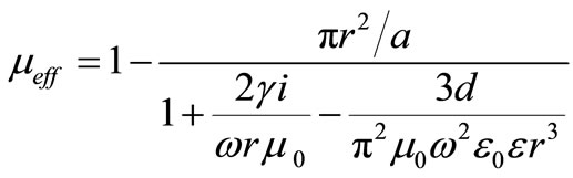 (1)
(1)
where, a is the unit cell length, and g is electrical conductance. It becomes negative for ω0m < ω < ωpm, where ω0m is the resonant frequency (for which μeff → ± ∞); ωpm is the magnetic plasma frequency (for which μeff → 0). Usually, there is a narrow frequency range where the μeff < 0.
Thin metallic wires were described as one of the earliest structures with negative permittivity ε, and the media with the embedded thin metallic wires can be as artificial dielectrics for microwave applications, Figure 2. The structure with ε < 0 described by Pendry consists of a square matrix of infinitely long parallel thin metal wires embedded in dielectric medium. In the situation, the medium is air or vacuum, and the radius of a single wire is very thinner than the distance between two wires, that is , the effective dielectric permittivity can be written as follow [23]:
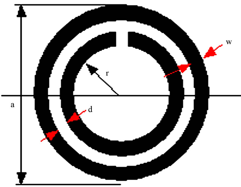
Figure 1. Double split ring resonator (SRR).
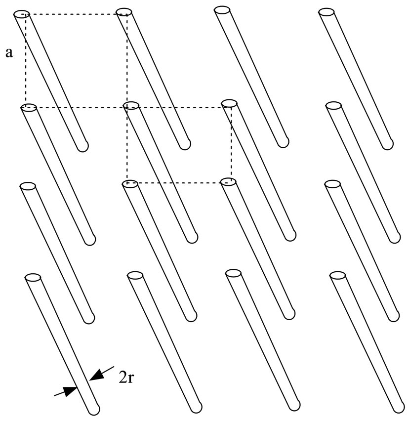
Figure 2. Periodic arrays metallic wires.
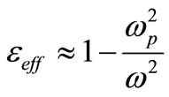 (2)
(2)
where, ωp is the plasma frequency for the longitudinal plasma mode. Clearly, it becomes negative for ω < ωp.
3. Metamaterial Sensor Simulation
Simulation of improving the Nondestructive testing (NDT) transducer electromagnetic radiant property by Metamatrials (MMs) covering a tiny current element is investigated and analyzed using Ansoft HFSS based on finite element method (FEM), which permittivity and relative permeability are negative.
3.1. Electromagnetic Model and Assigning Materials
The ideal MMs ball shell film is with inner radius of 1 mm and outer radius variation, and the shell’s relative permittivity and relative permeability are all –3.0, dielectric loss tangent and magnetic loss tangent are all 0.1.
3.2. Selecting the Solution Type
Choose the Driven Modal solution type when we want HFSS to calculate the modal-based S-parameters of passive, high-frequency structures such as micro strips, waveguides, sensors, and transmission lines. The S-matrix solutions will be expressed in terms of the incident and reflected powers of waveguide modes.
3.3. Assigning Boundaries Assigning Boundaries and Assigning Excitations
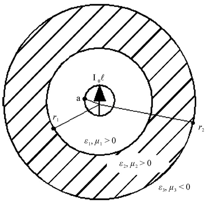
For Driven Modal, a radiation boundary is used to simulate an open problem that allows waves to radiate infinitely far into space, such as antenna designs. HFSS absorbs the wave at the radiation boundary, essentially ballooning the boundary infinitely far away from the structure. A radiation surface does not have to be spherecal, but it must be exposed to the background, convex with regard to the radiation source, and located at least a quarter wavelengths from the radiating source. In some cases the radiation boundary may be located closer than one-quarter wavelength, such as portions of the radiation boundary where little radiated energy is expected. Here, simulation is with radiation boundary conditions. See Figure 3.
Excitations in HFSS are used to specify the sources of electromagnetic fields and charges, currents, or voltages on objects or surfaces in the design. We may assign the current source of excitations to a Driven Modal solution type HFSS design, and exciting current element length is with 0.3 mm, diameter 0.2 mm, value 1 mA at frequency of 10 GHz.
4. Running Simulations and Conclusions
After specify how HFSS is to compute the solution, we begin the solution process. Adaptive solution, maximum number of 15, and maximum delta energy 0.08 are selected for solution setup, we get some results as following: For three kinds of states of a sensor with coating MMs, those are coating common medium and without coating, simulating near electromagnetic field variety with ratio of inner radius and out radius, see Figure 4. Near field is that one its distance less than 20 mm from exciting source point. Suppose test an aluminum work piece with surface crack by the MMs sensor with r1/r2 = 0.5, crack length 6 mm, width 1 mm, and depth 0.1 mm, the near field around crack flaw see Figure 5; and comparing to near field value of probe with coating common material see Figure 6. Results can be seen from Figure 4 that for MMs film sensor, near electromagnetic field property is obviously better than other two kinds of structures without coating medium and coating with common medium, and near field value is variety of ratio inner radius and out radius. When r1/r2 = 0.5 and no load, near and local field of MMs sensor can reach to 10 dB, but only –21 dB for sensor with coating common medium, and –22 dB for sensor without coating any medium. We get from Figure 6 that near field of a MMs sensor is higher about 30 dB than one of transducer coating common medium when r1/r2 = 0.5 and with load.
 (a)
(a)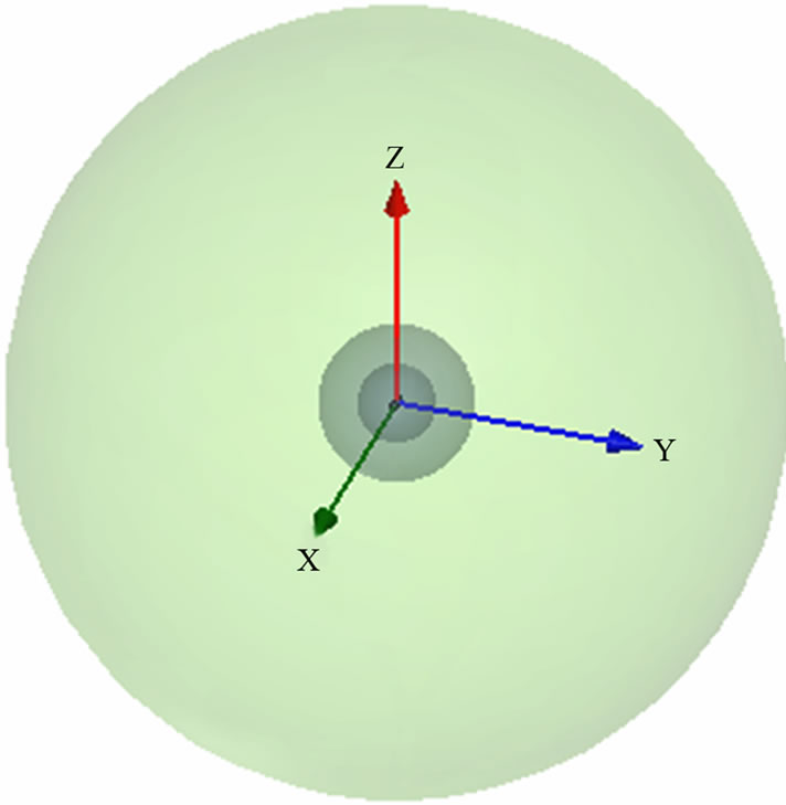 (b)
(b)
Figure 3. Electromagnetic model. (a) Geometrical structure; (b) Simulation structure.
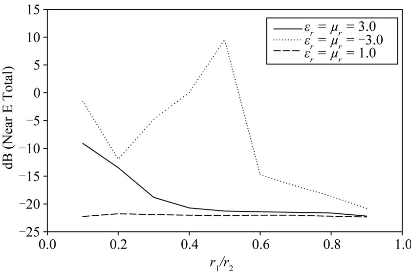
Figure 4. Simulating near electromagnetic field variety with the ratio of inner radius and out radius.
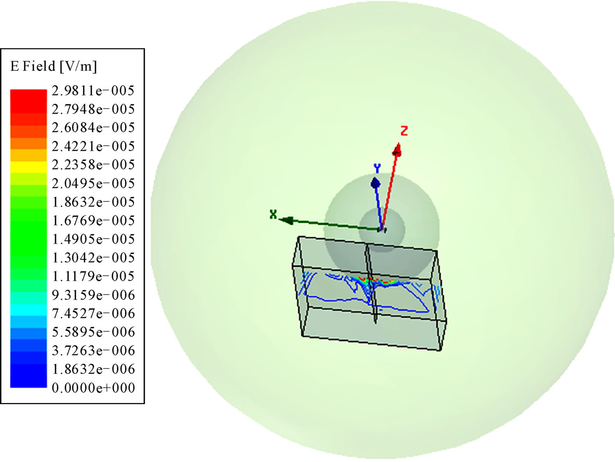
Figure 5. Near and local field of MMs sensor on suface flaw (r1/r2 = 0.5).
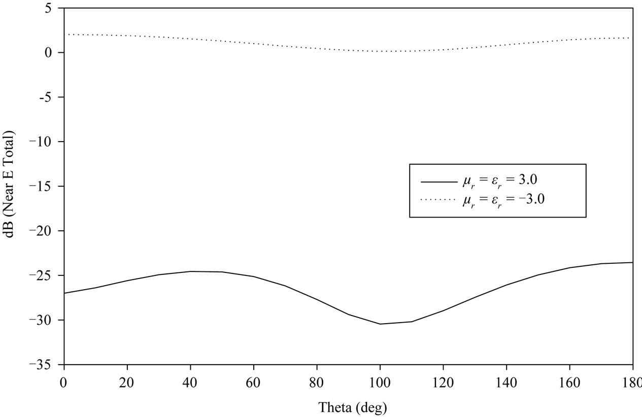
Figure 6. Comparing to near field value of sensors with the coating MMs and common material.
Similarly, radiation power of MMs sensor can reach to –53 dB, but only –74 dB for sensor with coating common medium, and –75 dB for sensor without coating any medium. MMs sensor is higher about 20 dB than one of transducer coating common medium. Near field and radiation power are both important properties of a sensor. From above results, we know that MMs film sensor is excellent for near electromagnetic field and radiation properties. So some metamaterial nondestructive electromagnetic sensors including sound wave transducer may be opened out for potential practical applications in future.
5. REFERENCES
- V. G. Veselago, “The Electrodynamics of Substances with Simultaneously Negative Values of ε and µ,” Soviet Physics Uspekhi, Vol. 10, No. 4, 1968, pp. 509-514. doi:10.1070/PU1968v010n04ABEH003699
- V. G. Veselago, “The Electrodynamics of Substances with Simultaneously Negative Values of ε and µ,” Uspekhi Fizicheskikh Nauk, Vol. 92, 1967, pp. 517-526.
- J. B. Pendry, A. J. Holden, D. J. Robbins, et al., “Low-Frequency Plasmons in Thin Wire Structures,” Journal of Physics Condensed Matter, Vol. 10, No. 22, 1998, pp. 4785-4809. doi:10.1088/0953-8984/10/22/007
- D. R. Smith, W. J. Padilla, D. C. Vier, et al., “Composite Medium with Simultaneously Negative Permeability and Permittivity,” Physical Review Letters, Vol. 84, No. 18, May 2000, pp. 4184-4187. doi:10.1103/PhysRevLett.84.4184
- J. B. Pendry, A. J. Holden, D. J. Robbins, et al., “Magnetism from Conductors and Enhanced Nonlinear Phenomena,” IEEE Transactions on Microwave Theory and Techniques, Vol. 47, No. 11, 1999, pp. 2075-2081. doi:10.1109/22.798002
- D. R. Smith and N. Kroll, “Negative Refractive Index in Left-Handed Materials,” Physical Review Letters, Vol. 85, No. 14, 2000, pp. 2933-2936. doi:10.1103/PhysRevLett.85.2933
- R. A. Shelby, D. R. Smith, S. C. Nemat-Nasser, et al., “Microwave Transmission through a Two-Dimensional, Isotropic, Left-Handed Metamaterial,” Applied Physics Letters, Vol. 78, No. 4, 2001, pp. 489-491. doi:10.1063/1.1343489
- A. Shelby, D. R. Smith and S. Schultz, “Experimental Verification of a Negative Index of Refraction,” Science, Vol. 292, No. 5514, 2001, pp. 77-79. doi:10.1126/science.1058847
- N. Engheta and R. W. Ziolkowski, “A Positive Future for Double-Negative Metamaterials,” IEEE Transactions on Microwave Theory and Techniques, Vol. 53, No. 4, 2005, pp. 1535-1556. doi:10.1109/TMTT.2005.845188
- S. Enoch, G. Tayeb, P. Sabouroux, N. Guerin, et al., “A Metamaterial for Directive Emission,” Physical Review Letters, Vol. 89, No. 21, 2002, Article ID: 213902. doi:10.1103/PhysRevLett.89.213902
- B. Li, B. Wu and C.-H. Liang, “Study on Hign Gain Circular Waveguide Array Antenna with Metamaterial Structure,” Progress in Electromagnetics Research, Vol. 60, 2006, pp. 207-219. doi:10.2528/PIER05121101
- A.-K. Hamid, “Axially Slotted Antenna on a Circular or Elliptic Cylinder Coated with Metamaterials,” Progress in Electromagnetics Research, Vol. 51, 2005, pp. 329- 341. doi:10.2528/PIER04082301
- J. B Pendry, A. J. Holden, W. J. Stewart, et al., “Extremely Low Frequency Plasmons in Metallic Microstructures,” Physical Review Letters, Vol. 76, No. 25, 1996, pp. 4773-4776. doi:10.1103/PhysRevLett.76.4773
- C. G. Parazzoli, R. B. Greegor, J. A. Nielsen, et al., “Performance of a Negative Index of Refraction Lens,” Physical Review Letters, Vol. 84, No. 17, 2004, pp. 3232- 3234.
- J. B. Pendry and D. R. Smith, “Reversing Light with Negative Refraction,” Physics Today, Vol. 57, No. 6, 2004, pp. 37-43. doi:10.1063/1.1784272
- Z. X. Xu and W. G. Lin, “Controllable Absorbing Structure of Metamaterial at Microwave,” Progress in Electromagnetics Research, Vol. 69, 2007, pp. 117-125. doi:10.2528/PIER06120801
- W. M. Zhu, A. Q. Liu, X. M. Zhang, et al., “Switchable Magnetic Metamaterials Using Micromachining Processes,” Advanced Materials, Vol. 23, No. 15, 2011, pp. 1792-1796. doi:10.1002/adma.201004341
- P. N. Li, Y. W. Liu, Y. J. Meng, et al., “A Multifrequency Cloak with a Single Shell of Negative Index Metamaterials,” Chinese Physics Letters, Vol. 28, No. 6, 2011, Article ID: 064206. doi:10.1088/0256-307X/28/6/064206
- J. Hu, C. S. Yan and Q. C. Lin, “A New Patch Antenna with Metamaterial Cover,” Journal of Zhejiang University—Science A, Vol. 7, No. 1, 2006, pp. 89-94.
- H. S. Chen, “Metamaterials: Constitutive Parameters, Performance, and Chemical Methods for Realization,” Journal of Materials Chemistry, Vol. 21, No. 18, 2011, p. 6452. doi:10.1039/c0jm03138k
- L. Huang and H. S. Chen, “Multi-Band and Polarization Insensitive Metamaterial Absorber,” Progress in Electromagnetic Research-PIER, Vol. 113, 2011, pp. 103-110.
- Z. Jaksic, N. Dalarsson and M. Maksimovic, “Electromagnetic Structures Containing Negative Refractive Index Metamaterials,” TELSIKS, Vol. 1, 2005, pp. 145-154.
- R. Marques, J. Martel, F. Mesa, et al., “Left-HandedMedia Simulation and Transmission of EM Waves in Subwavelength Split-Ring-Resonator-Loaded Metallic Waveguides,” Physical Review Letters, Vol. 89, No. 18, 2002, pp. 183901-183904. doi:10.1103/PhysRevLett.89.183901