Materials Sciences and Applications
Vol.3 No.11(2012), Article ID:24950,8 pages DOI:10.4236/msa.2012.311119
Modeling and Numerical Simulations with Compressible Damaged Hyperelastic Law: Application to the Laminated Rubber Bearing
![]()
1Laboratoire de Mécanique de Sousse, Université de Sousse (ENISo) Technopôle de Sousse, Sousse, Tunisia; 2Laboratoire de Mécanique et d’Acoustique de Marseille, Technopôle de Château-Gombert, Marseille Cedex, France.
Email: Zaghdoudi_maha@yahoo.fr
Received August 17th, 2012; revised September 15th, 2012; accepted October 12th, 2012
Keywords: Elastomer and Rubber; Failure Analysis; Mechanical Behavior
ABSTRACT
Hyperelastic model with damage induced compressibility is implemented in the ABAQUS software using the subroutine Umat. A thermodynamic model is proposed taking into account the nonlinearity of the material behavior. Within the present work, the behavior of laminated rubber bearing structure is studied for two geometrical sets of materials (A-type and equivalent material) under complex monotonic loading conditions. A new geometric edge of laminated rubber bearing is proposed in order to reduce the development costs of the structure. The proposed model allowed finding a good homogenized damage distribution for the same overall stiffness.
1. Introduction
Rubber, thermoplastics and nano-composites with polymeric matrix are recent materials compared with metallic materials. These rubbers-like materials are frequently used in different fields such as the automobile and aeronautic industries. They are known to undergo large elastic strains and highly non-linear behavior, sensitive to the strain rate and the temperature. Moreover, their mechanical response varies according to the degree of cross linking as well as the incorporated particles nature and volume fraction.
Several models have been proposed and developed in literature in accordance with various phenomena: modeling of the continuum damage due to the Mullins effect, visco-hyperelastic approach with continuous and discontinues damage concept, thermo mechanical coupling and hyperelasticity investigations in the case of monotonic loading.
The first pioneers working in this field are Rivlin, Treloar and Ogden [1-3]. They developed incompressible hyperelastic laws which were successfully implemented in most finite elements software like ABAQUS. However, recent studies assume that these materials have a compressible hyperelastic behavior sensitive to the strain rate and they report that a volume variation is often observed due to the damage process [4-12].
In this paper, a compressible hyperelastic law is implemented and coupled with the damage induced by the compressibility effect. This law is written in a thermodynamic formalism with an irreversible process according to the phenomenological approach (local method) developed by Lemaître and Chaboche [13]. This approach is based on experimental observation results where a state variable is used to reproduce each identified experimental process. It is found that laws formulated with this approach are in agreement with mass and energy conservation principles as well as the first and the second thermodynamics laws.
In this work, we will firstly introduce and define the state variables and the free energy function used in this study. The potential dissipation and the damage criteria surface will then be presented. A Neo-Hooke law coupled with damage and a Mooney Rivlin law are subsequently adopted and implemented in ABAQUS through the user subroutine Umat. Illustrative examples of the model use are ultimately given.
2. Model Formulation
2.1. Thermodynamic Potential
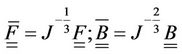
In the present work, the main interest is the study of damaged compressible hyperelastic isothermal behavior laws. The compressibility effect is induced by damage growth. The state potential is built on the base of two observable state variables: B the left Cauchy Green tensor, and D the scalar variable describing the evolution of the isotropic damage, considered as the only source of energy dissipation. The multiplicative decomposition of the deformation gradient  and of the left CauchyGreen tensor B into dilational and distortional parts is adopted. The modified (barred) tensors (Equation (1)) are associated with volume-preserving deformations, while the jacobian J accounts for volumetric changes.
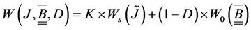
The uncoupled form of the free energy in a volumetric and isochoric contribution written in terms of the transformation jacobian J is given by the Equation (2).
 (1)
(1)
 (2)
(2)
where:
-  and
and  are the spherical and the deviatoric part of the potential, respectively.
- K is the compressibility modulus of material.
- J is the effective variable of J given by:
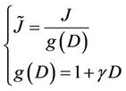 (3)
(3)
In Equation (3),  is a positive increasing function of D and
  is an intrinsic material parameter, usually taken between 0 and 1. The deviatoric part of the potential
 , represents the deformation energy of undamaged solid (incompressible part, i.e. deviatoric part of the state potential or distortional part) affected by
  due to the damage effect. The fundamental Clausius-Duhem inequality is written as follows:
 (4)
(4)
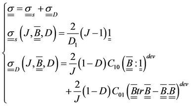
The associate thermodynamic forces (states relations) given in Equations (5) and (6) are the Kirchhoff stress tensor  and the thermodynamic damage force Y.
Similar to the state potential, these forces are decomposed into a spherical part (of pure volumetric compression), and a distortional part (incompressible or isochoric) as follows:
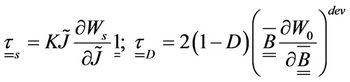 (5)
(5)
 (6)
(6)
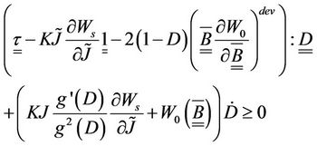
The dissipation condition is represented by the following equation:
 (7)
(7)
2.2. Damage Description
The damage evolution is described by the convex of non damage that is available at any time of the loading history [8,9] as follows:
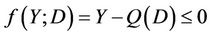 (8)
(8)
where  is a positive increasing function of D, giving the size of the damage surface in the deformation space. In this work, a simple form of
  is chosen as:
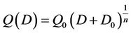 (9)
(9)
where ,
,  and n are constant material parameters. According to the standard normality argument, the damage evolution law is integrated using the following system of equations:
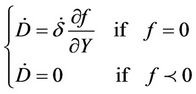 (10)
(10)
where  is the damage multiplier. Using the consistency condition (i.e.
  ), the damage evolution law can be determined by:
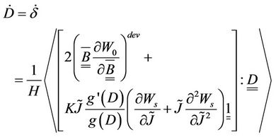 (11)
(11)
where (*)dev denotes the deviatoric part of *,  is a positive scalar defined by:
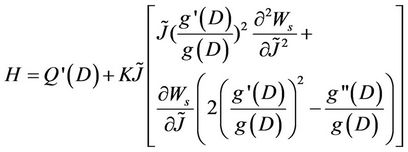 (12)
(12)
2.3. Application to the Hyperelastic Models
The formulation of the Mooney Rivlin potential proposed initially by Mooney used in the studies [1,2] will be adopted in the present work. From a mechanical viewpoint, this law has the advantage of being stable which is expressed as follows:
 (13)
(13)
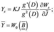
The state relations that define the damaged hyperelastic behavior are described by:
 (14)
(14)
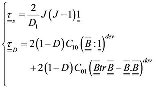
The Cauchy stress tensor is described by the following equations system:
 (15)
(15)
2.4. Implementation Procedure
In the previous section, a Mooney Rivlin law coupled with damage is defined. This law is implemented in the commercial code ABAQUS/implicit using a new material behavior through the user subroutine Umat. ABAQUS/ implicit is based on an iterative solver like the NewtonRaphson scheme that needs the determination of the tangent matrix  . This matrix must be consistent with the integrated scheme of the previous developed constitutive equations by means of the differential form of the Kirchoff stress tensor:
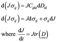 (16)
(16)
where  is obtained as follows in component form:
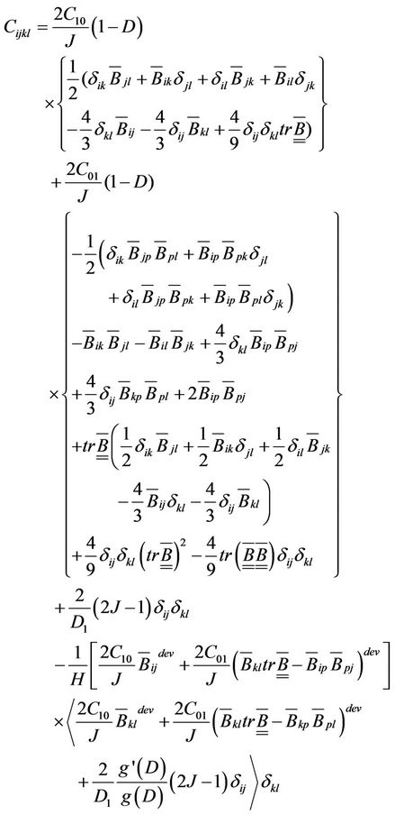 (17)
(17)
3. Application to a Laminated Rubber Bearing
As an application for the proposed model we choose a bridge which consists mainly of bridge deck supported by piers. The laminated rubber bearing with cylindrical shape is placed between the bridge deck and the piers. Bridge bearings are devices used for transferring loads and displacements from deck to piers. Their main role is to avoid damage during thermal expansion, vehicular motion and loading to piers. Neoprene is the material used for the bridge bearing which contains two rigid frames (RM) (see Figure 1). This hyperelastic material is used to accommodate the displacement without transmitting harmful stress. The Neoprene material (NM) is also
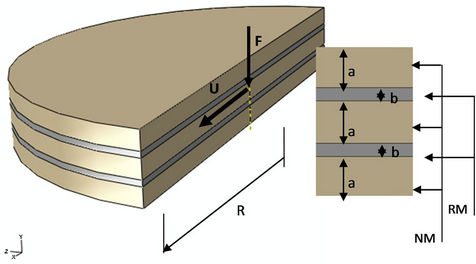
Figure 1. Laminated rubber bearing model constituted by three layers in Neoprene (NM) and two armatures in rigid material (RM with E = 200 GPa and n = 0.3).
able to absorb and isolate energy resulting from impacts and vibrations. The proposed hyperelastic model coupled with damage is implemented in the FE (finite elements) application using ABAQUS code through the Umat subroutine. The damage parameters are shown in Table 1, where K,  and
and  are the compressible parameters. The intrinsic material parameter
  relates to the rate dependence of the damage induced by compressibility (Equation (3)).
  ,
,  and n represent the parameters of the chosen potential of damage (Equation (11)). Two loading steps are imposed on the structure. A compression loading is applied during a first step up to 24 tons along F direction. At this level of charge, a 10 mm shear displacement is imposed in a second step along the U direction as illustrated by Figure 1. The overall results will be discussed in the following sections for two cases: Neo-Hooke and Mooney Rivlin potentials applied for both cylindrical (common) and chamfered edge case.
3.1. Cylindrical Shape
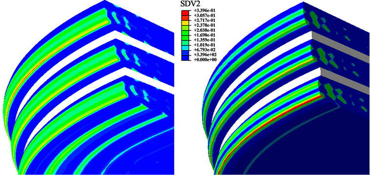
The previously described equations are integrated to an ordinary geometry of the laminated rubber bearing using a cylindrical shape as shown in Figure 1. Because of the geometrical symmetry of the parts, only half of the structure is modeled using 3D hybrid quadratic brick C3D20H elements. Table 1 summarizes the geometric, material and loading parameters. The rubber bands have the well known cylindrical shape where the neoprene material (A-type) is affected for the three layers. Applying the Neo-Hooke hyperelastic potential  , the damage distribution shown in Figure 2(a) presents a pronounced disparity in such values especially in the lower band near the interface with the frame where the maximum reaches 34%.
In order to better homogenize the damage distribution through the overall structure, we propose to consider different materials for the three neoprene bands. The so called “equivalent material” is then used. It consists of affecting the set B, C and D for the upper, middle and lower band respectively. The results can be clearly observed in Figure 2(b), where the damage distribution does not present any particular concentration and the overall stiffness remains slightly unchanged. Moreover, the evolution of damage and Von Mises stress versus true strain in the integration point which presents the maximum value is illustrated in Figure 3 for both A-type material and the equivalent material. It appears clearly that for the coupled case the stress level decreases and the damage is higher for the A-type material compared to the equivalent material. The disparity of damage evolution between the two configurations increases for deformations beyond 10% as illustrated in Figure 3.
At the same integration point, the damage evolution changes position from compression to shear as shown in Figure 4. This behavior could be attributed to the low drop in the equivalent stiffness of the structure which is more sensitive in shear than in compression. This is due to the imposed higher displacements.
3.2. Chamfered Edge
In a second step, a chamfered edge is adopted as a new geometrical model where the A-type material is considered for the whole structure. Figure 5 shows the proposed model meshed using 8481 3D 20-node quadratic brick hybrid elements. The overall stiffness of the structure is highlighted in both compression and shear loading for the cylindrical and the chamfered edge geometry. With shear loading the coupled behavior is more noticeable in the chamfered case compared to the cylindrical case for the damage evolution.
Subsequently, the impact of the chamfered edge on the damage distribution is well characterized by a better homogenous distribution as shown in Figure 6 compared to the above mentioned cylindrical shape using the same material conditions (Figure 2(a)).
3.3. Extension to the Mooney Rivlin Potential (Chamfered Case)
The model equations described above are integrated according to the Mooney Rivlin law. Figure 7 shows the overall stiffness of the laminated rubber bearing using the Mooney Rivlin (simple line) and the Neo-Hooke model (marked line). A significant discrepancy in the predicted stiffness is found between the two results. It appears clearly that the Neo-Hooke model underestimates the stiffness of the structure.
This could be due to the corrective term  that better defines the cross-linkage density of the hyper elastic material. In fact, it is well known that the crosslinking increases with a drop of the
  ratio; i.e.
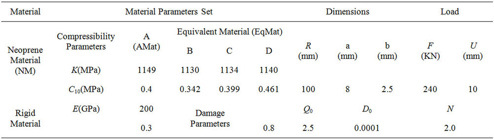
Table 1. Geometric, load and material parameters of the laminated rubber bearing used during simulations.
 (a) (b)
Figure 2. Damage distribution in three layers of laminated rubber bearing: (a) The material A (AMat) is used; (b) The equivalent material B, C and D (EqMat) is used.
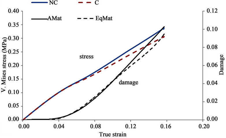
Figure 3. Equivalent Von Mises and damage vs. true train in the chosen element number (see Figure 2(a)): Stress in compression case (NCS: non coupled stress, CS: coupled stress); Damage in compression (AMat: damage where the material A is used, EqMat: damage where the equivalent material B, C and D is used).

Figure 4. Damage vs. time resolution in the chosen element number (see Figure 2(a)): Damage where the material A is used (AMat); Damage where the equivalent material B, C and D is used (EqMat).
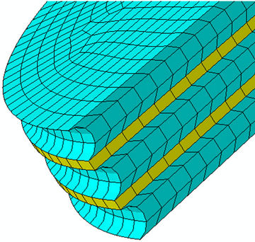
Figure 5. Meshed view representing a partial of the laminated rubber bearing with a chamfered edge in the three layers of neoprene material.
microscopically speaking, the molecule chains are shorter and more entangled. Such behavior expressed by a decrease in the overall stiffness of the structure seems to be in agreement with the Neo-Hooke model.
The consistency of the Mooney Rivlin law in comparison with the Neo-Hooke model is also shown in Figure 8 where the damage evolution is better described. This figure emphasizes the high level of nonlinearity with shear loading starting from t = 1 s in time axis. This non linearity is well established by Mooney Rivlin law (simple line) where the Neo-Hooke model faces a convergence issues (marked line). This result is in agreement with most investigations conducted in the literature
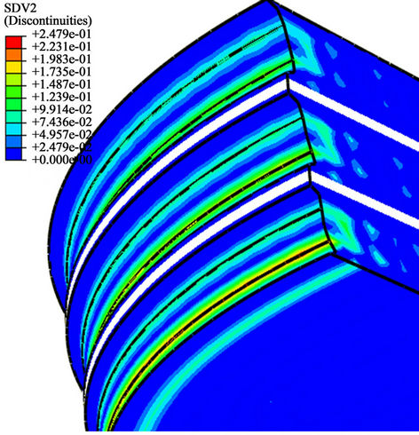
Figure 6. Damage distribution in three layers of laminated rubber bearing using material A with a chamfered edge structure.
where the applicability of the Neo-Hooke model does not exceed 60% of deformation [14]. Furthermore, it is well known that the mobility of the molecular chains is related to the material coefficients  and
and  . The motion of the molecular chains is affected by the increase of
  value which in turn increases the material energy dissipation.
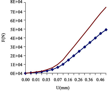
Figure 7. Stiffness evolution considering the two hyperelastic potentials: Neo-Hooke in marked and Mooney-Rivlin in simple line.
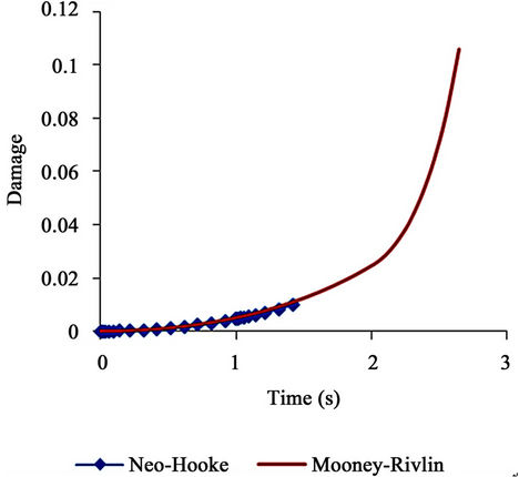
Figure 8. Damage evolution considering the two hyper-elastic potentials: Neo-Hooke in marked and Mooney-Rivlin in simple line.
4. Conclusions
A numerical tool based on the finite elements method is developed to predict the behavior of the damage induced compressibility of a hyperelastic structure subjected to a monotonic loading (compression and shearing). This formalism is applied to the case of a laminated rubber bearing for different geometrical sets of materials. We found that damage prediction could be improved using an equivalent material instead of the A-type one. A new approach is adopted to better homogenize the damage distribution by substituting the exterior cylindrical shape with a chamfered edge while maintaining the initial A-type material. The comparison between the Neo-Hooke and Mooney Rivlin model highlights the ability of the Mooney Rivlin model to predict not only the stiffness of the structure but also the damage evolution with a highly non linear behavior.
Future works will focus on the extension of this formalism by taking into account the stress softening, hysteresis loss and cyclic softening in the random fatigue case. This will enable us to predict the fatigue strength of this new laminated rubber bearing. Such analysis is currently in progress and material parameters will be identified from experimental responses.
REFERENCES
- R. S. Rivlin and D. W. Saunders, “Large Elastic Deformations of Isotropic Materials. VII. Experiments on the Deformation of Rubber,” Philosophical Transactions of the Royal Society of London Serie A, Vol. 243, No. 865, 1951, pp. 251-288. doi:10.1098/rsta.1951.0004
- L. R. G. Treloar, “Stress-Strain Data for Vulcanized Rubber under Various Types of Deformation,” Transactions Faraday Society, Vol. 40, 1944, pp. 59-70. doi:10.1039/tf9444000059
- R. W. Ogden, “Non Linear Elastic Deformations,” Editora Horwood, Halsted Press, New York, 1984, p. 532.
- R. J. Farris, “The Influence of Vacuole Formation on the Response and Failure of Filled Elastomers,” Transactions of the Society of Rheology, Vol. 12, No. 2, 1968, pp. 315- 334. doi:10.1122/1.549111
- N. A. Hocine, A. Hamdi, M. N. Abdelaziz, P. Heuillet and F. Zaïri, “Experimental and Finite Element Investigation of Void Nucleation in Rubber-Like Materials,” International Journal of Solids and Structures, Vol. 48, No. 9, 2011, pp. 1248-1254. doi:10.1016/j.ijsolstr.2011.01.009
- F. Jazzar, “Numerical Simulation of the Quasi-Incompressible Hyperelastic Behaviour of Rubber with Steel Plates Structures and Experimental Validation,” PhD. Thesis, Aix-Marseille II University, 1993.
- F. Andrieux, “On Damaged Visco-Hyperelastic Media,” PhD. Thesis, UTC Compiegne, 1996.
- F. Andrieux, K. Saanouni and F. Sidoroff, “On Hyperelastic Solids with Damage Induced Compressibility,” Mechanics of Solids and Structures, Vol. 324, 1997, pp. 281-288.
- F. Andrieux, K. Saanouni and F. Sidoroff, “Damaged Hyperelastic Solid with an Induced Volume Variation. Effect of Loading Paths,” Damage Mechanics in Engineering Materials, Vol. 46, 1998, pp. 503-520.
- J. A. Weiss, “A Constitutive Model and Finite Element Representation for Transversely Isotropic Soft Tissues,” PhD. Thesis, University of Utah, 1994.
- J. A. Weiss, B. N. Maker and S. Govindjee, “Finite Element Implementation of Incompressible, Transversely Isotropic Hyperelasticity,” Computer Methods in Applied Mechanics and Engineering, Vol. 135, No. 1-2, 1996, pp. 107-128. doi:10.1016/0045-7825(96)01035-3
- M. Itskov and N. Aksel, “A Class of Orthotropic and Transversely Isotropic Hyperelastic Constitutive Models Based on a Polyconvex Strain Energy Function,” International Journal of Solids and Structures, Vol. 41, No. 14, 2004, pp. 3833-3848. doi:10.1016/j.ijsolstr.2004.02.027
- J. Lemaître and J. L. Chaboche, “Mechanics of Solid Materials,” 2nd Edition, Greco-Dunod, Paris, 2001.
- C. W. Macosco, “Rheology Principles, Measurements and Applications,” VCH Publishers, New York, 1994.