Circuits and Systems
Vol. 3 No. 2 (2012) , Article ID: 18548 , 8 pages DOI:10.4236/cs.2012.32026
Transient and Permanent Fault Injection in VHDL Description of Digital Circuits
Department of Electrical Engineering, Texas A&M University, Texarkana, USA
Email: Parag.Lala@tamut.edu
Received January 25, 2012; revised March 7, 2012; accepted March 16, 2012
Keywords: On-Line Fault Detection; VHDL; Transient Faults; Fault Injection; LFSR
ABSTRACT
The ability to evaluate the testability of digital circuits before they are actually implemented is critical for designing highly reliable systems. This feature enables designers to verify the fault detection capability of online as well as offline testable digital circuits for both permanent and transient faults, during the design stage of the circuits. This paper presents a technique for transient and permanent fault injection at the VHDL level description of both combinational and sequential digital circuits. Access to all VHDL blocks a system is straight forward using a specially designed single fault injection block. This capability of inserting transient and permanent faults should help in evaluating the testability of a digital system before it is actually implemented.
1. Introduction
Modern digital systems are typically specified in a high level language such as VHDL. The actual implementation of the system is then performed using this specification. Several important criteria of a system to be designed e.g. testability, power consumption, need to be evaluated. The capability to ascertain the testability of a system at the VHDL level before it is implemented, allows design modifications to achieve the desired goal. A fault injection system provides the capability of introducing a fault at any desired location into the VHDL model of a circuit [1]. The injection technique allows faults to be injected at varying levels of VHDL hierarchy and hence help in evaluating the performance of a testable system.
In general, faults are grouped into two categories: permanent and temporary. Permanent faults that exist in logic circuits are normally identified during offline testing by the manufacturer of ICs, temporary faults on the other hand are of major concern after an IC chip is used in a particular application. Temporary faults can be one of two types: intermittent and transient [2]. Some work has been reported on the development of VHDL model for intermittent faults [3,4], however not much has been reported on transient (soft) fault injection in VHDLbased circuit descriptions [5,6]. The ability to simulate the occurrence of a transient fault in the VHDL description of a circuit is extremely important if the circuit has built-in on-line fault detection capability. In addition the ability to insert permanent faults on single bits or a data word must also be taken into consideration. These features enable the performance of a circuit or a system under faulty conditions to be effectively evaluated before it is implemented.
Fault injection is crucial in an online testable system. It enables a designer to test whether the functional circuit and the checker within the system are operating as specified. Faults in an online testable system are assumed to be mainly single bit faults where a single bit is flipped from a logic 1 to a 0 or vice-versa. They can be both transient and permanent in nature. For (offline) testable systems fault injection helps in evaluating the testability of the entire system before the system is actually implemented. Any internal signal can be accessed at the VHDL level for the purposes of injecting faults, thus ensuring greater controllability and observability of the system.
The fault injection system proposed in this paper will be contained within the instruction VHDL of a system. This maintains the system as platform independent, able to simulate on any VHDL simulation software without extensive knowledge of simulation VHDL, which is a very tedious approach. Delong et al. [7] proposed a technique to accomplish the same goal, offering a different approach to fault injection. Other approaches such as the one offered by Parrotta et al. [8] or the one offered by Vargas et al. [9] involve injection techniques that must be used within simulation VHDL. Other papers approached fault injection differently by using methodologies based on scan paths [10], using outside logic sources to inject faults into VHDL descriptions [11], or by modifying existing circuit architecture [12-14]. Incorporating an injection technique in a VHDL description instead of the simulation code is more easily handled and is portable between design packages. A realistic fault injection system must have the capability to access most signals within a VHDL description including the inputs and outputs of the description; this is crucial for both onand off-line testing.
The organization of the paper is follows. Section 2 discusses the general concept of the proposed fault injection system, and how each of the constituent blocks of the system is implemented in VHDL code. Section 3 illustrates the application of the fault injection system using several examples. Section 4 shows how permanent and transient faults are injected into a system specified in VHDL language. Section 5 is the conclusion.
2. Fault Injection in VHDL Description
A user-friendly fault injection system must evolve from a basic set of specifications. It must allow designers the ability to verify an online testable system, and therefore support injection of transient faults. Furthermore, it needs to have the capability to observe how a circuit behaves in the presence of a fault in an offline testing environment.
The transient fault injection feature proposed in this paper does not just randomly insert faults on its own into the system. It allows predetermination of a rate at which faults are inserted into a data word or data bit; as far as the authors are aware of this feature is not available in any system studied to date. During transient fault injection, random bits in a data word are selected by the system fault insertion. This is a key component of the proposed injection system that enables the designer to simulate faults at more realistic intervals on varying bits in a data word without having to modify the VHDL description every time a fault is inserted in the system. If there is a single input bit or a signal that is directed to the system, a transient fault will always occur on that bit at the interval chosen by the user. This allows the user to focus solely on a single bit when transient fault insertion is desired. If a larger data word is sent to the injection system, it will choose on which bit the fault be injected. This is especially useful in on and offline testing by focusing in on a specific bit or inserting faults randomly across a data word.
The proposed fault injection system is comprised of five blocks with three levels of hierarchy as shown in Figure 1. To invoke the system one component instantiation block is necessary for each data word where faults are to be inserted.
2.1. LFSR Blocks
A major feature of the fault injection system is the ability to insert faults at desired intervals. To accomplish this task the injection system uses pseudo-random sequences. Pseudo-random sequences of maximal length are generated using LFSR’s. The two 16-bit LFSR’s run in parallel constantly generating pseudo-random sequences. Based on the percentage of time that is chosen to insert a fault, a certain number of bits in the two LFSR’s are compared by the fault injection logic block. If that number of bits matches, then a fault is inserted into the system. The data flow through the system that accomplishes this is shown in Figure 2.
Figure 3 presents resulted from a program that was written to simulate two 16-bit LFSR’s running in parallel and certain numbers of bits being matched. A 4-bit control code (Ctrl) which is processed by the Control Logic block determines how many bits need to be matched in the two LFSR’s to control the percentage at which faults are injected. The initial seed to each of the LFSR’s must
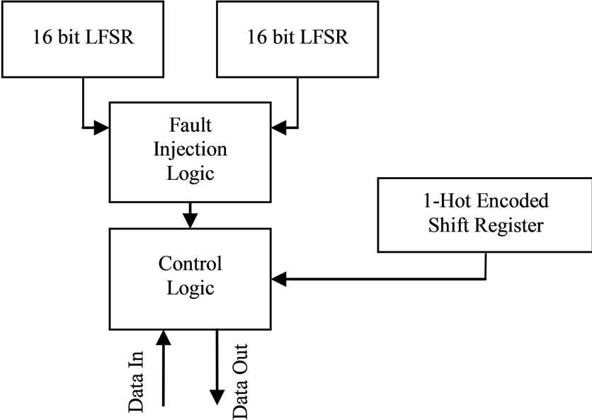
Figure 1. Block diagram of fault injection system.
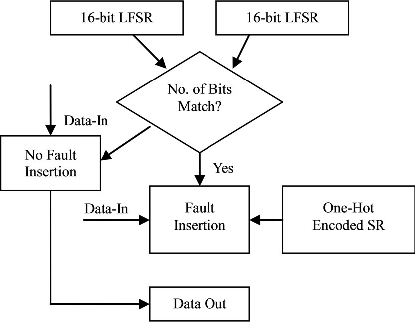
Figure 2. Basic flow chart of data through system during transient fault injection.
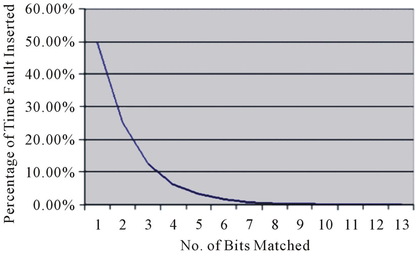
Figure 3. Percentage on the left is the percent of time a fault is inserted in the system.
be different in order to produce two different pseudorandom binary sequences.
Certain easy to use control settings are employed in order to insert a stuck-at-0 or stuck-at-1 fault at a location selected by the user. Bits can be targeted easily with permanent injection by means of the StuckAtBit and StuckAtValue in the injection block. StuckatBit is the location of the permanent fault and StuckAtValue is the logic value of the stuck-at fault. The flow for data that will have permanent injection of a fault is shown in Figure 4.
The easiest way to accomplish control of the system is with a simple generic port map in VHDL that is used for the fault injection logic block in the system. A control code that is 4 bits wide is used in the highest level block, the control logic module, in order to let the user to change the rates of fault injection.
2.2. Fault Injection Logic Block and One-Hot Encoded Shift Register
The Fault Injection Logic block is the heart of the injection system that bears the work of incorporating data from the two LFSR’s and also the One-Hot Encoded shift register. The block monitors the control inputs to the circuit to evaluate whether it needs to perform transient or permanent fault injection in the data that is sent to it. The control code which initializes permanent fault injection is “1111”. If “1111” is sent to the injection system, the fault injection logic inserts a stuck-at fault at the location that is specified by the user (StuckAtBit) to the value (StuckAtValue) that is specified by the user. Otherwise, injection is determined to be of the transient nature. It must be made clear that the system operates differently when this “1111” is passed to it in the form of a control code. That code is the only one that uses StuckAtBit and StuckAtValue.
Other control codes are for transient injection and range from “0001” ® 50% injection to “1110” ® < 0.01% injection. A control code of “0000” is 0% fault
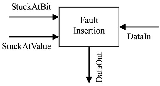
Figure 4. Data flow for permanent fault injection.
injection while a control code of “1111” is 100% fault injection. The control code is used to control the point in time at which the fault is injected. By incrementing this control code by “1” for each code, fault injection is dropped by 1/2 from the previous rate.
In order to determine the bit on which a fault will be inserted during transient fault injection, a one-hot encoded shift register is used. Every clock cycle, a logic “1” is shifted through a data word that is the length of the data word sent to the injection system. The purpose of the “1” is to determine on which bit the fault will be injected. When the control logic has seen that a fault is to be injected, it views the data output word of the one-hot encoded shift register. On the bit which is a “1” the control logic flips the bit in the data word.
The Fault Injection Logic block constantly monitors the output of both of the LFSR’s, determining whether a fault is to be injected or not. It also determines on which bit a fault will occur if more than one bit is sent to the injection system. The Fault Injection Logic block sends to the Control block the same data word that was passed into the system or a faulty data word based on whether a fault has been calculated to occur.
2.3. Control Logic for Fault Insertion
The Control logic allows the user to change rates of fault insertion during operation. It does this by operating in parallel 15 different Fault Injection Logic blocks. The output of a certain Fault Injection Logic block is directed to the output of the injection system by multiplexing the 16 total different signals to the output of the injection block based on the 4-bit wide control code, as discussed in the previous section. If the fault injection system is not activated, the data that is sent into the system is directed out. But if the system is active, then a fault is inserted on the data word coming into the system and directed to the data out word.
2.4. Component Instantiation
In behavioral or structural design approach within VHDL, the component instantiation is the same. With predominately behavioral design approaches being used in system design especially in describing complex state machines, it is not possible to predict the structure of the circuit generated by the synthesis tool. Therefore, a generic instantiation block as shown in Figure 5 is employed in the proposed fault injection technique.
In Figure 5 DataLength is the length of the primary input or internal signal on which a fault will be injected. It is just a positive integer that is needed in order for the fault injection system to operate, and should be the same as the number of bits that are contained in a signal or primary input that is being fed to the system for fault injection. For example, for a single bit that is sent to the system for injection, DataLength is 1. For a 4-bit wide word whereby faults will be inserted, DataLength is 4. DataIn is the signal or primary input from the VHDL block that is calling this instantiation for which a fault will be inserted. DataOut corresponds to the output of the block that may contain a fault. Faults injected by the system are placed on the data coming from DataIn and seen on DataOut. DataIn and DataOut must be of the same width and must be DataLength bits long. Ctrl codes are 4 bits wide and range from “0000” to “1111”. “0000” corresponds to no fault injection and “1111” corresponds to permanent fault injection. Clk is a system clock that is needed to be turned on for both transient and permanent fault injection. The Reset signal resets all flip flops in the system and must be enabled for at least one clock cycle at the beginning of a simulation followed by the load signal one to two clock cycles later. Match is simply an output signal denoting a fault has occurred and enable allows the system to inject faults onto incoming data. StuckAtBit and StuckAtValue are only useful when permanent fault injection in the system with a control code of “1111”. StuckAtBit is the bit on which a permanent fault is injected, and StuckAtValue is the logic value (0 or 1) that the bit selected by StuckAtBit is set to.
2.5. Injection Block Placement
The proposed fault injection system is able to inject faults into both combinational and sequential parts of VHDL descriptions and into behavioral or structural VHDL coding. With predominately behavioral design
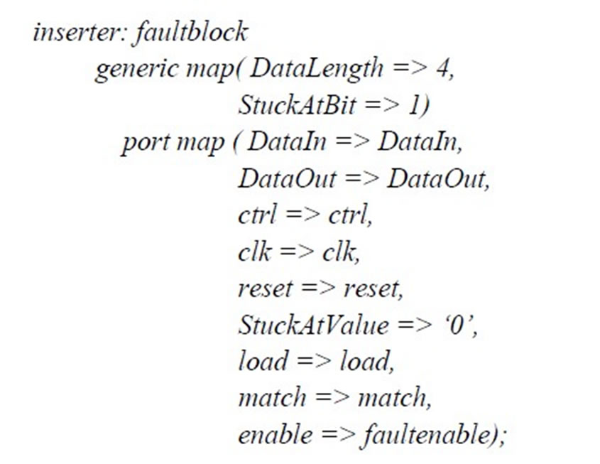
Figure 5. Generic fault injection system instantiation in VHDL.
approaches being used in system design especially in describing complex state machines, it is not possible to predict the structure of the circuit generated by the synthesis tool. Since in most cases only the behavioral description of a sequential circuit is available, the ability to inject faults in the VHDL description of the sequential circuit is imperative in order to have the capability to assess the controllability and observability of the eventual circuit resulting from the VHDL description.
The fault injection block is not meant to be able to inject faults on every signal within a VHDL description, but to reach as many low-level VHDL blocks containing primary inputs and outputs, internal signals therein as possible.
3. Fault Injection System in Practice
The application of the proposed fault injection system is illustrated through several examples. The VHDL coding and compilation in the following examples utilized the Xilinx Foundation 5.1.03i, and the simulation was performed in ModelSim XE II 5.6a. In order to write VHDL in the in the Xilinx Foundation, a specific FPGA had to be chosen; the FPGA XC2V500-4FG456C was selected for this purpose.
3.1. Transient Fault Injection in Online Testable Systems
To illustrate the use of fault injection in an on-line testable circuit, the fault injection block must be inserted into a VHDL block that is meant to be self-checking. A self-checking circuit can determine whether a fault has propagated to an output data word or not. Thus, a coding system must be employed to accomplish the self-checking aspect of the circuit and a checker that accepts coded data. For this example, a 2-out-of-4 code is used for the method of data encoding. In other words, for every 4-bit word of data that is going through the system, 2 bits in each word are 1s and the other two are 0s. The fault injection block is placed as shown in Figure 6. Subsequently, data is fed from the fault injection block to the 2-out-of-4 code checker which is shown in Figure 7. When Z1 Z2 = 01 or 10, the circuit under test is fault-free, where as Z1 Z2 = 00 or 11 indicates the presence of a fault.
The 2-out-of-4 Code Generator circuit is assumed to have 3 inputs (I1, I2, I3) and a 2-out-of-4 code as the output (O1, O2, O3, O4). The sum of products notation for the example circuit is:
O1 = ∑ (0, 3, 5, 6)
O2 = ∑ (1, 3, 4, 6)
O3 = ∑ (2, 4, 5, 7)
O4 = ∑ (0, 1, 2, 7)
The VHDL code for the circuit is shown below:
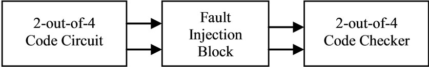
Figure 6. Placement of fault injection block in VHDL code.
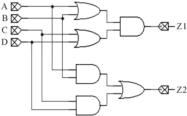
Figure 7. 2-out-of-4 checker [9].
library IEEE;
use IEEE.STD_LOGIC_1164.ALL;
use IEEE.STD_LOGIC_ARITH.ALL;
use IEEE.STD_LOGIC_UNSIGNED.ALL;
library work;
use work.lfsr_pkg.all;
entity test1 is
Port (DataOut: out std_logic_vector(3 downto 0);
clk,reset,load,faultenable : in std_logic;
ctrl : in std_logic_vector(3 downto 0);
CircuitIn : out std_logic_vector(2 downto 0);
match : out std_logic;
fault : out std_logic;
Z1,Z2 : out std_logic);
end test1;
architecture Behavioral of test1 is
signal i : std_logic_vector(2 downto 0);
signal DataIn : std_logic_vector(3 downto 0);
signal subdata : std_logic_vector(3 downto 0);
begin
-- The LFSR serves the function of feeding inputs to the
-- circuit so it will not have to be done manually in the
-- simulator
LFSR1: LFSR_GENERIC
generic map (Width => 3)
port map (clock => clk
reset => reset
load => load
seed => “101”
parallel out => i);
CircuitIn <= i;
-- DataIn(3) = O1, DataIn(2) = O2, DataIn(1) = O3, DataIn(0) = O4
DataIn(3) <= (NOT i(0) AND (i(1) XNOR i(2))) OR (i(0) AND (i(1) XOR i(2)));
DataIn(2) <= i(0) XOR i(2);
DataIn(1) <= (NOT i(2) AND (i(0) XOR i(1))) OR (i(0) AND i(2));
DataIn(0) <= (NOT i(0) AND NOT i(1)) OR (i(1) AND (i(0) XNOR i(2)));
-- Fault insertion block instantiation
inserter: faultblock
generic map(DataLength => 4,
StuckAtBit => 0)
-- The value for StuckAtBit does not matter in this case
-- because a transient fault is going to be injected, thus
-- letting the injection system handle when and where the
-- fault occurs
-- The 4 indicates the length of the data word for which a
-- fault shall be injected
port map (DataIn => DataIn,
DataOut => subdata,
StuckAtValue => ‘0’,
-- StuckAtValue does not matter in this case because
-- once again, the system in transient injection is handling
-- the location and what the fault will be
ctrl => ctrl,
-- Set ctrl anywhere between “0001” and “1110” for
-- transient fault injection
-- If ctrl is used as an input to the circuit, it can be changed
-- during operation or it can be set manually within the
-- injection block (ctrl => “0001”)
clk => clk
reset => reset
load => load
enable => faultenable);
DataOut <= subdata;
-- 2 out of 4 checker Z1 <= (subdata(0) OR subdata(1)) AND (subdata(2) OR subdata(3));
Z2 <= (subdata(0) AND subdata(1)) OR (subdata(2) AND subdata(3));
end Behavioral;
Figure 8 shows the simulation results of the 2-out-of-4 encoder operating at 100 MHz without fault injection occurring. The circuit inputs are generated by a 3-bit linear feedback shift register (LFSR) and are fed directly to the circuitry described above in O1, O2, O3, & O4. The resulting 2-out-of-4 code words are verified by the code checker as shown in Z1 and Z2.
Figure 9 shows simulation results with the fault inject-
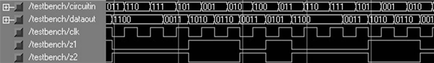
Figure 8. Example circuit for online testing without fault injection.

Figure 9. Example circuit for online testing with transient fault injection.
tion block turned on; the control code is set at 0001 i.e. the rate of fault appearance is 50%. As can be seen in the diagram for certain input combinations Z1 and Z2 are either 00 or 11. After a few clock cycles, fault insertion stops briefly to allow normal operation. This makes Z1 and Z2 to become 01 or 10. Towards the end of the diagram Z1 and Z2 become 11 and then 00 indicating the presence of a fault in the data word. This can be verified by observing the “dataout” word which is producing a non-code word.
3.2. Permanent Fault Injection in an Off-Line Testing Environment
To further illustrate the functionality of the system, an example showing permanent injection of a single stuck-at fault is provided. The test pattern generator in this case is a 3-bit LFSR. The control code is set at 1111.
There is no on-line checker in this case, the outputs need to be observed to ascertain the effect of the stuckat-1 fault being introduced on the 0-bit in the data word. The fault injection block is shown in Figure 10.
Figure 11 shows the simulation results in the absence of a fault. The expected outputs can be observed on the Datout line. From the simulation results in Figure 12, it can be concluded that the circuit is operating with a stuck-at-1 fault on bit 0 in the data word, as indicated in the specifications of the injection block in Figure 10. It should be noted that that the fault injection block of Figure 10 can insert either a transient or a permanent fault simply by changing the control code even during normal operation. However, the location of the permanent cannot be changed during operation.
4. Transient and Permanent Fault Injection in a Sequential Circuit
The fault insertion technique proposed in [5] considered combinational logic circuits only With predominately behavioral design approaches currently being used in system design especially in describing complex state
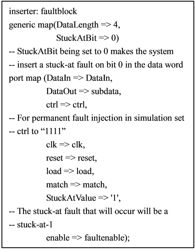
Figure 10. Fault injection block for offline testing example.
machines, it is not possible to predict the structure of the circuit generated by the synthesis tool. Since in most cases only the behavioral description of a sequential circuit is available, the ability to inject faults in the VHDL description of the sequential circuit is imperative in order to have the capability to assess the controllability and observability of the eventual circuit resulting from the VHDL description. The fault injection block is not meant to be able to inject faults on every signal within a VHDL description, but to reach as many low-level VHDL blocks containing primary inputs and outputs, internal signals therein as possible
If Z1, Z2 = “01” or “10”
® Circuit is behaving normally
If Z1, Z2 = “00” or “11”
® Circuit is operating with a fault
For sequential circuits, the states must be set outside a process statement in order for the injection system to
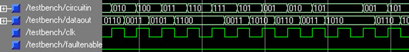
Figure 11. Example circuit for offline testing without fault injection.

Figure 12. Example circuit for offline testing with permanent fault injection.
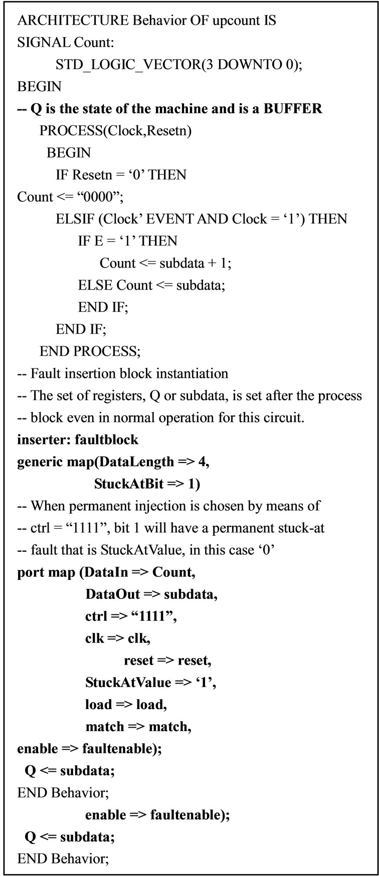
Figure 13. Up-counter with injection system in place.
operate. The process statement may however contain a signal representing the state of the machine. The signal that identifies the new state of the machine is used in the DataIn assignment in the injection block. The new state of the machine is on DataOut. The new state may or may not contain an injected fault. The component instantiation for the system cannot be implemented within a process statement. An example sequential circuit that includes a fault injection block is shown in Figure 13. Figure 14 shows the simulation results of the sequential circuit described in Figure 13 operating under normal conditions. Figure 15 shows the circuit operation with a 50% fault injection rate. As can be seen in the diagram the counter is going through erroneous state transitions. Figure 16 shows the circuit operation with permanent fault injection for a stuck-at-1 on bit 0 of the counter registers. It should be clear from the diagram that the circuit states are erroneous.
5. Conclusion
A fault injection technique that enables designers the access to a VHDL package to insert a fault on any signal within the block of a VHDL code, has been presented. It allows the injection of transient faults randomly across a data word, and allows the insertion of a permanent fault at any chosen point in a data word. A number of examples are provided to illustrate the use of the proposed fault injection system in onand off-line testing environments for both combinational and sequential circuits. A major advantage of the proposed approach is that the fault insertion process is significantly simpler than other currently available approaches. Since the fault insertion block is included in a package, much like a library in other forms of programming, only a simple call at the beginning of the VHDL description and a component instantiation is needed to activate the insertion mechanism.
6. Acknowledgements
This work was supported in part by the National Science

Figure 14. Sequential Circuit (Counter) operating normally.

Figure 15. Sequential Circuit (Counter) operating with 50% fault injection.

Figure 16. Sequential Circuit (Counter) operating with stuck-at-1 on bit 0.
Foundation, USA under Grant 0925080.
REFERENCES
- A. Benso and P. Prinetto, “Fault Injection Techniques and Tools for Embedded Systems Reliability Evaluation,” Kluwer Academic Publishers, Holland, 2003.
- P. K. Lala, “Self-Checking and Fault Tolerant Digital Design,” Morgan Kaufmann Publishers, Waltham, 2001.
- J. Gracia, L. Saiz, J. C. Baraza, D. Gil and P. Gil, “Analysis of the Influence of Intermittent Faults in a Microcontroller,” 11th IEEE International Workshop on Design and Diagnostics of Electronic Circuits and Systems, Bratislava, 16-18 April 2008, pp. 80-85.
- L. J. Saiz, J. Gracia, J. C. Baraza, D. Gil and P. J. Gil, “Applying Fault Injection to Study the Effects of Intermittent Faults,” 7th European Dependable Computing Conference, Kaunas, 7-9 May 2008, pp. 67-69.
- S. R. Seward and P. K. Lala, “Fault Injection for Verifying Testability at the VHDL Level,” Proceedings of International Test Conference, Baltimore, 30 September-2 October, 2003, pp. 131-137.
- W. Sheng, L. Xiao and Z. Mao, “An Automated Fault Injection Technique Based on VHDL Syntax Analysis and Stratified Sampling,” 4th IEEE International Symposium on Electronic Design, Test and Applications (Delta ), Hong Kong, 23-25 January 2008, pp. 587-591.
- T. A. Delong, B. W. Johnson and J. A. Profeta III, “A Fault Injection Technique for VHDL Behavioral-Level Models,” IEEE Design & Test of Computers, Vol. 13, No. 4, 1996, pp. 24-33. doi:10.1109/54.544533
- B. Parrotta, M. Rebaudengo, M. S. Reorda and M. Violante, “New Techniques for Accelerating Fault Injection in VHDL Descriptions,” Proceedings of 6th IEEE Online Testing Workshop, Palma de Mallorca, 3-5 July 2000, pp. 61-66. doi:10.1109/OLT.2000.856613
- F. Vargas, A, Amory and R. Velazco, “Estimating Circuit Fault-Tolerance by Means of Transient-Fault Injection in VHDL,” Proceedings of 6th IEEE Online Testing Workshop, Palma de Mallorca, 3-5 July 2000, pp. 67-72. doi:10.1109/OLT.2000.856614
- N. Z. Basturkmen, S. M. Reddy and I. Pomeranz, “A Low Power Pseudo-Random BIST Technique,” Proceedings of IEEE International Conference on Computer Design: VLSI in Computers and Processors, Freiberg, 16-18 September 2002, pp. 468-473.
- A. Manzone and D. De Costantini, “Fault Tolerant Insertion and Verification: A Case Study,” Proceedings of IEEE Memory Technology Design and Testing Workshop, Isle of Bendor, 10-12 July 2002, pp. 44-48.
- R. J. Hayne and B. W. Johnson, “Behavioral Fault Modeling in a VHDL Synthesis Environment,” Proceedings of VLSI Test Symposium, Dana Point, 25-29 April 1999, pp. 333-340.
- D. G. Mavis and P. H. Eaton, “SEU and SET Mitigation Techniques for FPGA Circuit and Configuration Bit Storage Design,” Proceedings of Military and Aerospace Applications of Programmable Devices and Technologies Confenerce, Laurel, 10-12 September 2000, pp. 1-15.
- P. Civera, L. Macchiarulo, M. Rebaudengo, M. S. Reorda and A. Violante, “Exploiting FPGA for Accelerating Fault Injection Experiments,” Proceedings of IEEE Online Testing Workshop, Taormina, 9-11 July 2001, pp. 9-13. doi:10.1109/OLT.2001.937810