Circuits and Systems
Vol. 3 No. 1 (2012) , Article ID: 16630 , 8 pages DOI:10.4236/cs.2012.31011
Design of Robust Power System Stabilizer Based on Particle Swarm Optimization
1Systems Engineering Department, King Fahd University of Petroleum and Minerals (KFUPM), Dhahran, Saudi Arabia
2Electrical Engineering Department, Cairo University, Giza, Egypt
Email: msmahmoud@kfupm.edu.sa, hsoliman1@yahoo.com
Received October 11, 2011; revised November 17, 2011; accepted November 26, 2011
Keywords: Dynamic Stability; Power System Stabilizer; Static Output Feedback; Particle Swarm Optimization; Linear Matrix Inequality
ABSTRACT
In this paper, we examine the problem of designing power system stabilizer (PSS). A new technique is developed using particle swarm optimization (PSO) combined with linear matrix inequality (LMI). The main feature of PSO, not sticking into a local minimum, is used to eliminate the conservativeness of designing a static output feedback (SOF) stabilizer within an iterative solution of LMIs. The technique is further extended to guarantee robustness against uncertainties wherein power systems operation is changing continuously due to load changes. Numerical simulation ahs illustrated the utility of the developed technique.
1. Introduction
Dynamic system stability is a fundamental property of power systems that describes its ability to remain in a state of equilibrium under normal operating conditions and to regain an acceptable state of equilibrium in face of an external disturbance. It is generally observed that power system stability margins generally decrease, mainly due to Kundur [1]:
1) The restructuring of the electric power industry. Such a process decreases the stability margins due to the fact that power systems are not operated in a cooperative way anymore.
2) The inhibition of further transmission or generation constructions by economical and environmental restricttions. Consequently, power systems must be operated with smaller security margins.
3) The multiplication of pathological characteristics when power system complexity increases. These include: large scale oscillations originating from nonlinear phenomena, frequency differences between weakly tied power system areas, interactions with saturated devices, and interactions among power system controls.
Beyond a certain level, the decrease of power system stability margins can lead to unacceptable operating conditions and/or to frequent power system instability. One way to avoid this phenomenon and to increase power system stability margins is to control power systems more efficiently.
Synchronous generators are normally equipped with power system stabilizers (PSS) which provide supplementary feedback stabilizing signals through the excitation system. The stability limit of power systems can be extended by PSS, which enhances system damping at low frequency oscillations associated with electromechanical modes [2,3]. The problem of PSS design has been addressed in the literature using many techniques including, but not limited to, root locus and sensitivity analysis, adaptive control, robust control, pole placement, H∞ design, and variable structure control [4-8]. The powerful optimization tool of linear matrix inequalities is also used to enhance PSS robustness through state and output feedback [9-11]. The availability of phasor measurement units was recently exploited in [12] for the design of an improved stabilizing control based on decentralized and/or hierarchical approach. Furthermore, the application of multi-agent systems to the development of a new defense system which enabled assessing power system vulnerability, monitoring hidden failures of protection devices, and providing adaptive control actions to prevent catastrophic failures and cascading sequences of events, was proposed in [13]. Attempts to enhance power system stabilization in case of controllers' failure are given in [14-16].
The conventional PSS commonly used in practice is a dynamic output feedback, a lead controller type, with a single or double stage and uses the speed deviation ∆ω as a feedback signal. In the present work, we propose a static output feedback (SOF) controller that uses two feedback signals ∆δ, and ∆ω. The problem of SOF is treated in [17], where a quadratic matrix inequality (QMI) necessary and sufficient condition is provided. This condition is later transformed into a linear matrix inequality (LMI) sufficient condition that can be solved in an iterative fashion using an additional variable. It turns out that the results are generally conservativeness. Improvements to [17] can be found in [18].
Based thereon, this paper builds upon [17,18] and extends them further. It combines the particle swarm optimization (PSO) with LMI to solve the necessary and sufficient condition in a direct way without any additional variable, thus eliminating the conservativeness. Essentially PSO, as a powerful probabilistic search technique [19,20] is used to minimize a design variable at the upper level, whereas the LMIs resulting from the constraints of output feedback structure are solved via optimization routines provided with MATLAB’s LMI control toolbox [21]. The coordination between PSO and LMI, developed in this paper, is needed because the formulated control design is in terms of non-convex optimization problem cannot be solved by using LMI techniques alone.
The manuscript is organized as follows: Section 2 describes the problem addressed in this paper. A dynamic model of a single machine infinite bus is presented in Section 3. Next, the technical background including robust control design by LMI approach and PSO is given in Section 4. Afterwards, result validation is given in Section 5. Finally the paper is concluded in Section 6.
Notation and Facts
In this paper, W', W–1, and  will denote respectively the transpose, the inverse, and the induced norm of any square matrix W. W > 0 (W < 0) will denote a symmetric positive (negative)-definite matrix W, and I will denote the identity matrix of appropriate dimension. The symbol
  is as an ellipsis for terms in matrix expressions that are induced by symmetryFact 1: Any congruence transformation z'Wz does not change the definiteness of W.
Fact 2: [22]: For any real matrices W1, W2 and ∆(t) with appropriate dimensions and ∆'∆ ≤ I, ↔ , it follows that
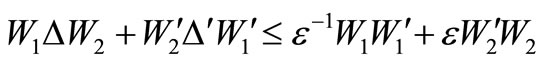 , ε > 0 where ∆(t) represents system bounded norm uncertainty.
2. Power System Model
The system under study consists of a single machine connected to an infinite bus through a tie-line as shown in the block diagram of Figure 1. It should be empha-
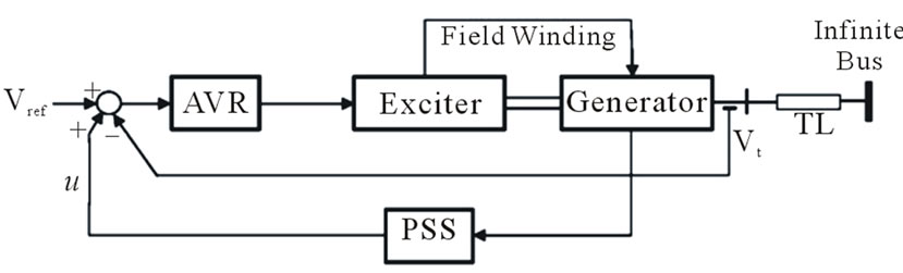
Figure 1. Power system model.
sized that the infinite bus could be representing the Thé- venin equivalent of a large interconnected power system. The machine is equipped with a static exciter. The nonlinear model of the system is given through the following differential equations [1]:
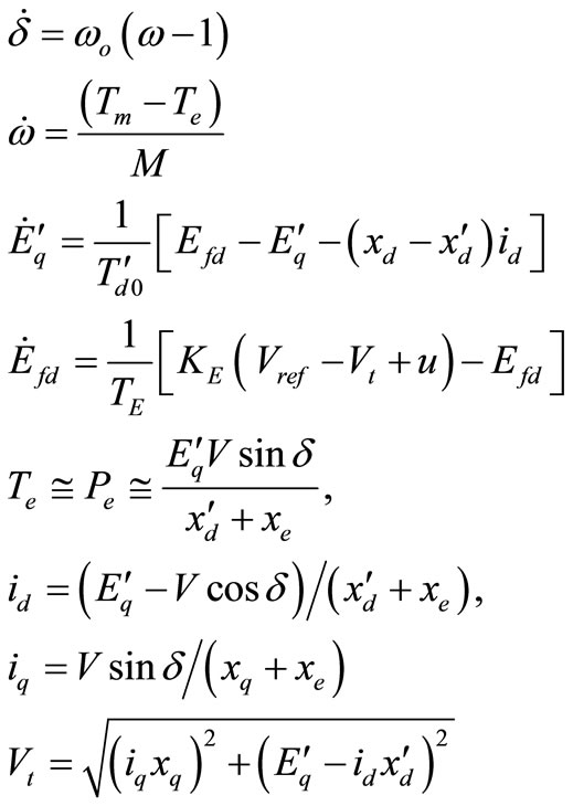
Typical data for the system under consideration, which are used in the present work, are given as follows:
• Synchronous machine parameters:

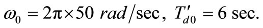
• Exciter amplifier parameters:
• Transmission line reactance:
 .
.
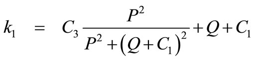
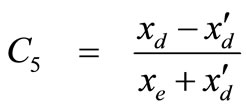
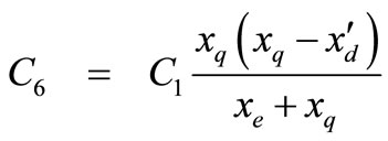
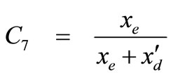
For PSS design purposes, the linearized forth order state space model around an equilibrium point is usually employed [1]. The parameters of the model have to be computed at each operating point since they are load dependent. Analytical expressions for the parameters (k1 through k6) are listed in the Appendix 1 as derived in [14-16]. The parameters are functions of the loading condition, real and reactive powers, P and Q respectively. The operating points considered vary over the intervals (0.4, 1.0), and (0.1, 0.5), respectively.
The n-dimensional linear state equation of the system under study is given by,
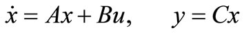 (2)
(2)
where
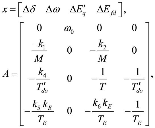 (3)
(3)
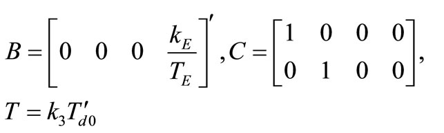
In the above equation the C matrix is so selected because ∆δ, ∆ω, can be easily calculated/measured.
System model (2) is assumed to be stabilizable via static output feedback. The static output feedback stabilization problem is to find a static output feedback u = Fy, such that the closed-loop system given by
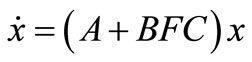 (4)
(4)
is stable, that is, with poles in the open left-half-plane.
As we all know, the closed-loop system (3) is stable if and only if there exists a P = P' > 0 such that
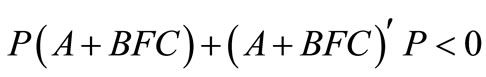 (5)
(5)
Condition (5) is a bilinear matrix inequality (BMI) which is not a convex optimal problem. An ILMI method was proposed in [17], where a new variable X was introduced such that the stability condition becomes a sufficient one when . The algorithm presented in [17], tried to find some X close to P by using an iterative method and the iterative procedure carries between P and X.
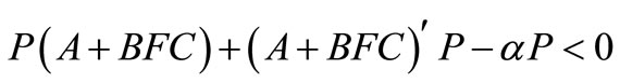
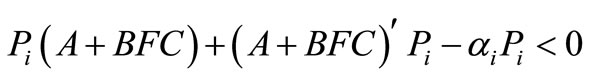
As mentioned in [17], if
 (6)
(6)
holds, the closed-loop system matrix A + BFC has its eigenvalues in the strict left-hand side of the line α/2 in the complex s-plane. If an α < 0 satisfying (5) can be found, the SOF stabilization problem is solved.
Note that (6) a nonlinear matrix inequality, difficult to solve being non convex. In [17], Inequality (6) is simplified into LMIs using an additional variable, and α is minimized iteratively till it becomes negative. Note that all eigenvalues of the closed loop matrix A + BFC are shifted progressively towards the left-half-plane through the reduction of α. A feasible solution, feedback matrix F, is thus obtained. However; it results in an only sufficient condition, causing conservativeness.
Now to represent system dynamics at different loads, system (2) can be cast in the following norm-bounded form
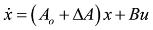 (7)
(7)
where Ao is the state matrix at the nominal load , the uncertainty in A is
 (8)
(8)
The matrices M and N being known constant real matrices, and ∆(t) the uncertain parameter matrix. The matrix ∆A has bounded nom given by , Appendix 2. It is worth mentioning that Δ(t) can represent power system uncertainties, unmodelled dynamics, and/or nonlinearities.
Table 1 gives the extreme operating range of interest, heavy and light loads, as well as the nominal load. The corresponding system matrices are given in Appendix B.
Our objective now is to study two main problems:
How to eliminate the conservativeness of [17]? How to robustify F in face of system uncertainties due to load variations?3. Problem Solution
This section gives a brief overview of control design when formulated in terms of PSO and LMI.
3.1. Particle Swarm Optimization (PSO)
For unconstrained nonlinear optimization, we have the following problem
 (9)
(9)
The existence of a solution is verified numerically by minimizing J. Such problem is solved using particle swarm optimization (PSO). Like any other optimizer, the PSO converges to a solution, if exists. Most of the traditional deterministic optimization methods have the calculation burden of gradients or Hessians. In other words, they are based on the unrealistic assumptions, e.g., unimodal, differentiable, and continuous objective function. In non-gradient conventional optimization techniques, the gradient is numerically estimated. Deterministic me-
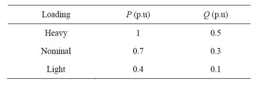
Table 1. Loading conditions.
thods can potentially converge to a local minimum instead of the global minimum. There is no criterion to decide whether a local solution is also the global solution.
Therefore, the conventional optimization methods are, in general, not able to locate or identify the global optimum. Recently, many researchers are investigating probabilistic (stochastic) global optimizers, which seem to be a promising alternative to the traditional gradientbased approaches. Several stochastic search techniques have appeared, most notably, simulated annealing, tabu search, and evolutionary routines. Upon comparing evolutionary methods, the genetic algorithm (GA) has a big computational complexity unlike PSO, which is another stochastic global optimization technique. PSO has been found robust in solving continuous nonlinear optimization problems. In addition, PSO can generate a high-quality solution with less calculation time and more stable convergence characteristic than other stochastic methods. Due to its distinct advantages as a global optimizer, PSO has been selected to tune the reliable controllers presented in this paper.
Particle swarm optimization is an evolutionary optimization technique. Such approach is biologically inspired by the natural evolution of populations to Darwin’s principle of natural selection “Survival of the fittest”. The promising optimization algorithm of PSO, Parsopoulos and Vrahatis (2004), is a multi agent search technique that traces its evaluation to the emergent motion of a flock of birds searching for food. Each bird traverses to the search space looking for the global minimum (or maximum). PSO is a computationally simple technique since it does not involve gradient calculations. Moreover, the function to be optimized does not have to be convex. PSO is a stochastic optimization technique with large number of agents having the advantage of being unlikely trapped at local minima.
While the agents in the PSO algorithm are searching the space, each agent remembers two positions. The first is the position of the best point the agent has found (selfbest), while the second is the position of the best point found among all agents (group-best). The motion of each agent is governed through the following equation:
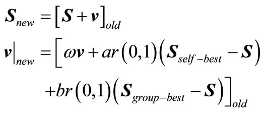 (10)
(10)
where  is a position vector of a single particle,
 is the velocity of this particle,
 are two scalar parameters of the algorithm,
 is an inertia weightr(0, 1) is a uniform random number between 0 and 1It should be noted that group-best is the best solution of all particles and self-best is the best solution observed by the current particle. A maximum velocity (vmax) that cannot be exceeded may also be imposed.
3.2. Control Design
System (2) is stabilizable if and only if there is a solution, P > 0, F, α < 0, for the following nonlinear matrix Inequality (6).
If P is given, Inequality (6) becomes linear in F, and the minimized α = α* can be easily solved by LMI control toolbox.
The idea proposed in this manuscript is to minimize α* by P generated by PSO in an outer loop of iteration as shown below.
3.3. PSO-Based Static Output Feedback Design
Step 0: Initialize the PSO by selecting randomly a vector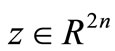 .
.
Step 1: Cast z into its matrix equivalent Z. Form P = ZZ'. In this way P = P' > 0 is generated. Set i = 1 and Pi = P Step 2: Solve the following optimization problem for F and αi.
Minimize αi subject to the following LMI constraints
 (11)
(11)
Denote  as the minimized value of αi.
Step 3: If , F is a stabilizing static output feedback gain. Stop.
If no  is found, the system cannot be stabilized by a SOF.
Step 4: Use PSO to solve the following optimization problem
 (12)
(12)
Set i > i + 1, then go to Step 1.
The above algorithm is applied to example 1 of [17]. The proposed algorithm is better than that of [18] as it stabilizes the system with less control gain, see Appendix C. This is expected as the proposed algorithm solves a necessary and sufficient condition, rather than an only sufficient of [17].
3.4. Robust Design
Since power systems undergo load changes that result in uncertainty in the state model, the SOF that robustly stabilizes the system is given by the following sufficient condition:
Theorem 1: The uncertain system (7) can be robustly stabilized if there exist P = P' > 0, F, α < 0 such that the following nonlinear matrix inequality
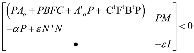 (13)
(13)
has a feasible solution.
Proof: By replacing A by Ao + ∆A in (6), it yields
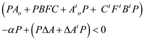 (14)
(14)
Using Fact 2, Inequality (14) is satisfied if the following equation is satisfied
 (15)
(15)
By the Schur complements [22], we can put (15) in the form (13) as desired. This completes the proof.
An algorithm for robust SOF design can be constructed similar to the previous algorithm with replacing (11) by (13).
4. Design Validation Based on Nonlinear Model
4.1. SOF-PSS
Applying the proposed algorithm, Sec 3.3, to the linearized power system model at heavy load, Appendix B, and the results are summarized as:
• Controller matrix F = [–0.2013 – 4.3512]
• α* = –0.2689
• Closed-loop eigenvalues = {–0.42814 ± i 6.2841
• –13.019, –6.5878}
The minimization of α* via PSO is shown in Figure 2. Since power system operators generally welcome the damping of transient oscillations following small distur-
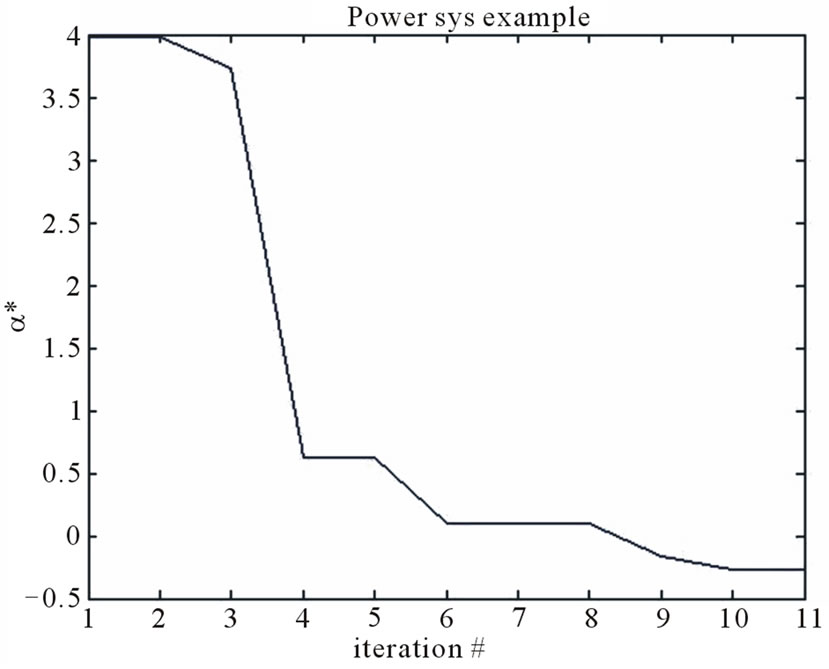
Figure 2. α* vs. iterations.
bances within a settling time of 10 - 15 sec [23], or equivalently the closed loop eigenvalues should lie to the left of the vertical line –0.3; the proposed algorithm is run till this objective is satisfied.
The proposed controller tested is on the nonlinear model (1), at the heavy load. It is assumed that the mechanical torque input undergoes a step change increase of 0.1 pu. The system is subject to a large disturbance at t = 3 s, a three-phase to ground fault occurs for 100 ms. The system without a PSS is unstable at this point, see Figure 3(a). On the other hand, the proposed stabilizer successfully suppresses and damps the oscillations in almost 7 s, see Figure 3(b).
The success of the proposed PSS, which is designed based on a linearized model, to stabilize the original nonlinear system follows from the Lyapunov indirect theorem. According to that theorem, the behavior of the originnal nonlinear system is similar to its linearized approxi-
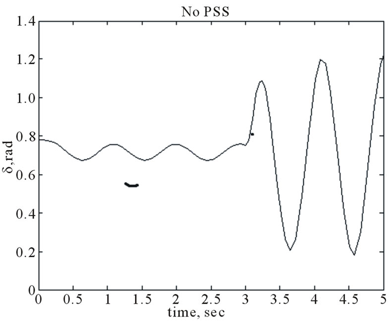 (a)
(a)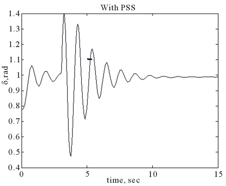 (b)
(b)
Figure 3. Time response of the nonlinear model of SMIB with and without PSS. (a) Without PSS; (b) With PSS.
mation provided that none of the eigenvalues lies on the imaginary axis.
4.2. Robust SOF-PSS
The algorithm described in Subsection 3.3 is applied find a robust SOF_PSS against the variation of power system operation;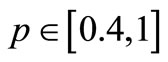 , and
, and  respectively. The results are: F = [–0.1797 –6.1133], and α* = –0.4231. The minimization of α* vs. iterations are shown in Figure 4.
Out of the aforementioned power system operating range, the point P = 0.8 p.u, and Q = 0.3 p.u is selected to show the effectiveness of the proposed design. For 0.1 p.u. step increase in mechanical power, simulation results of' a large disturbance are shown in Figure 5. At t = 3 s, a three-phase to ground fault occurs for 100ms. The proposed stabilizer succeeds to damp the disturbance within 5 sec.
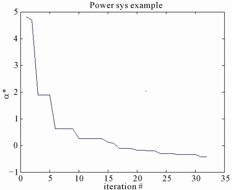
Figure 4. α* vs. iterations, robust SOF-PSS.
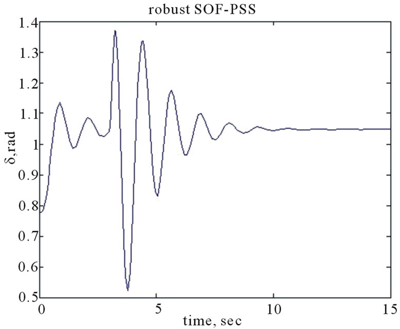
Figure 5. Performance of proposed robust stabilizer for 0.1 step increase in mech. power and the system undergoes a 3-phase to ground fault at infinite bus for 100 ms.
5. Conclusion
In this paper, a new algorithm is presented to solve a necessary and sufficient condition to stabilize linear timeinvariant systems via static output feedback. The iterative algorithm combines the PSO and LMI. The algorithm is effective and convergent. The numerical procedure may be useful to solve this kind of bilinear matrix inequality problem. In this respect, the crucial part is to obtain an iterative condition. The proposed PSO-ILMI algorithm has low dimension because no additional variable is imposed. The algorithm can be applied to PID, decentralized stabilizers as well. A numerical example shows that the proposed algorithm produces better result than the existing one. A sufficient condition for the design of robust static output feedback using PSO with iterative LMI has been proposed. The method obtains the PSS for the linearized model of a single machine infinite bus system. Simulation results based on a nonlinear model of the power system confirm the ability of the proposed compensator to stabiles the system over a wide range of operating points.
6. Acknowledgements
This work is supported by the deanship of scientific research (DSR) at KFUPM through research group project RG1105-1.
REFERENCES
- P. Kundur, “Power System Stability and Control,” McGraw Hill, New York, 1994.
- G. Guo, Y. Wang and D. Hill, “Nonlinear Output Stabilization Control for Multi-Machine Power Systems,” IEEE Transactions on Circuits and Systems, Vol. 47, No. 1, 2000, pp. 46-53. doi:10.1109/81.817388
- Z. Qu, J. Dorsey, J. Bond and J. McCalley, “Application of Robust Control to Sustained Oscillations in Power Systems,” IEEE Transactions on Circuits and Systems, Vol. 39, No. 2, 1992, pp. 470-476.
- R. You, H. J. Eghbali and M. H. Nehrir, “An Online Adaptive Neuro-Fuzzy Power System Stabilizer for Multimachine Systems,” IEEE Transactions Energy Conversion, Vol. 18, No. 1, 2003, pp. 117-125.
- H. M. Soliman, A. Elshafei, A. Shaltout and M. Morsi, “Robust Power System Stabilizer,” IEE Proceeding Generation, Transmission, and Distribution, Vol. 147, No. 2, 2000, pp. 285-291. doi:10.1049/ip-gtd:20000560
- B. Pai and B. Chaudhuri, “Robust Control in Power Systems,” Springer, New York, 2005.
- C. J. Zhu, M. Khammash, V. Vittal and W. Qiu, “Robust Power System Stabilizer Design using H∞ Loop Shaping Approach,” IEEE Transactions on Power Systems, Vol. 18, No. 2, 2003, pp. 810-818. doi:10.1109/TPWRS.2003.811176
- V. Bandal, B. Bandyopadhyay and A. M. Kulkarni, “Decentralized Sliding Mode Control Technique Based Power System Stabilizer (PSS) for Multimachine Power System,” Proceedings Control Applications, Toronto, 28-31 August 2005, pp. 55-60.
- A. I. Zecevic and D. D. Šiljak, “Control of Complex Systems: Structural Constraints and Uncertainty,” Springer, London, 2009.
- R. Gupta, B. Bandyopadhyay and A. Kulkarni, “Robust Decentralized Fast-Output Sampling Technique based Power System Stabilizer for a Multi Machine Power System,” International Journal of Systems Sciences, Vol. 36, No. 5, 2005, pp. 297-314. doi:10.1080/00207720500089440
- S. Rao and I. Sen, “Robust Pole Placement Stabilizer Design using Linear Matrix Inequalities,” IEEE Transactions Power Systems, Vol. 15, No. 1, 2003, pp. 313-319. doi:10.1109/59.852138
- I. Kamwa, R. Grondin and Y. Hebert, “Wide-Area Measurement Based Stabilizing Control of Large Power Systems—A Decentralized/Hierarchical Approach,” IEEE Transactions Power Systems, Vol. 16, No. 1, 2001, pp. 136-153. doi:10.1109/59.910791
- C. Liu, J. Jung, G. T. Heydt and V. Vittal, “The Strategic Power Infrastructure Defense (SPID) System,” IEEE Control System Magazine, Vol. 20, No. 1, 2000, pp. 40- 52.
- H. M. Soliman, M. Morsi, M. F. Hassan and M. Awadallah, “Power system reliable stabilization with actuator failure,” Electric Power Components and Systems, Vol. 37, No. 1, 2009, pp. 61-77. doi:10.1080/15325000802322020
- H. M. Soliman, H. E. Ehab, E. H. E. Bayoumi and M. A. Awadallah, “Reconfigurable Fault-Tolerant PSS and FACTS Controllers,” Electric Power Components and Systems, Vol. 38, No. 10, 2010, pp. 1446-1468. doi:10.1080/15325001003735200
- H. M. Soliman, A. Dabroum, M. S. Mahmoud and M. Soliman, “Guaranteed-Cost Reliable Control with Regional Pole Placement of a Power System,” Journal of the Franklin Institute, Vol. 348, No. 4, 2011, pp. 884-898. doi:10.1016/j.jfranklin.2011.02.013
- Y. Y. Cao, J. Lam and Y. X. Sun, “Static Output Feedback Stabilization: An ILMI Approach,” Automatica, Vol. 34, No. 12, 1998, pp. 1641-1645. doi:10.1016/S0005-1098(98)80021-6
- Y. He and Q. G. Wang, “An Improved ILMI Method for Static Output Feedback Control with Application to Multivariable PID Control,” IEEE Transactions Automatic Control, Vol. 51, No. 10, 2006, pp. 2356-2361. doi:10.1109/TAC.2006.883029
- K. E. Parsopoulos and M. N. Vrahatis, “On the Computation of All Global Minimizes Through Particle Swarm Optimization,” IEEE Transactions Evolutionary Computation, Vol. 8, No. 3, 2004, pp. 211-220. doi:10.1109/TEVC.2004.826076
- R. Mendes, J. Kennedy and J. Neves, “The Fully Informed Particle Swarm: Simpler, Maybe Better,” IEEE Transactions. Evolutionary Computation, Vol. 8, No. 3, 2004, pp. 345-360. doi:10.1109/TEVC.2004.826074
- P. Gahinet, A. Nemirovski, A. J. Laub and M. Chilali “LMI Control Toolbox,” The Math Works Inc., Natick, 1995.
- M. S. Mahmoud, “Decentralized Control and Filtering in Interconnected Dynamic Systems,” CRC Press, New York, 2010. doi:10.1201/b10349
- J. Passerby, “Analysis and Control of Power System oscillations,” Technical Brochure 111, CIGRE, 1996.
Appendix
A. Model Parameters
 ,
,
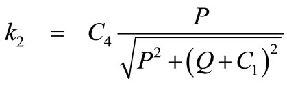 ,
,
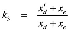 ,
,
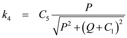 ,
,
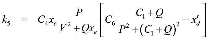 ,
,
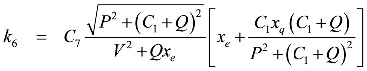 .
.
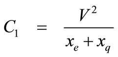 ,
,
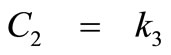
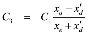 ,
,
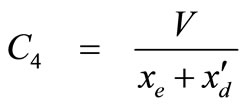
 ,
,
B. State Model
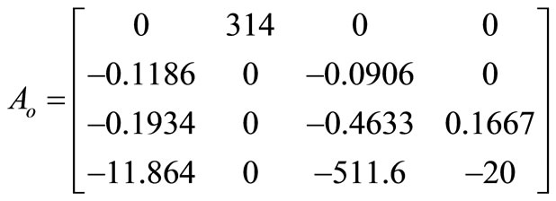
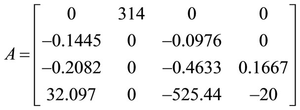
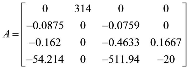
The numerical values of state space model for the three operating conditions are given as follows:
Nominal load:
Heavy load:
Light load:
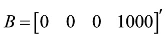
Neglecting small deviations in A, the uncertainty in A over the different loads can be approximated by a norm-bound structure M∆(t)N, M = [0, 0, 0, 6.63]', N = [6.63, 0, –2.08, 0].
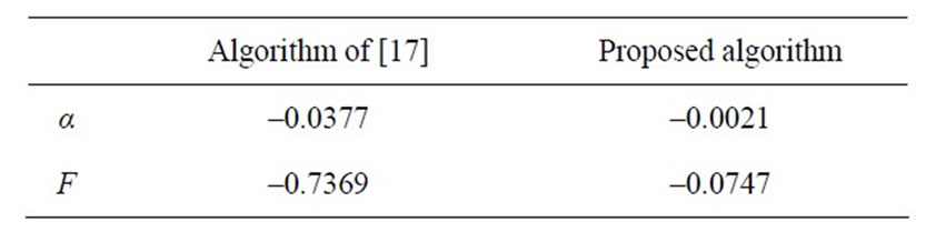
C. Comparison
Example 1 of [17] gives
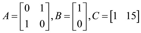
Applying the proposed algorithm, the reduction in α* vs. iteration is shown in Figure 4 and the comparison between the results of [17] and the proposed algorithm is shown below.
It is clear the superiority of the proposed algorithm over that of [17] as it stabilizes the system with less controller gain.