Energy and Power Engineering
Vol. 4 No. 4 (2012) , Article ID: 20216 , 9 pages DOI:10.4236/epe.2012.44035
Direct Torque Control Strategy of an Induction-Machine-Based Flywheel Energy Storage System Associated to a Variable-Speed Wind Generator
Research Unit on Study of Industrial Systems and Renewable Energies, National Engineering School of Monastir, Monastir, Tunisia
Email: med.mansour@yahoo.fr
Received February 14, 2012; revised March 20, 2012; accepted April 5, 2012
Keywords: VSWG; FESS; IM; DTC; DC Bus Voltage Control; Power Flow
ABSTRACT
The flywheel energy storage systems (FESSs) are suitable for improving the quality of the electric power delivered by the wind generators and for helping these generators to contribute to the ancillary services. Presently, FESSs containing a flux-oriented controlled (FOC) induction machine (IM) are mainly considered for this kind of application. This paper proposes the direct torque control (DTC) for an IM-based FESS associated to a variable speed wind generator (VSWG), and proves through simulation results that it could be a better alternative.
1. Introduction
The actual decentralized electricity sources cannot participate in the ancillary services of the power grid (voltage and frequency control, black start, and islanding operation). From the viewpoint of the power grid, these sources are like negative charges, i.e., they do not consume the electric energy but generate it, without participating in the ancillary services [1]. The mains voltage and frequency control is always reported to the classical generators. Hence, the penetration rate of the decentralized electricity production is restricted in order to keep the power grid’s stability. This is particularly right for the renewable energy sources, whose primary energy source is very fluctuant and unpredictable. The wind generators belong to this category of energy sources, and to give them the possibility to participate in the ancillary services, a generating system, which is able to feed isolated loads or to be integrated in the network, has to be considered.
In order to reach these objectives, an Energy Storage System (ESS) is needed for controlling the power flow between the wind generator and the power grid [2,3]. In fact, the ESS can contribute to the energy balance between the production and the consumption. It provides the energy in case of consumption deficiency and accumulates it at high wind speeds for which the energy request is reduced [4].
Due to the important fluctuation of the wind, conventional electrochemical batteries are not suitable [5]. They cannot support the number of required cycles nor to store a significant quantity of energy in a restricted volume [6]. The storage system must have a high dynamics in order to operate in real time, in function of the generated and consumed power fluctuations, respectively. In the last years, flywheel energy storage systems (FESSs) have been rediscovered by the industrials due to their advantages in comparison with other ESSs [7,8]. They are well appropriated because of their characteristics: high dynamics, good efficiency, long lifetime (similar to the wind generators) and ecological system [7]. The FESSs constitute short-term storage systems, which are generally sufficient to improve the electric power quality. [9, 10] show that the FESS offers an interesting solution to adapt the production to the consumption. In this paper, a FESS associated to a variable-speed wind generator (VSWG) is studied. By means of power electronic converters, the energy generation and storage systems can be connected to the DC bus in order to control the power flow from the VSWG to the isolated loads. In such a configuration, the FESS ensures the DC bus voltage control [11,12], thus contributing to the generation/consumption balance of energy.
The FESS considered for this application contains a lows-peed flywheel and a classical squirrel-cage induction machine (IM). The IM operates in the flux-weakening region, thus allowing operation at the rated power. Until the present time, only the field-oriented control (FOC) has been considered for this type of FESS [2,11, 13]. In this paper, we propose a different control method of the FESS i.e. the direct torque control (DTC). In [14-16], good comparisons between FOC and DTC are given, but only the motoring operation mode at the rated flux is considered. The application of the DTC to the IM of the FESS involves two aspects: 1) the IM must operate in the flux-weakening region and 2) it must change rapidly and many times between the motoring and generating operation modes. In other words, the IM is always operating in the transient conditions. The steady-state operation is inexistent in this application. This paper will show that the DTC can satisfy these requests.
The proposed control system is then simulated using MATLAB-SIMULINK. The obtained results are presented and discussed to demonstrate the performance of the global system.
2. Studied System
The system studied is constituted of a permanent-magnet synchronous generator (PMSG)-based VSWG, an IMbased FESS, power converters (rectifiers/inverters), as shown in the Figure 1. The FESS is controlled by DTC Technique. The goal of the system is to provide a constant power and voltage to the isolated load connected even if the flywheel speed varies. This can be achieved mainly by the control of the DC bus voltage at a constant value and the flywheel energy storage system participate to maintain the power of the load constant as long as the wind power is sufficient.
The study focuses on the control strategy, efficiency and dynamic performance of the FESS associated to a VSWG.
3. Modeling of the FESS
The FESS, as shown in Figure 1, comprises a flywheelan IM and a converter 2 (rectifier/inverter), which controls the speed of the flywheel and therefore the exchanged power.
3.1. Flywheel Modeling
The energy stored in the flywheel depends on the square of the rotational speed [7], for a given inertia, as represented as follow:
 (1)
(1)
with Jf (kg∙m2) and Ωf (rad/s) are the inertia moment and the speed of the flywheel, respectively.
To calculate the wheel inertia, we consider a power required during Δt time. In fact, to store the rated power of the IM Pn-IM during Δt, the energy ΔE is then necessary such as:
 (2)
(2)
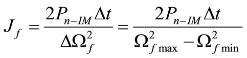
Combining Equations (1) and (2), we define the necessary value of the wheel inertia as:
 (3)
(3)
Ωfmax and Ωfmin represent the maximal speed limit and the minimal speed limit of the flywheel, respectively. Δt is then the storage period. This limit must be respected otherwise we risk to deteriorate the flywheel energy storage operation [17].
3.2. Mechanical Shaft Modeling
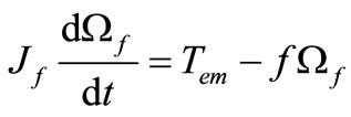
The evolution of the mechanical speed of the IM-based FESS can be easily determined using the dynamic equation. The simplified model of this equation is given by:
 (4)
(4)
where Tem (N∙m) is the electromagnetic torque and f (N∙m∙s∙rad−1) is a viscous friction coefficient.
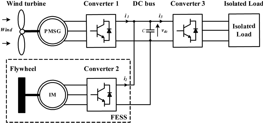
Figure 1. Configuration of the studied generation system.
3.3. IM Modeling
The model generally used in the cage IM is the model of Park [18]. In our approach, we adopt the d-q model of the IM expressed in the stator frame noted by (αβ). The currents and the flux and are given by the following equations:
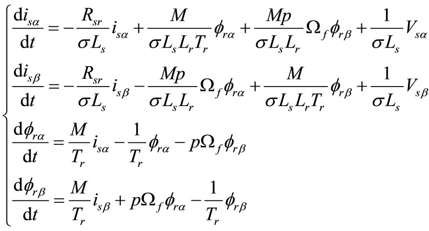 (5)
(5)
where:
Ls, Lr: are the cyclique-propre inductances of the stator and of the rotor (H);
M: is the mutual inductance between the stator and the rotor (H);
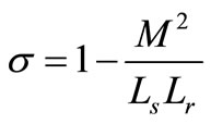 : is the dispersion coefficient of the machine;
Rs, Rr: are the resistances of the stator and rotor (Ω),
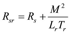 (Ω);
(Ω);
 : is the rotor speed constant;
 ,
, : are the α-β components of the rotor flux respectively (Wb);
isα, isβ: are the α-β components of the stator currents respectively (A);
vsα, vsβ: are the α-β components of the stator voltages respectively (V);
p: is the number of pairs of poles.
The electromagnetic torque is given by:
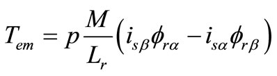 (6)
(6)
4. Control of the FESS Associated to a VSWG
4.1. Control Strategy for the FESS
The wind generators are considered as negative charges for the power grid, because they do not consume the electric energy but generate it without participating to the ancillary services. It is well known that the wind speed is very fluctuant, and for this reason, the wind generator will deliver a variable electric power [9].
To overcome this drawback, two methods are available:
1) Acting on the mechanical system, using the pitch or stall-controlled wind turbines in order to deliver a constant power to the wind generator [19,20];
2) Acting on the electric system, associating an energy storage system with the wind generator in order to regulate the electric power delivered into the power grid [2, 11].
The first method gives acceptable results when connecting the wind generators at a strong power grid, but if the wind generator supplies a weak grid or an isolated load, the power fluctuations can still be questionable. That is the reason for choosing the second method in the power regulation. An energy buffer is needed in order to make a good power regulation [2,11].
Figure 2 gives a graphic explanation of the control principle of the FESS. The FESS has two functions: to regulate the DC bus voltage and to regulate the power flow toward the load [21].
From Figure 1, the evolution of the DC bus voltage can be deduced:
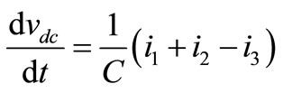 (7)
(7)
To regulate the DC bus voltage, a PI voltage controller is used and gives the value of the power ΔP required for maintaining this voltage at the reference value vdc-ref.
To control the speed of the flywheel energy storage system we must find reference speed which with the system must turn to ensure the energy transfer required at each time. The reference speed can be determinate by the reference energy. The power assessment of the overall system is given by [21]:
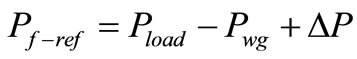 (8)
(8)
where Pf-ref is the reference value of the active power exchanged between the FESS and the load, Pload is the

Figure 2. Graphic representation of the FESS control strategy.
load demand power and Pwg is the optimal active power generated by the VSWG.
If Pf-ref is positive, means that exists energy in excess which can be stored. If Pf-ref is negative, a lack in energy exists and it will be replaced by the stored energy.
4.2. DTC for the FESS IM
4.2.1. DTC Principle
The IM is controlled by DTC Technique. DTC method has been first proposed for induction machines. DTC technique introduced by Takahashi and Noguchi [22] for low and medium power application and DTC technique introduced by Depenbrock [23] for high power application are popular in industry. DTC strategy is quite different from that of the FOC or vector control, which does not need complicated coordination transformations and decoupling calculation [24].
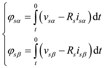
The DTC technique is based on the direct control of the stator flux and torque. In this technique, the supply voltage and stator current are sampled. In order to control the induction motor, stator flux on the stationary reference axes αβ are calculated. It is possible to ignore the sampling of the voltage and only measure the current. If vs = vsα + jvsβ and is = isα + jisβ are the input voltage and current vectors respectively, the stator flux vector can be estimated as follows:
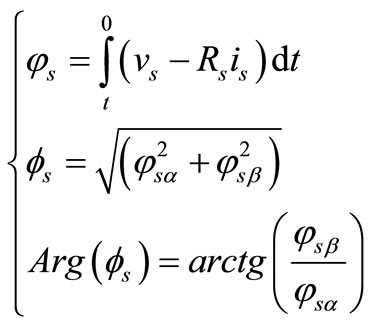 (9)
(9)
where
 (10)
(10)
φs is the stator flux vector, Φs is the amplitude of the stator flux and Rs is the stator resistance.
The stator-voltage space vector vs is computed using the dc-link voltage vdc and the inverter switch gating signals Sa, Sb, and Sc:
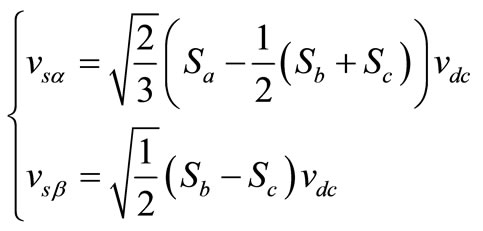 (11)
(11)
Si = 1 the phase i is connected to the supply positive polarity Si = 0 the phase i is connected to the supply negative polarity The stator-current space vector is derived from the measured currents ia, ib, and ic:
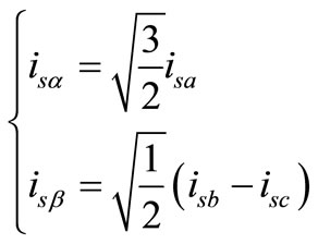 (12)
(12)
The electromagnetic torque Tem of the motor can be evaluated as follows:
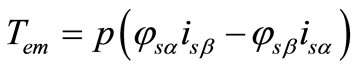 (13)
(13)
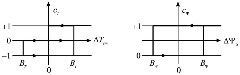
The basic model of the conventional DTC IM scheme is shown in Figure 3. The magnitude of stator flux and electric torque calculated are compared with their reference values in the hysteresis comparators shown in Figure 4 and then the outputs of the comparators are fed to a switching table to select an appropriate converter voltage vector. The switching table shown as Table 1 determine the voltage vector to apply based on the position of the stator flux and the required changes in stator flux magnitude and torque [25]. The selected voltage vector will be applied to the IM at the end of the sample time. In voltage source converter, there are six equally spaced voltage vectors having the same amplitude and two zero voltage vectors. Figure 5 illustrates the voltage vectors in every sector, which are selected from the eight possible switches configurations, using the look-up table given in Table 1.
In DTC, torque and flux are controlled independently by selecting the optimum voltage space vector for entire switching period and the errors are maintained with in the hysteresis band [26]. In conventional DTC, only one vector is applied for the entire sampling period. So for small errors, the machine torque may exceed the upper/ lower torque limit. Instead by using more than one vector with in the sampling period torque ripple can be reduced. The slip frequency can be controlled precisely by inserting zero vectors [27]. For the small the hysteresis band, frequency of operation of PWM converter could be very
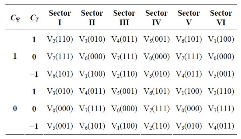
Table 1. Switching table.

Figure 3. FESS control scheme using DTC for the IM.
 (a) (b)
Figure 4. Hysteresis comparator (a) Stator flux; (b) Torque.
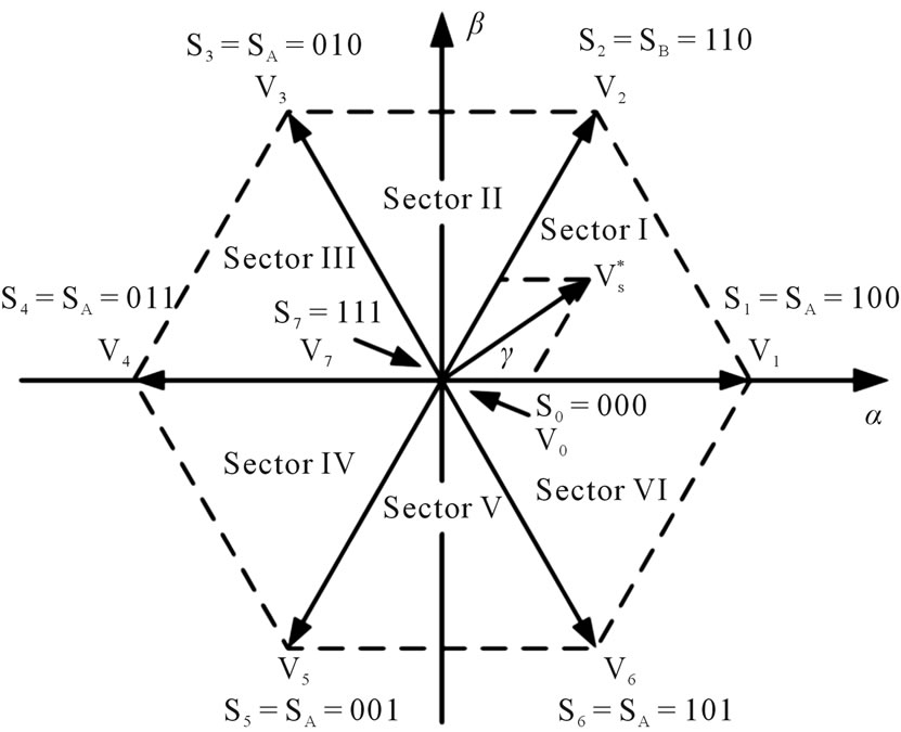
Figure 5. Voltage vectors.
high. The switching frequency always varies according to the width of hysteresis band.
The power reference value Pf-ref allows us to determine the flywheel speed reference value controlled via converter 2 (Figure 1). The flywheel reference rotational speed can be deduced from (1):
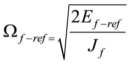 (14)
(14)
The energy reference value Ef-ref is determined from the power reference value:
 (15)
(15)
Ef0: is the initially flywheel stored energy.
A PI controller is used to determine the reference torque, based on the difference between the reference and instantaneous speeds of the motor.
4.2.2. Flux Reference Determination
Since the maximum speed of the flywheel is 3000 rpm, whereas the base speed of the IM is 1500 rpm, the FESS IM must operate in its flux-weakening region in order to reach the maximum speed of the flywheel. In this region, the rated power of the IM is still available from 1500 to 3000 rpm.
Flux-weakening control of the IM is usually accomplished by regulating the stator flux according to the following control law [28]:
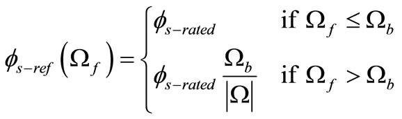 (16)
(16)
where Ωb is the IM base speed and  is the IMrated stator flux.
The control scheme of the FESS IM is presented in Figure 3.
5. Simulation Results and Discussions
We present the simulations results, using numerical simulations carried under the Matlab-SIMULINK, of the FESS associated to a VSWG. Simulation is made with a wind power profile which provides power continuously required by the load through the FESS. Figure 6 shows the VSWG power Pwg and the load demand power Pload which equal to −1 kW.
Initially, the speed of the flywheel is 235.6 rad/s (2250 rpm).
Figure 7 shows the FESS power and its reference power. It depicts the power stored (positive) or generated (negative) by the FESS. We note that the power exchanged between the FESS and the isolated load, is very fluctuant, as the VSWG power is, which causes the flywheel to slow down/accelerate.
Flywheel speed and the reference speed are plotted in Figure 8. The rotational speed increases when the energy is transferred to the flywheel, and decreases when the flywheel is unloaded. Figure 9 gives the IM electromagnetic torque which is fluctuant, like the VSWG power, and entails the flywheel speed variations.
The FESS regulates the DC bus voltage which is well maintained at 400 V (Figure 10). Thus, the simulation results prove that a DTC-IM can satisfactorily be used in FESS associated to a VSWG.
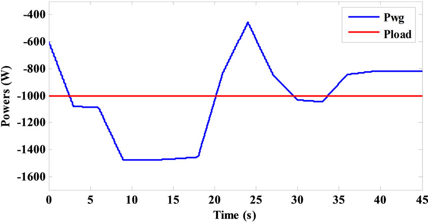
Figure 6. VSWG power Pwg and load power Pload.
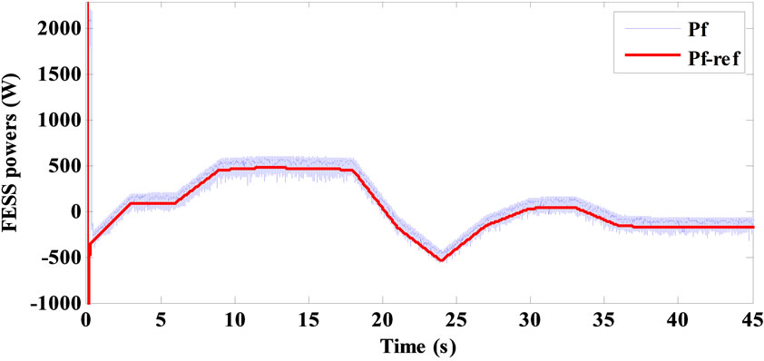
Figure 7. FESS powers Pf-ref and Pf.

Figure 8. Flywheel speed Ωf-ref and Ωf.
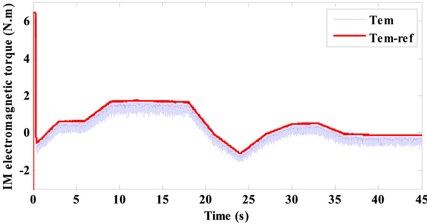
Figure 9. IM electromagnetic torque Tem-ref and Tem.

Figure 10. DC bus voltage vdc.
It can be shown in Figure 11 that the reference stator flux and the estimated stator flux are almost confused. We note also that the IM always operates in the fluxweakening region and the magnitude of its stator flux changes as a function of speed.
The effect of the discrete hysteresis controller can be shown in Figures 7, 9 and 11; the ripples of FESS power, IM electromagnetic torque and stator flux, are irregulars. This can be explained by the DTC control method where the stator currents are not directly controlled, but they are varying as a function of the selected voltage vector.
The simulation stator flux trajectory is represented in Figure 12.
6. Conclusion
A contribution to improvement of the performances for
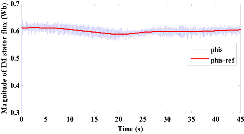
Figure 11. Magnitude of IM stator flux  and
and .
.
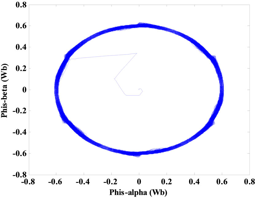
Figure 12. Stator flux trajectory.
wind energy conversions systems of VSWG associated to a FESS has been presented in this paper. A low-speed FESS, whose electric machine is a classical squirrel-cage IM, has been considered. A new DTC control strategy has been applied to the IM. This application involves two main constraints on the IM: it must operate in the fluxweakening region and it must change rapidly and many times between motoring and generating operation modes. Simulation results have shown that DTC can fulfil these requirements and proved that the DTC IM-based FESS can control the DC bus voltage and the power flow from the VSWG to the isolated load.
As compared to FOC, DTC is simpler in experimental implementation and needs less demanding controllers. It has been also proved that DTC can operate with constant switching frequency by using discrete hysteresis controllers, which are appropriate to DSP control boards.
REFERENCES
- G. Cimuca, S. Breban, M. M. Radulescu, C. Saudemont and B. Robyns, “Design and Control Strategies of an Induction-Machine-Based Flywheel Energy Storage System Associated to a Variable-Speed Wind Generator,” IEEE Transactions on Energy Conversion, Vol. 25, No. 2, 2010, pp. 526-534. doi:10.1109/TEC.2010.2045925
- F. Hardan, J. A. M. Bleijs, R. Jones and P. Bromley, “Bi-Directional Power Control for Flywheel Energy Storage System with Vector-Controlled Induction Machine Drive,” Proceedings of IEE Conference Publication, Institution of Electrical Engineers, No. 456, 1998, pp. 456-477.
- G. Cimuca, M. M. Radulescu, C. Saudemont and B. Robyns, “DTC vs FOC of an IM-Based Flywheel Energy Storage System Associated to a Variable-Speed Wind Generator,” Proceedings of the 8th International Conference on Modeling and Simulation of electrical Machine, Converters and Systems, Hammamet, 17-20 April 2005, CD-ROM.
- L. Jerbi, L. Krichen and A. Ouali, “A Fuzzy Logic Supervisor for Active and Reactive Power Control of a Variable Speed Wind Energy Conversion System Associated to a Flywheel Storage System,” Electric Power Systems Research, Vol. 79, No. 6, 2009, pp. 919-925. doi:10.1016/j.epsr.2008.12.006
- W. Leonhard, “Feeding the Grid Form Regenerative Sources, the Way to a Sustainable Energy Supply?” EPE Journal, Vol. 12, No. 3, 2002.
- A. R. Prasad and E. Natarajan, “Optimisation of Integrated Photovoltaic-Wind Power Generation Systems with Battery Storage,” Energy, Vol. 31, No. 12, 2006, pp. 1943-1954. doi:10.1016/j.energy.2005.10.032
- R. Hebner, J. Beno and A. Walls, “Flywheel Batteries Come around Again,” IEEE Spectrum, Vol. 39, No. 4, 2002, pp. 46-51. doi:10.1109/6.993788
- R. G. Lawrence, K. L. Craven and G. D. Nichols, “Flywheel UPS,” IEEE Industry Applications Magazine, Vol. 9, No. 3, 2003, pp. 44-50. doi:10.1109/MIA.2003.1195682
- G. O. Cimuca, C. Saudemont, B. Robyns and M. M. Radulescu, “Control and Performance Evaluation of a Flywheel Energy-Storage System Associated to a VariableSpeed Wind Generator,” IEEE Transactions Industrial Electronics, Vol. 53, No. 4, 2006, pp. 1074-1085. doi:10.1109/TIE.2006.878326
- C. Saudemont, B. Robyns, G. Cimuca, M. M. Radulescu, “Grid Connected or Stand-Alone Real-Time Variable Speed Wind Generator Emulator Associated to a Flywheel Energy Storage System,” Proceedings of the 11th European Conference on Power Electronics and Applications, Dresden, 11-14 September 2005. doi:10.1109/EPE.2005.219472
- R. Cardenas, R. Pena, G. Asher and J. Clare, “Control Strategies for Enhanced Power Smoothing in Wind Energy Systems Using a Flywheel Driven by a Vector-Controlled Induction Machine,” IEEE Transactions Industrial Electronics, Vol. 48, No. 3, 2001, pp. 625-635. doi:10.1109/41.925590
- R. Cardenas, R. Pena, G. Asher, J. Clare and R. BlascoGimenez, “Control Strategies for Power Smoothing Using a Flywheel Driven by a Sensorless Vector-Controlled Induction Machine Operating in a Wide Speed Range,” IEEE Transactions Industrial Electronics, Vol. 51, No. 3, 2004, pp. 603-614. doi:10.1109/TIE.2004.825345
- M. Mansour, M. N. Mansouri and M. F. Mimouni, “Performance Evaluation of a Flywheel Energy-Storage System Associated to a Variable-Speed Wind Generator,” Proceedings of the 3rd International Conference on Sustainability in Energy and Buildings, Marseilles, France, 1-3 June 2011, pp. 201-211.
- H. Le-Huy, “Comparison of Field-Oriented Control and Direct Torque Control for Induction Motor Drives,” IEEE Industry Applications Society, Conference Record, Vol. 2, 1999, pp. 1245-1252.
- D. Casadei, F. Profumo, G. Serra and A. Tani, “FOC and DTC: Two Viable Schemes for Induction Motors Torque Control,” IEEE Transactions on Power Electronics, Vol. 17, No. 5, 2002, pp. 779-787. doi:10.1109/TPEL.2002.802183
- G. S. Buja and M. P. Kazmierkowski, “Direct Torque Control of PWM Inverter-Fed AC Motors—A Survey,” IEEE Transactions on Industrial Electronics, Vol. 51, No. 4, 2004, pp. 744-757. doi:10.1109/TIE.2004.831717
- Y. Suzuki, A. Koyanagi, M. Kobayashi and R. Shimada, “Novel Applications of the Flywheel Energy Storage System,” Energy, Vol. 30, No. 11-12, 2005, pp. 2128- 2143. doi:10.1016/j.energy.2004.08.018
- B. Robyns, B. François, P. Degobert and J.-P. Hautier, “Commande Vectorielle de la Machine Asynchrone— Désensibilisation et Optimisation par la Logique Floue,” Editions Technip, Paris, 2007.
- Danish Wind Industry Association, 2012. http://www.windpower.org/en/tour/wtrb/powerreg.htm
- S. Hurtado, G. Gostales, A. de Lara, N. Moreno, J. M. Carrasco, E. Galvan, J. A. Sanchez and L. G. Franquelo, “A New Power Stabilization Control System Based on Making Use of Mechanical Inertia of a Variablespeed Wind-Turbine for Stand-Alone Wind-Diesel Applications,” Proceedings of IEEE IECON, Seville, 5-8 November 2002, pp. 3326-3331.
- L. Leclercq, A. Ansel and B. Robyns, “Autonomous High Power Variable Speed Wind Generator System,” Proceedings of the 10th European Conference on Power Electronics and Applications, Toulouse, 2-4 September 2003, CD-ROM.
- I. Takashi and T. Noguchi, “A New Quick-Response and High-Efficiency Control of an Induction Motor,” IEEE Transactions Industry Applications, Vol. IA-22, No. 5, 1986, pp. 820-827. doi:10.1109/TIA.1986.4504799
- M. Depenbrock, “Direct Self Control (DSC) of InverterFed Induction Machines,” IEEE Transactions on Power Electronics, Vol. 3, No. 4, 1988, pp. 420-429. doi:10.1109/63.17963
- M. Jin, J. Qiu, C. Shi and R. Lin, “A Fuzzy DTC Method with a SVM Defuzzification to Permanent Magnet Synchronous Machine,” Proceeding of the 30th Annual Conference of the IEEE Industrial Electronics Society, Busan, 2-6 November 2004, pp. 3196-3199.
- M. Vasudevan and R. Arumugam, “New Direct Torque Control Scheme of Induction Motor for Electric Vehicles,” Proceeding of the 5th Asian Control Conference, Grand Hyatt-Melbourne, Vol. 2, 20-23 July 2004, pp. 1377-1383.
- A. Kumar, B. G. Fernandes and K. Chatterjee, “Simplified SVPWMDTC of 3-Phase Induction Motor Using the Concept of Imaginary Switching Times,” Proceeding of the 30th Annual Conference of the IEEE Industrial Electronics Society, Busan, 2-6 November 2004, pp. 341-346.
- U. Senthil and B. G. Fernandes, “Hybrid Space Vector Pulse Width Modulation Based Direct Torque Controlled Induction Motor Drive,” IEEE 34th Annual Power Electronics Specialist Conference, Vol. 3, 2003, pp. 1112- 1117.
- G. Cimuca, S. Breban, M. M. Radulescu, C. Saudemont and B. Robyns, “Design and Control Strategies of an Induction-Machine-Based Flywheel Energy Storage System Associated to a Variable-Speed Wind Generator,” IEEE Transactions on Energy Conversion, Vol. 25, No. 2, 2010, pp. 526-534. doi:10.1109/TEC.2010.2045925
Appendix
IM and Flywheel
Nominal power: Pn-IM = 1.5 kW
Nominal voltage: Vn = 220/380 V
Nominal rotational speed: Ωn-IM = 157 rad/s
Pole pairs: p = 2
Stator resistance: Rs = 5.72 Ω
Rotor resistance: Rr = 4.2 Ω
Stator inductance: Ls = 0.462 H
Rotor inductance: Lr = 0.462 H
Mutual inductance: M = 0.44 H
FESS inertia (Flywheel + IM): Jf = 2.43 kg∙m2
Viscous friction coefficient: f = 0.0656 Nm∙rad∙s−1
DC Bus and Filter
DC bus voltage: vdc = 400 V
Equivalent capacitance: C = 2200 μF