International Journal of Geosciences
Vol.06 No.04(2015), Article ID:55806,15 pages
10.4236/ijg.2015.64033
Review of Electrogravitics & Electrokinetics Propulsion
Thomas F. Valone
R&D Department, Integrity Research Institute, Beltsville, MD, USA
Email: IRI@starpower.net
Copyright © 2015 by author and Scientific Research Publishing Inc.
This work is licensed under the Creative Commons Attribution International License (CC BY).
http://creativecommons.org/licenses/by/4.0/


Received 15 February 2015; accepted 14 April 2015; published 20 April 2015
ABSTRACT
Electrogravitics and electrokinetics can be traced to T. Townsend Brown’s first article “How I Control Gravity” (Science and Invention, 1929) with the unexplained alignment of the “molecular gravitors”. Brown reported that the dielectrics had high propulsive force when the “differently charged elements” were aligned with the voltage source. Perhaps electrogravitics was also revealed in the article “Gravity Nullified: Quartz Crystals Charged by High Frequency Currents Lose Their Weight” which appeared two years earlier in the same magazine in September of 1927. The editors had a change of heart however, in the following issue, they rescinded the article. Much of what we know about T. T. Brown is from his numerous patents and articles, reprinted in Electrogravitics Systems Volume I, by this author who was fortunate to correspond with him in 1981 when he was at the University of Florida. A sample of his detailed correspondence is contained in the out-of-print book, Ether-Technology: A Rational Approach to Gravity-Control by Rho Sigma (1977) and in the recent Defying Gravity: The Parallel Universe of T. Townsend Brown, Paul Schatzkin, (2009, Embassy Books). Also, a five-minute Brown-Bahnson Lab video online shows many of the experimental models that Brown developed toward 1960 with colleague Agnew Bahnson (http://www.youtube.com/watch?v=Rp4hygoD3RU).
Keywords:
Electrogravitics, Electrokinetics, Gravitor, Gravity, Antigravity, High Voltage, Force Production, Gravitics

1. Introduction
In the first edited volume on this subject, Electrogravitics Systems Volume I: A New Propulsion Methodology (Volume I) [1] , the subject was introduced by reprinting Aviation Studies Ltd. reports from 1956. An in-depth electrogravitics analysis of the B-2 bomber by Paul LaViolette has also been published. The second volume, Electrogravitics II: Validating Reports on a New Propulsion Methodology (Volume II) [2] , expands the historical perspective of the first volume and brings it up to date. For example, Volume II contains further information on the Army Research Lab and Honda Corporation experiments, as well as the electrokinetic equation discovery presented in this paper.
A short review of the history of electrogravitics has recently been published by Professor Theodore Loder. A working definition, based on the T. Townsend Brown’s 1928 British patent #300,311 and The Gravitics Situation report is “electricity used to create a force that depends upon an object’s mass, similar to gravity”. This is the answer that perhaps should still be used to identify true electrogravitics, which also involves the object’s mass in the force, often with a dielectric. This is also what the “Biefeld-Brown effect” of describes. However, we have seen T. Townsend Brown and his patents evolve over time which Tom Bahder emphasizes. Later on, Brown refers to “electrokinetics” (that partly overlaps the field of electrogravitics), that requires asymmetric capacitors to amplify the force. Therefore, Bahder’s article discusses the lightweight effects of “lifters” and the ion mobility theory found to explain them. Note: electrogravitics (EG) and electrokinetics (EK) are related but different phenomena that are presently the subject of this paper.
To put things in perspective, the article “How I Control Gravitation”, published in 1929 by Brown, presents an electrogravitics-validating discovery about very heavy metal objects (44 lbs. each) separated by a dielectric insulator, charged up to high voltages. T. T. Brown also expresses an experimental formula in words which tell us what he found was directly contributing to the unidirectional force (UDF) which he discovered, moving the system of masses toward the positive charge. He describes the equation for his electrogravitic force to be F ≈ Vm1m2/r2. However, electrokinetics and electrogravitics also seem to be governed by another Equation (1) when higher order pulsed voltages are utilized.The important fact from Brown’s recorded experiments and lab notes is that the DC power supply was raised substantially up to 250 kV, with a substantial force being displayed starting around 150 kV. Here we get an idea of the range of voltage necessary for successful electrogravitics that even recent military contractors mysteriously disregard. An example is R. L. Talley’s report commissioned by the Air Force and concerned “with exploring the Biefeld-Brown effect which allegedly converts electrostatic energy directly into a propulsive force in a vacuum environment”. It was entitled, “Twenty First Century Propulsion Concept” (#PL-TR-91-3009), but only tested Brown saucer designs in the relatively low range of 19 kV and predictably failed to produce any significant results.
2. Political Wind
Brown’s saucer tests show a propulsive force with the positive voltage leading and the negative edge trailing. The high voltage electrically charged the air around the craft with a cloud of positive ions forming in front of the craft and a cloud of negative ions behind. This has been verified with tests recently performed by researcher Larry Davenport. These tests are reprinted in an article in the Volume I book and are seen in the 1996 commercial video, “Free Energy, The Race to Zero Point” (LightworksAV.com) for which this author was the technical consultant. Updated tests are in Volume II, performed by the Air Force Research Lab (AFRL).
T. Townsend Brown offered some interesting examples of advanced technology applications of electrokinetic designs in some of his patents. His first US patent, #1,974,483 issued in 1934 and was entitled “Electrostatic Motor”. It is a fascinating free energy machine as well as a propulsion source. Claiming an efficiency of a “million to one”, Brown causes the massive dielectrics to be the workhorse of the motor, exceeding, in his words, “the well-known pin wheel effect or reaction from a high voltage point discharge”.
Perhaps the most important consideration for the implementation of advanced technologies of electrogravitics and electrokinetic discoveries is the political wind and bias of any given governmental administration. Hopeful signs were given when electrogravitics was presented in an article by a well-known author, Dr. Michael Salla [3] :
“General James L. Jones, Jr., USMC (Ret.). The first 100 days of an Obama administration promise a number of bold initiatives aiming to reinvigorate the US economy and restore America’s international image. Key personnel in the Obama administration have been appointed to implement and ensure the success of such initiatives. Among these initiatives is the anticipated release of classified technologies based on antigravity propulsion principles that can revolutionize the energy and aerospace industries. Obama’s National Security Advisor, retired Marine General James Jones, will feature prominently in the releases of antigravity technologies and associated initiatives.
Classified antigravity technologies have been kept from the public realm for over six decades while secretly developed by military-corporate entities. It was revealed in 1992, for example, that the B-2 Bomber used electrostatic charges on its leading wings and exhaust. According to aerospace experts, this was confirmation that the B-2 used electrogravitic principles based on the “Biefeld-Brown Effect”. The Biefeld-Brown Effect is based on the research of Thomas Townsend Brown who in 1928 gained a patent for his practical application of how high voltage electrostatic charges can reduce the weight of objects.
The B-2 bomber employs sufficiently high voltages to significantly reduce its weight. This enables the B-2 and other classified antigravity vehicles to display flight characteristics that appear to defy conventional laws of physics. The key Obama appointee for introducing antigravity technology into the public sector is General Jones. After retiring from the Marines on February 1, 2007, General Jones served on the Board of Directors of the Boeing Corporation from June 21, 2007 to December 15, 2008. Boeing had been active at least since the early 1990’s in studies to apply antigravity technology for commercial use.
“In 2002, an internal Boeing project called ‘Gravity Research for Advanced Space Propulsion’ (GRASP) had been disclosed to the aerospace industry. A GRASP briefing document obtained by Jane’s Defense Weekly stated Boeing’s position: ‘If gravity modification is real, it will alter the entire aerospace business’”.
“According to a 2008 book by Dr. Paul LaViolette, Secrets of Antigravity Propulsion, Boeing completed a separate classified study for the US military of electrogravitic propulsion recently before October 2007. Boeing was rebuffed in its efforts to have such technology declassified and released into the public sector. As a Board Director and member of Boeing’s Finance Committee at the time of the 2007 classified study, General Jones was privy to and supported Boeing’s efforts in antigravity research and development. At the same time that Boeing was actively seeking to develop antigravity technologies for a new generation of aircraft, Jones became President of the Institute for 21st Century Energy. The Institute was created by the US Chamber of Commerce with the following mission: ‘To secure America’s long-term energy security, America must reexamine outdated and entrenched positions, become better informed about the sources of our fuel and power, and make judgments based on facts, sound science, and good American common sense’”.
“As Obama’s National Security Advisor, General Jones will be well placed to ensure that ‘new energy ideas’ become integrated into a comprehensive national security policy by the Obama administration. He can be expected to encourage the development and release of new energy ideas that can truly lead the US into the 21st Century. The first 100 days of the Obama administration will therefore witness significant progress towards practical commercial applications of antigravity technologies”.
3. Comparable Experimental Propulsion Technologies
3.1. Zinsser Effect versus the Biefeld-Brown Effect
There is another very similar invention which has comparable experiments that also involve electrogravity. It is the discovery of “gravitational anisotropy” by Rudolf G. Zinsser from Germany. I met with Zinsser twice in the early 1980’s and corresponded with him subsequently regarding his invention. He presented his experimental results at the Gravity Field Conference in Hanover, Germany in 1980, and also at the First International Symposium of Non-Conventional Energy Technology in Toronto, Canada in 1981 [4] . For years afterwards, all of the scientists who knew of Zinsser’s work regarded his invention as a unique phenomenon, not able to be classified with any other discovery. However, upon reading Brown’s 1929 article on gravitation referred to above, I find striking similarities.
Zinsser’s discovery is detailed in The Zinsser Effect book edited by this author [5] . To summarize his life’s work, Zinsser discovered that if he connected his patented pulse generator to two conductive metal plates immersed in water, he could induce a sustained force that lasted even after the pulse generator was turned off. The pulses lasted for onlya few nanoseconds each [6] . Zinsser called this input “a kinetobaric driving impulse”. Furthermore, he points out in the Specifications and Enumerations section, reprinted in my book, that the high dielectric constant of water (about 80) is desirable and that a solid dielectric is possible. Dr. Peschka calculated that Zinsser’s invention produced 6 Ns/Ws or 6 N/W [7] . This figure is twenty times the force per energy input of the “Inertial Impulse Engine of Brandson Roy Thornson” (Report #608, IntegrityResearchInstitute.org), which has been experimentally calculated to produce 0.32 N/W [8] . By comparison, it is important to realize that any production of force today is extremely inefficient, as seen by the fact that a DC-9 jet engine produces only 0.016 N/W or 3 lb/hp (fossil-fuel-powered land and air vehicles are even worse).
The Zinsser Effect with the Biefeld-Brown Effectare comparable with similar technical details. Brown reports in his 1929 article that there are effects on plants and animals, as well as effects from the sun, moon and even slightly from some of the planetary positions. Zinsser also reports beneficial effects on plants and humans, including what he called “bacteriostasis and cytostasis” [9] . Brown also refers to the “endogravitic” and “exogravitic” times that were representative of the charging and discharging times. Once the gravitator was charged, depending upon “its gravitic capacity” any further electrical input had no effect. This is the same phenomenon that Zinsser witnessed and both agree that the pulsed voltage generation was the main part of the electrogravitic effect1.
Both Zinsser and Brown worked with dielectrics and capacitor plate transducers to produce the electrogravitic force. Both refer to a high dielectric constant material in between their capacitor plates as the preferred type to best insulate the charge. However, Zinsser never experimented with different dielectrics nor higher voltage to increase his force production. This was always a source of frustration for him but he wanted to keep working with water as his dielectric.
3.2. Electrically Charged Torque Pendulum of Erwin Saxl
Brown particularly worked with a torque (torsion) pendulum arrangement to measure the force production. He also refers the planetary effects being most pronounced when aligned with the gravitator instead of perpendicular to it. He compares these results to Saxl and Allen, who worked with an electrically charged torque pendulum [10] . Dr. Erwin Saxl used high voltage in the range of +/−5000 volts on his very massive torque pendulum [11] . The changes in period of oscillation measurements with solar or lunar eclipses, showed great sensitivity to the shielding effects of gravity during an alignment of astronomical bodies, helping to corroborate Brown’s observation in his 1929 article.
The pendulum Saxl used was over 100 kilograms in mass [12] . Most interesting were the “unexpected phenomena” which Saxl reported in his 1964 Nature article. The positively charge pendulum had the longest period of oscillation compared to the negatively charged or grounded pendulum. Dirunal and seasonal variations were found in the effect of voltage on the pendulum, with the most pronounced occurring during a solar or lunar eclipse. In my opinion, this demonstrates the basic principles of electrogravitics: high voltage applied briefly to a free mass will cause unbalanced forces to occur. In this case, the electrogravitic interaction was measurable by oscillating the mass of a charged torque pendulum (producing current) whose period is normally proportional to its mass.
3.3. Electrogravitic Woodward-Nordtvedt Effect
Referring to mass, it is sometimes not clear whether gravitational mass or inertial mass is being affected. The possibility of altering the equivalence principle (which equates the two), has been pursued diligently by Dr. James Woodward (Figure 1) [13] . His prediction, based on Sciama’s formulation of Mach’s Principle in the framework of general relativity, is that “in the presence of energy flow, the inertial mass of an object may undergo sizable variations, changing as the 2nd time derivative of the energy” [14] . Woodward, however, indicates that it is the “active gravitational mass” which is being affected but the equivalence principle causes both “passive” inertial and gravitational masses to fluctuate [15] . With barium titanate dielectric between disk capacitors, a 3 kV signal was applied in the experiments of Woodward and Cramer resulting in symmetrical mass fluctuations on the order of centigrams2. Cramer actually uses the phrase “Woodward effect” in his AIAA paper, though it is well-known that Nordtvedt was the first to predict noticeable mass shifts in accelerated objects [16] .
The interesting observation which can be made, in light of previous sections, is that Woodward’s experimental apparatus resembles a combination of Saxl’s torsion pendulum and Brown’s electrogravitic dielectric capacitors. The differences arise in the precise timing of the pulsed power generation and with input voltage. Recently, 0.01 μF capacitors (Model KD 1653) are being used, in the 50 kHz range (lower than Zinsser’s 100 kHz) with the voltage still below 3 kV. Significantly, the thrust or unidirectional force (UDF) is exponential, depending on the square of the applied voltage [17] However, the micronewton level of force that is produced is ac-

Figure 1. Force (10−5 N = 1 dyne) output vs. capacitor voltage (V) input of a Woodward force transducer “flux capacitor”.
tually the same order of magnitude which Zinsser produced, who reported his results in dynes (1 dyne = 10−5 Newtons (N), where 1 N = 0.225 lb). Zinsser had activators with masses between 200 g and 500 g and force production of “100 dynes to over one pound” [18] . Recently, Woodward has been referring to his transducers as “flux capacitors”, like the movie, “Back to the Future” [19] .
3.4. Jefimenko’s Electrokinetics
Known for his extensive work with atmospheric electricity, electrostatic motors and electrets, Dr. Oleg Jefimenko deserves significant credit for presenting a valuable theory of the electrokinetic field, as he calls it [20] . A West Virginia University professor and physics purist at heart, he describes this field as the dragging force that electrons exert on neighboring electric charges. He identifies the electrokinetic field by the vector Ek where
 (1)
(1)
It is one of three terms for the electric field in terms of current and charge density. Equations like F = qE also apply for calculating force.
The significance of Ek, as seen in Equation (1), is that the electrokinetic field simply the third term of the classical equation for the electric field:
 (2)
(2)
This three-term Equation (2) is a “causal” equation, according to Jefimenko, because it links the electric field E back the electric charge and its motion (current) which induces it. This is the essence of electromagnetic induction, as James Maxwell intended, which is measured by, not caused by, a changing magnetic field. The second electric field term, designated as the electrokinetic field, is directed along the current direction or parallel to it. It also exists only as long as the current is changing in time. Lenz’ Law is also built into the minus sign. Parallel conductors will produce the strongest induced current.
By examining the vector potential A equation which depends upon the current density J, he finds that Ek can be expressed as the time derivative of A, which leads to
 (3)
(3)
The significance of Equation (3) is that the magnetic vector potential A is seen to be created by the time integral which amounts to an electrokinetic impulse “produced by this current at that point when the current is switched on” according to Jefimenko [21] . Of course, a time-varying sinusoidal current will also qualify for production of an electrokinetic field and the vector potential. An important consequence of Equation (1) is that the faster the rates of change of current, the larger will be the electrokinetic force. Therefore, high voltage pulsed inputs are favored.
However, its significance is much more general. “This field can exist anywhere in space and can manifest itself as a pure force by its action on free electric charges”. All that is required for a measurable force from a single conductor is that the change in current density (time derivative) happens very fast, to overcome the c2 in the denominator of Equation (1).
The electrogravitics experiments of Brown and Zinsser involve a dielectric mediumfor greater efficacy and charge density. The electrokinetic force on the electric charges (electrons) of the dielectric, according to Equation (1), is in the opposite direction of the increasing positive current (taking into account the minus sign). For parallel plate capacitors, Jefimenko explains that the strongest induced field is produced between the plates and so another equation evolves.
4. Electrokinetic Force Predicts Electrogravitic Direction
Can Jefimenko’selectrokinetic force predict the correct direction of the electrogravitic force seen in the Zinsser, Brown, Woodward as well as the yet-to-be-discussed Campbell, Serrano, and Norton AFB craft demonstrations?
1) Starting with Zinsser’s probe diagram Figure 2 from Peschka’s article, it is purposely put on its end for reasons that will become obvious. Compare it with an equivalent parallel plate capacitor (the plates are x distance apart) from Jefimenko’s book [22] :
We note that the current is presumed to be the same in each plate but in opposite directions because it is alternating. Using Equation (3), Jefimenko calculates the electrokinetic field, for the AC parallel plate capacitor with current going in opposite directions, as
 (4)
(4)
Of course, in vector calculus, i, j, and k are the unit vectors for the x, y, z axis directions seen in Figure 3, respectively. It is clearly seen that the y-axis points upward in Figure 3 and so with the minus sign of Equation (3),

Figure 2. Sample capacitor probe used by Zinsser. Notice the quarter λ/4 wavelength electrodes which indicate a resonant circuit design.

Figure 3. Calculation of Jefimenko’s electrokinetic force in the space between two current-carrying plates. X is the space between the plates. W is the width of the plates.
the electrokinetic force for the AC parallel plate capacitor will point downward. Since Zinsser had his torsion balance on display in Toronto in 1981, I was privileged to verify the direction of the force that is created with his quarter-wave plates oriented as they are in Figure 2. The torsion balance is built so that the capacitor probe can only be deflected downward from the horizontal. The electrokinetic force is in the same direction.
2) Looking at Brown’s electrogravitic force direction from the 1st figure in his 1929 article “How I Control Gravitation”, Figure 4 (left image), we see that positive lead is on the right side of the picture. Also, the arrow below points to the right with the caption, “Direction of movement of entire system toward positive”. Examining the electrokinetic force of Equation (1) in this article, we note that the increasing positive current comes in by convention in the positive lead and points to the left. Therefore, considering the minus sign, the direction of the electrokinetic force will be to the right. Checking with Figure 4 (right image) of the 1929 Brown article, the same confirmation of induced electrokinetic force direction3. Thus, with Zinsser’s and Brown’s gravitators, the electrokinetic theory provides a useful explanation and it is accurate for prediction of the resulting force direction.
It is also particularly useful that Brown also states in the1929 article,
“when the direct current with high voltage (75 - 300 kilovolts) is applied, the gravitator swings up the arc… but it does not remain there. The pendulum then gradually returns to the vertical or starting position, even while the potential is maintained… Less than five seconds is required for the test pendulum to reach the maximum amplitude of the swing, but from thirty to eighty seconds are required for it to return to zero”.
This candid account of the electrokinetic phenomena is remarkably the same type of response that Zinsser recorded with his experimental probes. Jefimenko’s theory helps explain the rapid response, since the change of current happens in the beginning. However, the slow discharge in both experiments (which Zinsser called a “storage effect”) needs more consideration. Considering the electrokinetic force of Equation (4) and the +/− derivative, we know that the slow draining of a charged capacitor, most clearly seen in the 1st figure of Brown’s 1929 article, will produce a decreasing current out of the + terminal (to the right) and in Equation (2) or (4), this means the derivative is negative. Therefore, the slow draining of current will produce a weakening electrokinetic force but in the same direction as before. The force will thus sustain itself to the right during discharge according to the predictive quality of Jefimenko’s work.
3) It is very likely that the electrokinetic theory will also predict the direction of Woodward’s UDF (Figure 5)
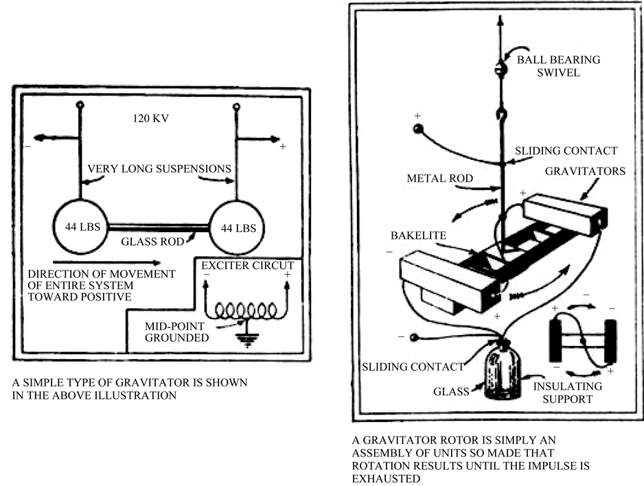
Figure 4. Two drawings from T. Townsend Brown’s famous article “How I Control Gravitation” which includes the polarity of the applied voltage and therefore a confirmation of the electrokinetic force direction.

Figure 5. Woodward’s #6,098,924 patented impulse engine, also called a flux capacitor. The PZT provides nanometer-sized movements that are timed to an AC signal input. A torsion balance has been used with a pair of force transducers in other designs.
but instantaneous analysis needs to be made to compare current direction into the commercial disk capacitors and the electrokinetic force on the dielectric charges. In every electrogravitics or electrokinetics case, it can be argued, the “neighboring charges” to a capacitor plate will necessarily be those in the dielectric material, which are polarized. The bound electron-lattice interaction will drag the lattice material with them, under the influence of the electrokinetic force. If the combination of physical electron acceleration (which also can be regarded as current flow) and the AC signal current flow can be resolved, it may be concluded that an instantaneous electrokinetic force, depending on dI/dt, contributes to the Woodward-Nordtvedt effect.
4) The Campbell and Serrano capacitor modules (Figure 6 and Figure 7), as well as the electrogravitic craft ARV unit (seen at the end of this article), can also be explained with the electrokinetic force, in the same way that the Brown gravitator force was explained in paragraph 2) above. The current flows in one direction through the capacitor-dielectric and the force is produced in the opposite direction. The Norton AFB electrogravitic craft just has bigger plates with radial sections but the current flow still occurs at the center, across the plates. The Serrano PCT patent diagram is also very similar in construction and operation.
5. Electrokinetics Theory Observations
For parallel plate capacitor impulse probes, like Zinsser, Serrano, Campbell, the Norton AFB craft and both of Brown’s models, the electrokinetic field of Equation (4) provides a working model that seems to predict the nature and direction of the force during charging and discharging phases. More detailed information is needed for each example in order to actually calculate the theoretical electrokinetic force and compare it with experiment. We note that Equation (4) also does not suffer the handicap of Equation (1) since no c2 term occurs in the denominator. Therefore, it can be concluded that AC fields operating on parallel plate capacitors should create significantly larger electrogravitic forces than other geometries with the same dI/dt. However, the current I is usually designated as Iosin(ωt) and its derivative is a sinusoid as well. Therefore, a detailed analysis is needed for each specific circuit and signal to determine the outcome.
Equation (4) also suggests a possible enhancement of the force if a permeable (magnetizable) dielectric is used. Then, the value for μ of the material would normally be substituted for μo [23] .
A further observation of both Equation (1) and Equation (4) is that very fast changes in current, such as a current surge or spark discharge has to produce the most dynamic electrokinetic force, since dI/dt will be very large. The declining current surge, or the negatively sloped dI/dt however, should create an opposing force until the current reverses direction. Creative waveshaping seems to be the answer to this obvious dilemma. Fortunately, a few similar inventions use pulse power electric current generators to create propulsion.
The Taylor patent #5,197,279 “Electromagnetic Energy Propulsion Engine” uses huge currents to produce magnetic field repulsion. The Schlicher patent #5,142,861 “Nonlinear Electromagnetic Propulsion System and Method” predicts hundreds of pounds of thrust with tens of kiloamperes input. The Schlicher antenna current


Figure 6. Capacitor module from Campbell’s NASA patent #6,317,310 (left) which creates a thrust force as tested by Naudin. Disk 14 is copper; Struts 16 are dielectrics; Cylinder 15 is a dielectric; Cylinder 12 is an axial capacitor plate; Support post 11 is also dielectric. Compare with the Styrofoam and aluminum foil model (right) built by J. L. Naudin to test the Campbell NASA design, proving it produces thrust.

Figure 7. Capacitor propulsion device with alternating metal and dielectric layers from Serrano’s PCT patent WO 00/58623 with upward thrust direction indicated and + and ? polarity designated on the side.
input is a rectified current surge produced with an SCR-triggered DC power source as in Figure 8 taken from the patent. The resulting waveform has a very steep leading edge but a slowly declining trailing edge, which should also be desirable for the electrokinetic force effect. Furthermore, if this waveform is continued into the negative current direction below the horizontal axis, all of that particular region reinforces the electrokinetic force, with no opposing forces. Therefore, a complete sinusoidal wave, with Schlicher-style steep rise-times is recommended for a signal that contributes to a unidirectional force during 75% of its cycle.
Another observation that should be mentioned is that this electrokinetic force theory does not include the mass contribution as with the electrogravitic force which Saxl, Woodward, and Brown’s 1929 gravitator emphasize. A contributor to the Volume II anthology, Takaaki Musha offers a derived equation for electrogravitics that does include a mass term but not a derivative term [24] . His model is based on the charge displacement or “deformation” of the atom under the influence of a capacitor’s 18 kV high voltage field and his experimental results are encouraging. He also includes a reference to Dr. Ning Li and her gravitoelectric theory [25] . It is noted that Ning Li was the Chair of the 2003 Gravitational Wave Conference sponsored by the Mitre Corporation thinktank in Virginia. The Proceedings of the Gravitational Wave Conference (on CD-ROM), including all of the papers is available from Integrity Research Institute.
A final concern, which may arise from the very nature of the electrokinetics force description, is the difficulty of conceptualizing or simply accepting the possibility of an unbalanced force creation pushing against space. This author has wrestled with this problem in other arenas for years. Three examples include (1) the homopolar generator which creates back torque that ironically, pushes against space to implement the Lorentz force to slow down the current-generating spinning disk [26] . Secondly (2), there is the intriguing spatial angular momentum discovery by Graham and Lahoz [27] . They have shown, reminiscent of Feynman’s “disk paradox”, that the va- cuum is the seat of Newton’s third law much the same as Haisch, Rueda and Puthoff have shown that inertia has its seat in the quantum vacuum [28] . A torsion balance is the Graham and Lahoz chosen apparatus to demonstrate the pure reaction force with induction fields. Their reference to Einstein and Laub’s papers cites the time derivative of the Poynting vector S = E × H integrated over all space to preserve Newton’s third law. Graham

Figure 8. The ideal electrokinetic’s current waveform may possibly be found in Schlicher propulsion patent #5,142,861.
and Lahoz predict that magnetic flywheels with electrets will circulate energy to push against space. Lastly, for (3), the Taylor and Schlicher inventions push against space with an unbalanced force that is electromagnetic in origin.
6. Historical Electrogravitics
In the Historical Section of the Volume II book, gravity articles like the NY Herald-Tribune series and Interavia were some of the last few public pronouncements of the progress of this research. They were published in 1955 and 1956 respectively, at the same time when the British Aviation Studies reports spanning 1954-1956 were published (see Electrogravitics Systems or “Volume I”). The aviation industry interest in this science was at an all-time high, mostly spurred on by Brown’s gravitator experiments. After all, aircraft are very massive and Brown’s theory encourages the use of massive gravitators with high voltage, which we find in the B-2 bomber today.
Dr. Paul LaViolette published a paper which documents how the B-2 advanced propulsion and stealth mode utilizes a high voltage polarity as seen in Figure 10 between the leading edge of the wind and the oppositely charged exhaust from a flame jet generator to create additional electrogravitic forward thrust [29] .
A fascinating article at the end of the 1950s surge in the gravity research is the report from 1961 in Missiles and Rockets, which identifies a 389-page study released by the Office of Technical Services at the US Dept. of Commerce (OTS #61-1187) [30] . The study however, sadly relates that disagreements among experts were becoming unyielding without more experimental proof.
Today, experimental proof seems to be in abundance. However, the prevailing trend by the government still fails to acknowledge the historical pioneering work of Biefeld and Brown, as well as any small inventor who is successful in this area. Take for example, Hector Serrano, who was interviewed in 1998 by NASA scientist Jonathan Campbell on video, about his electropropulsion invention. Within two years, Campbell started filing for a series of patents “on similar technology” and not referencing T. T. Brown nor Serrano in any of his US patents #6,317,310, #6,411,493, or #6,775,123 [31] . This type of behavior by a government representative is unethical and fuels the wide-spread public concern about ulterior government motives. Remarkably, it is like history repeating the same treatment that T. T. Brown received from the military upon demonstrating his working model to them [32] . A good seven-minute video summary of the Biefeld-Brown effect and the advanced technology of the B-2 is online at http://www.youtube.com/watch?v=8WsSXiEDLc8.
7. Eye Witness Testimony of Advanced Electrogravitics
Besides the blue glow of the leading edge of the B-2 in Figure 9, seen by a colleague of the author who happens to be an engineer from the US Department of Energy at night outside his home in Upper Marlboro, MD, a more impressive eye witness account has been given by aeronautics illustrator Mark McCandlish. Mark offers us the conclusive perspective of the covert, flat-bottomed saucer hovercraft seen by dozens of invited eye-witnesses and a Congressman at Norton Air Force Base on November 12, 1988 (a complete description by Mark McCandlish is included in the last chapter of Volume II). When this author spoke to Dr. Hal Puthoff (Institute of Advanced Study, Austin, TX) about Mark’s story, shortly after the famous Disclosure Event at the National Press Club in 2000 [33] , he explained to me that he had already performed due diligence on it and checked on each individual to corroborate the details of the story. Hal emailed me in 2006 that he put this event “in my gray box

Figure 9. The Northrop B-2 bomber which became available in 1994 (when Volume I was published) remains a technological wonder even today since it has flown missions to the mid-east and back without refueling. Eye witnesses have reported the leading edge glows blue at night, apparently because it is using its high voltage electrogravitic propulsion that AFRL has proven also produces laminar air flow.
of possibly true”. Since Dr. Puthoff used to work for the CIA for ten years, this was quite an endorsement, even though it was a cautionary statement from him.
In analyzing the Electrogravitic Craft Demonstration unit (seen by several eye witnesses at Norton AFB in 1988) diagrammed in Figure 11 by Mark McCandlish, this author has compared it to Campbell’s and Serrano’s patented design. A lot can be learned from studying the intricacies of this advanced design, also called an “Advanced Research Vehicle” (ARV) including the use of a distributor cap style of pulse discharge and multiple symmetric, radial plates with dielectrics in between.
Why Americans should pay twice for the development of 21st century energy and propulsion technology is an issue that several US Congressmen have publicly protested. We pay for the “black project budget [34] ” (the difference between the Pentagon’s defense budget and its acknowledged expenses) in billions of tax dollars every year4. We also are asked to pay for DOE, NASA, AF, Navy, DARPA and other agencies to reinvent the same technologies in an unclassified arena.
In 2005, Deputy Director Bennett Hart of the National Reconnaissance Office (NRO) gave a lecture at the National Space Society in Washington DC. In the hall, we discussed my conviction that inertial shielding is already available in classified projects and that it would help all efforts to launch spacecraft. He told me that it seems to be easier to direct contractors to develop technology that he knows already exists, mainly because declassification is very difficult. This is the main reason that we still use World War II technology on land and in space while the environment suffers irreparable harm. My sincere hope is that the validating science contained in Volume II will accelerate the civilian adaptation of this relatively simple propulsion technology.
The scientific articles in the Volume II anthology show the contrasting opinion that still exists in the assessment of electrogravitics. As inertial shielding also is reinvented by civilian scientists, Integrity Research Institute projects that electrogravitics will become more and more useful and a primary means of transportation in outer space. The reason behind this prediction is that any force moving a mass utilizes Newton’s Second Law, F = ma, which can be very powerful when the inertial mass m is reduced by electrogravitic shielding. Once again, such a

Figure 10. Diagram of Dr. Paul LaViolette’s discovery regarding the B-2 auxiliary propulsion system using electrogravitics.
technological development already exists, as exhibited in the night photos of right-angle turns and fast acceleration of covert, black project triangular and circular craft which are operated by classified projects in America that are close to becoming unclassified, according to some experts, since they are now being sighted by civilians.

Figure 11. The impressive Advanced Research Vehicle (ARV) hovercraft diagrammed by aerospace illustrator, Mark McCandlish, which he calls the “Fluxliner”, is powered by pulsed electrokinetics as the distributor cap rotates and fires three equidistant capacitor banks at a time. An online documentary called “Zero Point, the Story of Mark McCandlish and the Fluxliner” contains extensive details about the craft and Mark’s experience with the eye witnesses, which included a Congressman.
8. Conclusion
The most significant conclusion from the multi-faceted research contributing to this article is the observation made by Prof. Jefimenko in his book about the logical theoretical prediction from the electrokinetic equation that an electrokinetic impulse is produced when the “current is switched on”. This implies a very steep leading edge of the current slope resulting in a large electrokinetic force. Whether the mystery of mass will be solved to understand the true nature of electrogravitics, this author finds that pulsed electrokinetics has been proven beyond mere speculation and conjecture. With the advanced technology that is anticipated from the implementation of electrokinetics and possibly electrogravitics, it is hoped and expected that civilian research will eventually catch up to the black project back-engineered propulsion systems that already exist. We should realize that climate change is becoming more and more of a threat, so the hope of utilizing electrokinetics exhaust-free propulsion will be a dream to come true. We can look forward to the day when a so-called antigravity electrogravity craft will be parked in every suburban garage, instead of the old-fashioned, 1930s-style, land-based fossil fuel burner on wheels called “cars” that we are all too familiar with. Then, instead of burning oil and causing tons of pollution to go into the atmosphere, we will be using an onboard electrical system to generate high voltage with very little current, and along with a built-in inertial mass shield which is another subject of research, we will have the freedom of leaving the atmosphere for a jaunt to a space hotel or to the moon for an afternoon drive in outer space.
Acknowledgements
Sincere acknowledgement and gratitude is given to Mark McCandlish for allowing the concluding details of this article to be made public, at great personal risk. Acknowledgement is also given to NRO Deputy Director Bennet Hart for candidly discussing the ongoing backlog issues of declassification, which often last more than fifty years on the average. Acknowledgement is given to the great contribution to this field of knowledge by the late Rudolf Zinsser and T. Townsend Brown, whose untiring work has made electrogravitics and electrokinetics a respectable field for scholarly investigation.
References
- Valone, T. (2008) Electrogravitics Systems Volume I: Reports on a New Propulsion Methodology. 6th Edition, Integrity Research Institute, Beltsville. www.IntegrityResearchInstitute.org
- Valone, T. (2008) Electrogravitics II: Validating Reports on a New Propulsion Methodology. 3rd Edition, Integrity Research Institute, Beltsville.
- Salla, M. (2009) Obama Administration First 100 Days to Promote Antigravity Technology. Honolulu Exopolitics Examiner. http://tinyurl.com/qzbub64
- Zinsser, R.G. (1981) Mechanical Energy from Anisotropic Gravitational Fields. First International Symposium on Non-Conventional Energy Technology (FISONCET), University of Toronto, Ontario, K1R 6G8.
- Valone, T. (2005) The Zinsser Effect: Cumulative Electrogravity Invention of Rudolf G. Zinsser. Integrity Research Institute, Beltsville, IRI #701, 130 p. http://www.goede-stiftung.org/uk/experimente/E_Zinsser_final.pdf
- Cravens, D.L. (1994) Electric Propulsion/Antigravity. Electric Spacecraft Journal, 13, 30.
- Peschka, W. (1998) Kinetobaric Effect as Possible Basis for a New Propulsion Principle. (Raumfahrt-Forschung, Feb, 1974. Translated Version Appears in Infinite Energy, Issue 22, p. 52 and The Zinsser Effect.)
- Valone, T. (1993) Inertial Propulsion: Concept and Experiment, Part 1. Proceedings of the International Energy Conversion Engineering Conference, IRI Report #608. www.IntegrityResearchInstitute.org
- Valone, T. (2014) Bioelectromagnetic Healing: A Rationale for Its Use. 11th Edition, Integrity Research Institute. (Also see “Pulsed Electromagnetic Field Health Effects” IRI Report #418, which explain the beneficial therapy which PEMFs produce on biological cells.)
- Saxl, E. (1967) Device and Method for Measuring Gravitational and Other Forces. US Patent No. 3,357,253.
- Saxl, E.J. (1964) An Electrically Charged Torque Pendulum. Nature, 203, 136-138. http://dx.doi.org/10.1038/203136a0
- Saxl & Allen (1996) Observations with a Massive Electrified Torsion Pendulum: Gravity Measurements during Eclipse. Unpublished Manuscript, IRI Report #702. (Note: 2.2 lb = 1 kg) www.IntegrityResearchInstitute.org
- Woodward, J.F. and Mahood, T.L. (2000) Mach’s Principle, Mass Fluctuations, and Rapid Spacetime Transport. California State University Fullerton, Fullerton.
- Cramer, J.G., Fey, C.W. and Casissi, D.V. (2001) Tests of Mach’s Principle with a Mechanical Oscillator. American Institute of Aeronautics and Astronautics, AIAA-2001-3908.
- Woodward, J.F. (1990) A New Experimental Approach to Mach’s Principle and Relativistic Gravitation. Foundations of Physics Letters, 3, 497-506. http://dx.doi.org/10.1007/BF00665932
- Nordtvedt, K. (1988) Existence of the Gravitomagnetic Interaction. International Journal of Theoretical Physics, 27, 1395-1404. http://dx.doi.org/10.1007/BF00671317
- Mahood, T. (1999) Propellantless Propulsion: Recent Experimental Results Exploiting Transient Mass Modification. Proceedings of Space Technology and Applications International Forum (STAIF-99), 31 January-4 February 1999, Albuquerque, American Institute of Physics.
- Zinsser, R.G. (1981) Mechanical Energy from Anisotropic Gravitational Fields. Proceedings of FISONCET, Toronto, 298.
- Woodward, J. (2004) Flux Capacitors and the Origin of Inertia. Foundations of Physics, 34, 1475-1514. Also see “Tweaking Flux Capacitors”. Proceedings of STAIF, 2005. http://dx.doi.org/10.1023/B:FOOP.0000044102.03268.46
- Jefimenko, O. (2000) Causality, Electromagnetic Induction and Gravitation. Electret Scientific Co., Star City, 29.
- Jefimenko, O. (2000) Causality, Electromagnetic Induction and Gravitation. Electret Scientific Co., Star City, 31.
- Jefimenko, O. (2000) Causality, Electromagnetic Induction and Gravitation. Electret Scientific Co., Star City, 47.
- Einstein, A. and Laub, J. (1908) Annalen der Physik, 26, 533, 541. (Two articles on the subject of a moving capacitor with a “dielectric body of considerable permeability”. Specific equations are derived for magnetic dielectrics predicting the resulting EM fields. Translations of both articles are reprinted in Valone, Thomas, The Homopolar Handbook, Integrity Research Institute, 122-136. Also see Clark’s dielectric-magnetic homopolar generator patent #6,051,905).
- Musha, T. (2008) Possibility of a Strong Coupling Between Electricity and Gravitation. Electrogravitics II: Validating Reports on a New Propulsion Methodology, Integrity Research Institute, Beltsville, 61.
- Torr, D.G. and Li, N. (1993) Gravitoelectric-Electric Coupling via Superconductivity. Foundations of Physics Letters, 6, 371-383. http://dx.doi.org/10.1007/BF00665654
- Valone, T. (2001) The Homopolar Handbook: A Definitive Guide to Faraday Disk and N-Machine Technologies. 3rd Edition, Integrity Research Institute, Beltsville.
- Graham, G.M. and Lahoz, D.G. (1980) Observation of Static Electromagnetic Angular Momentum in Vacuo. Nature, 285, 154-155.
- Haisch, B., Rueda, A. and Puthoff, H.E. (1994) Inertia as a Zero-Point-Field Lorentz Force. Physical Review A, 49, 678. http://dx.doi.org/10.1103/PhysRevA.49.678
- Laviolette, P.A. (2008) The U.S. Antigravity Squadron. Secrets of Antigravity Propulsion, Bear & Co., Rochester, 142.
- Beller, W. (1961) Soviet Efforts Are Closely Watched. Missiles and Rockets, 11 September 1961, 27.
- Young, K. (2002) Inventor: NASA Stole Patent Idea. Florida Today, 29 September 2002.
- The Townsend Brown Electro-Gravity Device, File 24-185, Subject: Special Inquiry―A Comprehensive Evaluation by the Office of Naval Research with Accompanying Documents. 15 September 1952, Reprinted by Integrity Research Institute.org―IRI Report #612.
- Greer, S. (2001) Disclosure: Military and Government Witnesses Reveal the Greatest Secrets in Modern History. Crossing Point, Afton.
- Andrews, W. and Lindeman, T. (2013) The Black Budget―Funding the Intelligence Program. Washington Post, 29 August 2013.
Nomenclature
J = electric current density
I = electric current
Ek = electrokinetic force vector
B = magnetic flux density
E = electric field
ρ = charge density
S = Poynting vector
NOTES

1Volume II, “Testimony of Mark McCandlish” (pp. 131-145) shows that the Air Force took note in that the electrogravitic demonstration ARV shown at Norton AFB in 1988 had a rotating distributor for electrically pulsing sections of multiply-layered dielectric and metal plate pie-shaped sections with high voltage discharges for an electrokinetic force.
2Compare Figure 1 graph to Brown’s ONR graph on p. 136 of Volume I (6th ed.).

3Brown’s second patent #2,949,550 (see Appendix of Volume I: two electrokinetic saucers on a maypole) has movement toward the positive charge, so the same electrokinetic theory explained above works for both.

4“The Billion Dollar Secret” narrated by defense journalist Nick Cook, aired on TLC (The Learning Channel) in 2000 about the black projects and the money spent on them.