Open Journal of Fluid Dynamics
Vol.07 No.04(2017), Article ID:81358,15 pages
10.4236/ojfd.2017.74042
Mixed Convective Flow of Micropolar Fluids past an Inclined Porous Flat Plate
Nadim Sheikh1, Maruf Hasan2
1Department of Mathematics, University of Dhaka, Dhaka, Bangladesh
2Department of Mathematics, Comilla University, Comilla, Bangladesh
![]()
Copyright © 2017 by authors and Scientific Research Publishing Inc.
This work is licensed under the Creative Commons Attribution International License (CC BY 4.0).
http://creativecommons.org/licenses/by/4.0/


Received: November 9, 2017; Accepted: December 25, 2017; Published: December 28, 2017
ABSTRACT
Mixed convective flow of a viscous incompressible electrically conducting micropolar fluid along a semi-infinite inclined permeable flat plate with viscous dissipation has been analyzed numerically. With appropriate transformations the boundary layer equations are transformed into a set of nonlinear ordinary differential equations. The local similarity solutions of the transformed dimensionless equations for the flow, microrotation and the heat transfer characteristics are evaluated using Nachtsheim-Swigert shooting iteration technique (guessing the missing value) together with sixth order Runge-Kutta-Butcher integration scheme. Numerical results are presented in the form of non-dimensional velocity, microrotation and temperature profiles within the boundary layer for different parameters entering into the analysis. The effects of pertinent parameters on the local skin friction coefficient (viscous drag), plate couple stress and rate of heat transfer (Nusselt number) are also displayed graphically.
Keywords:
Micropolar Fluid, Viscous Dissipation, Heat Generation, Stream Function

1. Introduction
Micropolar fluids are those which contain micro-constituents that can undergo rotation, the presence of which can affect the hydrodynamics of the flow so that it can be distinctly non Newtonian. These fluids are fluids with microstructure belonging to a class of complex fluids with nonsymmetrical stress tensor referred to as micromorphic fluids. It has many practical applications, for examples analyzing the behavior of exotic lubricants, the flow of colloidal suspensions or polymeric fluids, liquid crystals, additive suspensions, animal blood, body fluids, and turbulent shear flows.
Convective flows over a flat plate that is immersed in a micropolar fluid has attracted an increasing amount of attention since the early studies of Eringen [1] deals with a class of fluid which exhibits certain microscopic effect arising from the local structure and micromotions of the fluid elements. These fluids contain dilute suspensions with rigid micromolecules with individual motions, which supports stress and body moments and are influenced by spin inertia. Many investigators have studied and reported results for micropolar fluids of whom the names of Jena and Mathur [2] , Gorla and Takhar [3] , Yucel [4] , Gorla [5] are worth mentioning. Char and Chang [6] have studied the laminar free convective flow of the same fluid past an arbitrary curved surface. Rees and Pop [7] investigated the free convection boundary layer flow in the same flow condition. Desseauax and Kelson [8] studied the flow of micropolar fluid bounded by stretching sheet. Perdikis and Raptis [9] studied the heat transfer of micropolar fluid in the presence of radiation. Raptis [10] studied the same fluid flow past a continuously moving plate in the presence of radiation. Rahman and Sattar [11] described transient convective flow of micropolar fluid past a continuously moving vertical porous plate in the presence of radiation. Alam et al. [12] analyzed MHD free convective heat and mass transfer flow past an inclined surface with heat generation.
The study of magnetohydrodynamic (MHD) flow of an electrically conducting fluid is of considerable interest in modern metallurgical and metal-working processes. There has been a great interest in the study of Magnetohydrodynamic flow and heat transfer in any medium due to the effect of magnetic field on the boundary layer flow control and on the performance of many systems using electrically conducting fluids. This type of flow has attracted the interest of many researchers due to its applications in many engineering problems such as MHD generators, plasma studies, nuclear reactors, geothermal energy extractions. By the application of magnetic field, hydromagnetic techniques are used for the purification of molten metals from non-metallic inclusions. So such type of problem that we are dealing with is very much useful to polymer technology and metallurgy. Rahman and Sattar [13] studied magnetohydrodynamic convective flow of a micropolar fluid past a continuously moving vertical porous plate in the presence of heat generation/absorption.
The aim of the present work is to study the mixed convective flow of micropolar fluids past an inclined porous plate with viscous dissipation effect. The resulting governing equations are solved by Nachtsheim-Sweigert shooting iteration technique together with Runge-Kutta-Butcher initial value solver and reported graphically.
2. Governing Equations of the Flow
A two-dimensional steady MHD laminar mixed convective flow of a viscous incompressible electrically conducting micropolar fluid along a semi-infinite inclined permeable flat plate with an acute angle α to the vertical is considered. With x-axis measured along the plate, a magnetic field of uniform strength B0 is applied in the y-direction which is normal to the flow direction. Fluid injection or suction is imposed at the plate surface. The external flow takes place in the direction parallel to the inclined plate and has the uniform velocity . The temperature of the surface is held uniform at Tw which is higher than the ambient temperature . The flow configuration and coordinate system are shown in the following Figure 1.
We further assume that: 1) the fluid has constant kinematic viscosity and thermal diffusivity, and that the Boussinesq approximation may be adopted for steady laminar flow, 2) the magnetic Reynolds number is taken to be small enough so that induced magnetic field is assumed to be negligible in comparison with applied magnetic field so that , where b0 is the uniform magnetic field acting normal to the plate, 3) Joule heating is negligible. Within framework of such assumptions, the governing equations for this problem can be written as follows:
Continuity Equation:
(1)
Momentum Equation:
(2)
Angular Momentum Equation:
(3)
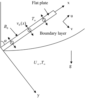
Figure 1. Flow configurations and coordinate system.
Energy Equation:
(4)
where u, v are the velocity components along x, y co-ordinates respectively, v is the kinematic viscosity is the apparent kinematic viscosity, μ is the
coefficient of dynamic viscosity, S is the microrotation coupling coefficient (also known as the coefficient of gyro-viscosity or as the vortex viscosity), ρ is the mass density of the fluid, σ is the microrotation component normal to the
xy-plane, b0 is the uniform magnetic field acting normal to the plate,
is the microrotation viscosity or spin-gradient viscosity, is the magnetic permeability, j is the micro-inertia density, T is the temperature of the fluid within the boundary layer, is the temperature of the fluid outside the boundary layer, is the velocity of the fluid far away from the plate, is the specific heat of the fluid at constant pressure, k is the thermal conductivity, g0 is the acceleration due to gravity, is the volumetric coefficient of thermal expansion.
2.1. Boundary Conditions
The appropriate boundary conditions of the model are:
(5)
where the subscripts w and refer to the wall and boundary layer edge, respectively. The value corresponds to an impermeable plate. When microrotation parameter we obtain which represents no-spin condition i.e. the microelements in a concentrated particle flow-close to the wall are not able to rotate as stated by Jena and Mathur [2] . The case repre- sents vanishing of the anti-symmetric part of the stress tensor and represents weak concentration. For this case Ahmadi [14] suggested that in a fine particle suspension the particle spin is equal to the fluid velocity at the wall. The case corresponding to be representative of turbulent boundary layer flows.
2.2. Similarity Analysis
In order to obtain similarity solution of the problem we introduce the following non-dimensional variables:
(6)
where is the stream function, is the dimensionless distance normal to the sheet, f is the dimensionless stream function, is the dimensionless fluid temperature
Since and we have the velocity components
(7)
where prime denotes the derivative with respect to .
Now substituting Equations (6) and (7) into Equations (2)-(4) we obtain
(8)
(9)
(10)
In the above equations we have used the following non-dimensional parameters:
is the coupling parameter,
is the Richardson parameter,
is the local Grashof number,
is the local Reynolds number,
is the vortex viscosity parameter,
is the spin gradient viscosity parameter,
is the local magnetic field parameter,
is the Prandtl number.
The corresponding boundary conditions become
(11)
where is the suction/injection velocity at the plate for and .
The parameters and correspond to local effects i.e. pertaining to specific values of . Therefore (8)-(10) are ordinary differential equations that are locally similar together with the boundary conditions (11). The above-noted systems have been solved numerically for various values of the parameters entering into the problem.
3. Method of Numerical Solution
The set of nonlinear ordinary differential Equations (8)-(10) with boundary conditions (11) are non-linear and coupled. It is difficult to solve them analytically. Hence we adopt a procedure to obtain the solution numerically. Here we use the standard initial-value solver shooting method namely Nachtsheim-Swigert (1965) shooting iteration technique (guessing the missing value) together with sixth order Runge-Kutta-Butcher initial value solver.
Important Physical Parameters
The quantities of chief physical interest are the skin friction coefficient (viscous drag), plate couple stress and the Nusselt number i.e., rate of heat transfer.
Skin friction coefficient:
The equation defining the wall shear stress is
(12)
The local skin friction coefficient is defined as
(13)
Thus from Equation (13) we see that the local values of the skin friction coefficient is proportional to .
Plate couple stress:
The equation defying the plate couple stress is
(14)
The dimensionless couple stress is defined by
(15)
Thus the local plate couple stress in the boundary layer is proportional to .
Nusselt number:
The local heat flux may be written by Fourier’s law as
(17)
The local heat transfer coefficient is given by
(17)
The local Nusselt number may be written as
(18)
Thus from Equation (18) we see that the local Nusselt number is proportional to .
4. Results and Discussion
The velocity, temperature and microrotation profiles of convective flow of a viscous incompressible electrically conducting micropolar fluid past an inclined porous flat plate considering viscous dissipation effect has been investigated numerically by using Nachtsheim-Swigert shooting iteration technique. The values of the parameters are taken to be fixed as 1, 0.2, 0.2 and 2.0 respectively, whereas the effects of the other important parameters, namely magnetic field parameter , Prandtl number , Eckert number , suction parameter over these profiles have been studied. The value of the Richardson parameter (buoyancy parameter) corresponds to mixed convection.
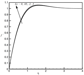
Figures 2(a)-(c), respectively, show the velocity, temperature and microrotation profiles for different values of Eckert number. From Figure 2(a) it can be seen that velocity profile increases slowly with the increases of Ec. From Figure 2(b) we see that temperature profile increases with the increase of Eckert number. From Figure 2(c) we observe that values of Ec introduce negligible decreasing effect on the microrotation profiles.
Figures 3(a)-(c), respectively, illustrate the velocity, temperature and microrotation profiles for different values of suction parameter . From Figure 3(a) it can be seen that velocity profile increases hence momentum boundary layer thickness decreases with the increase of suction parameter indicating the usual fact that suction stabilizes the boundary layer growth. From Figure 3(b) we see that temperature profile decreases monotonically with the increase of suction parameter . It is also observer that thickness of the thermal boundary layer decreases with the increase of the suction parameter. From Figure 3(c) we study that suction parameter has increasing effect on the microrotation profiles except very close to the surface of the plate where these profiles increase with the increase of .
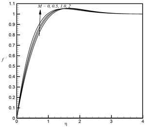
Figures 4(a)-(c), respectively, describe the velocity, temperature and microrotation profiles for different values of magnetic field parameter M. From Figure 4(a) it can be observed that close to the surface of the plate fluid velocity increases with the increase of magnetic field parameter M whereas far away from it fluid velocity decreases with the increase of M. This is not surprising realizing the fact that fluid elements near the wall are accelerated by the Lorentz force induced by the magnetic field. But away from the plate Lorentz force tends to retard the motion of the fluid. From Figure 4(b) we see that temperature profile decreases slowly with the increase of magnetic field parameter M. From this figure it also clear that thermal boundary layer thickness decreases with the increase of the magnetic field parameter. From Figure 4(c) we see that microrotation profile increases i.e., microrotational boundary layer thickness decreases with the increase of magnetic field parameter M.
 (a)
(a)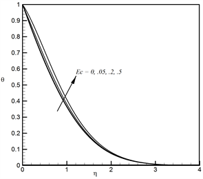 (b)
(b)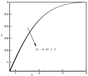 (c)
(c)
Figure 2. (a) Effect of Ec on velocity profiles; (b) Effect of Ec on temperature profiles; (c) m Effect of Ec on microrotation profiles.
 (a)
(a)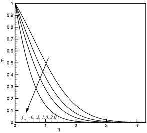 (b)
(b) (c)
(c)
Figure 3. (a) Effect of fw on velocity profiles; (b) Effect of fw on temperature profiles; (c) Effect of fw on microrotation profiles.
 (a)
(a)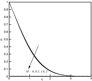 (b)
(b) (c)
(c)
Figure 4. (a) Effect of M on velocity profiles; (b) Effect of M on temperature profiles; (c) Effect of M on microrotation profiles.
Figures 5(a)-(c), respectively, are drawn to show the velocity, temperature and microrotation profiles for different values of Prandtl number Pr. From Figure 5(a) it is clear that velocity profile decreases with the increase of Prandtl number Pr. Figure 5(b) shows temperature profile decreases with the increase of Prandtl number Pr. From Figure 5(c) we see that microrotation increases with the increase of Prandtl number Pr. Therefore Prandtl number decreases the velocity as well as thermal boundary layer thickness.
 (a)
(a)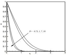 (b)
(b) (c)
(c)
Figure 5. (a) Effect of Pr on velocity profiles; (b) Effect of Pr on temperature profiles; (c) Effect of Pr on microrotation profiles.
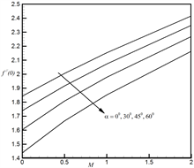
In Figures 6(a)-(c), respectively, we have presented the physical parameters and which are respectively proportional to skin friction coefficient, plate couple stress and Nusselt number for different values of angle of inclination α and magnetic field parameter M. From Figure 6(a) and Figure 6(b) we see that skin friction (Cf) and plate couple stress ( ) decreases with the increase of α and increases with the increase of M. Figure 6(c) shows that Nusselt number ( ) increases with the increase of α and decreases with the increase of M. Thus changing angle of inclination we can control the hydrodynamic, microrotational and thermal boundary layer characteristics.
 (a)
(a)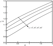 (b)
(b)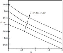 (c)
(c)
Figure 6. (a) Variation of for α and M; (b) Variation of or α and M; (c): Variation of for α and M.
Figures 7(a)-(c), respectively, show that skin friction coefficient, plate couple stress and Nusselt number for different values of Eckert number Ec and suction parameter . From Figure 7(a) and Figure 7(b) we see that skin friction ( ), plate couple stress ( ) increases slowly with the increase of and increases rapidly with the increase of Figure 7(c) shows that Nusselt number ( ) decreases with the increase of Ec while it increases with the increase of .
![]() (a)
(a)![]() (b)
(b)![]() (c)
(c)
Figure 7. (a) Variation of for Ec and fw; (b) Variation of for Ec and fw; (c) Variation of for Ec and fw.
5. Conclusions
A numerical study has been performed to investigate the effect of various parameters such as suction parameter , Prandtl number Pr, Eckert number Ec, magnetic field parameter M on the velocity, temperature and microrotation profiles and discussed them from the physical point of view.
Skin friction coefficient increases with the increase of magnetic field parameter M, suction parameter , Eckert number Ec. This coefficient decreases with the increase of angle of inclination α and Prandtl number Pr.
Nusselt number increases with the increase of suction parameter , angle of inclination α, and Prandtl number Pr. Nusselt number decreases with the increase of magnetic field parameter M, Eckert number Ec.
Plate couple stress increases with the increase of magnetic field parameter M, suction parameter , Eckert number Ec. This coefficient decreases with the increase of angle of inclination α and Prandtl number Pr.
Cite this paper
Sheikh, N. and Hasan, M. (2017) Mixed Convective Flow of Micropolar Fluids past an Inclined Porous Flat Plate. Open Journal of Fluid Dynamics, 7, 642-656. https://doi.org/10.4236/ojfd.2017.74042
References
- 1. Eringen, A.C. (1966) Theory of Micropolar Fluids. Journal of Mathematics Mechanics, 16, 1-18. https://doi.org/10.1512/iumj.1967.16.16001
- 2. Jena, S.K. and Mathur, M.N. (1981) Similarity Solution for Laminar Free Convection Flow of Thermo-Micropolar Fluid past a Non-Isothermal Vertical Flat Plate. International Journal of Engineering Science, 19, 1431-1439. https://doi.org/10.1016/0020-7225(81)90040-9
- 3. Gorla, R.S.R. and Takhar, H.S. (1987) Free Convection Boundary Layer Flow of a Micropolar Fluid past Slender Bodies. International Journal of Engineering Science, 25, 949-962. https://doi.org/10.1016/0020-7225(87)90090-5
- 4. Yucel, A. (1989) Mixed Convection Micropolar Fluid Flow over Horizontal Plate with Surface Mass Transfer. International Journal of Engineering Science, 27, 1593-1608. https://doi.org/10.1016/0020-7225(89)90153-5
- 5. Gorla, R.S.R. (1992) Mixed Convection in a Micropolar Fluid from a Vertical Surface with Uniform Heat Flux. International Journal of Engineering Science, 30, 349-358. https://doi.org/10.1016/0020-7225(92)90080-Z
- 6. Char, M.I. and Chang, C.L. (1995) Laminar Free Convection Flow of Micropolar Fluids from a Curved Surface. Journal of Physics D: Applied Physics, 28, 1324-1331. https://doi.org/10.1088/0022-3727/28/7/008
- 7. Rees, D.A.S. and Pop, I. (1998) Free Convection Boundary Layer Flow of Micropolar Fluid from a Vertical Flat Plat. IMA Journal of Applied Mathematics, 61, 179-197. https://doi.org/10.1093/imamat/61.2.179
- 8. Desseaux, A. and Kelson, N.A. (2000) Flow of a Micropolar Fluid Bounded by a Stretching Sheet. Australia and New Zealand Industrial and Applied Mathematics, 42(E), 536-560.
- 9. Perdikis, C. and Raptis, A. (1996) Heat Transfer of a Micropolar Fluid by the Presence of Radiation. Heat and Mass Transfer, 31, 381-385. https://doi.org/10.1007/BF02172582
- 10. Raptis, A. (1998) Flow of a Micropolar Fluid past a Continuously Moving Plate by the Presence of Radiation. International Journal of Heat and Mass Transfer, 41, 865-866. https://doi.org/10.1016/S0017-9310(98)00006-4
- 11. Rahman, M.M. and Sattar, M.A. (2007) Transient Convective Flow of Micropolar Fluid past a Continuously Moving Vertical Porous Plate in the Presence of Radiation. International Journal of Mathematics and Mathematical Sciences, 12, 497-513.
- 12. Alam, M.S., Rahman, M.M. and Sattar, M.A. (2006) MHD Free Convective Heat and Mass Transfer Flow past an Inclined Surface with Heat Generation. Thammasat International Journal of Science and Technology, 11, 1-8.
- 13. Rahman, M.M. and Sattar, M.A. (2006) Magnetohydrodynamic Convective Flow of a Micropolar Fluid past a Continuously Moving Vertical Porous Plate in the Presence of Heat Generation/Absorption. ASME Journal of Heat Transfer, 128, 142-152. https://doi.org/10.1115/1.2136918
- 14. Ahmadi, G. (1976) Self-Similar Solution of Incompressible Micropolar Boundary Layer Flow over a Semi-Infinite Plate. International Journal of Engineering Science, 14, 639-646. https://doi.org/10.1016/0020-7225(76)90006-9