Open Journal of Civil Engineering
Vol. 3 No. 3 (2013) , Article ID: 36398 , 16 pages DOI:10.4236/ojce.2013.33025
A Fiber Pull-Out Based Model for Synthetic Fiber Reinforced Concrete Beams under a Flexural Load
CE Department, Clarkson University, Potsdam, USA
Email: pagliaa@clarkson.edu
Copyright © 2013 Alessandro Paglia. This is an open access article distributed under the Creative Commons Attribution License, which permits unrestricted use, distribution, and reproduction in any medium, provided the original work is properly cited.
Received June 18, 2013; revised July 18, 2013; accepted July 25, 2013
Keywords: Fiber Reinforced Concrete; Concrete Sample Test; Synthetic Fiber Composite Materials
ABSTRACT
This work is intended to be a simple contribution to building a model able to implement theoretical results related to the random oriented fiber reinforced concrete in a procedure that could be used in structures analysis and design involving fiber reinforced elements. Here follows a short outline: In the introduction chapter the problem is presented together the work done. Section 2 develops some ancillary concepts of this material and its mechanical properties, while in Section 3, following the path of other researchers, the assumptions made to solve the problem are presented, together with the most relevant results related to presence of 3D randomly oriented fiber. In the following section a review of the mechanical process of fiber pull-out is done, and the results, mostly due to Victor Li researches, of a 3D randomly oriented synthetic fiber stress vs crack opening in a pull-out process from a cement matrix. In Section 5 the author, after making some assumptions about the configuration of the strain and crack geometry in the cross section where failure is assume to occur under flexural bending moment, the resultant stress is integrated to find the resultant internal moment vs increasing strain and crack width. In this analysis, the crack bridging law for synthetic fiber in FRC presented in the previous section is taken into account. In Section 6, a procedure to find a cross section configuration in equilibrium under external bending moment has been built. Under the assumption of a perfectly plastic collapse mechanism a numerical simulation is conducted on a specimen that undergoes a four-point bending test. A comparison with the trend of a similar test on a synthetic FRC sample has been done. The work is completed by the conclusions that could be inferred from this work.
1. Introduction
This work deals with composite materials formed by cementitious matrix and inclusion of synthetic fibers, referring in particular to fiber mechanical parameters typical of polyethylene and polypropylene fibers. The goal of this work consists in finding a model, simple but efficient enough to describe the contribution of the inclusion of straight fibers, randomly distributed, to the toughness and ductility of the composite, after briefly illustrating the mechanics of FRC and in particular the fiber pull-out phenomenon, which is assumed, as we see later, to be the most important factor in determining the increased ductility of the material.
An analysis of a post-first crack behavior beam is conducted assuming a rigid-plastic model for a four-point bending test load picture. The assumptions on the strain diagrams and the crack opening profile, even though not directly based on fracture mechanics theory, allow us to define relations between an external moment after the first crack and related displacements. An iterative procedure has been set up to evaluate numerically beam configurations under bending moment and a subroutine has been programmed to implement this procedure
2. Fiber Reinforced Concrete
Mechanical Behavior of FRC Concrete: Ancillary Concepts
A composite material can be defined as a material formed by two or more elements mixed on a macroscale [1]. This new material has particular properties that none of its components, used alone, can provide. We know that cementitious materials generally have poor tensile strength and low fractural toughness. Fibers are inclusions for which one dimension, the length, is dominant over the other two. They can be aligned in one direction or randomly oriented in a plane or in space, and they can be made of different materials (i.e. steel glass, asbestos, carbon, nylon, polypropylene, Kevlar and others).
One of the most important limits to the fiber percentage is given by the workability and the bundle phenomenon. The first is well known in the concrete technology, and it regards the difficulty of pumping the mixture and casting it correctly into the molds due to an incorrect mix design or a too low water/cement ratio. The second limit is due to the trend of a group of fibers to be tightly bounded together, so that the total surface of the bundle in touch with the matrix is lower than the sum of fibers taken individually. To avoid this, it is necessary to reduce the percentage of fiber and to take care of the mixing phase technique. Currently, one of the materials most commonly used in FRC is steel fibers, which can be straight or hooked [1]. The other most common solution is given by synthetic fibers such as Polyethylene, Polypropylene, Nylon and Kevlar. Compared to steel fibers, synthetic fibers generally cannot provide neither the same stiffness increment nor the same peak value when tensile deformation of the composite reaches the ultimate strain of the matrix. However, [2] they present the advantages of a greater ductility and higher resistance to aggressive agents. Most importantly, unlike steel fibers, there are kinds of synthetic fibers, in which the interfacial shear stress during the fiber debonding shows a hardening behavior with slippage, due to surface abrasion (Victor Li et al., [3]). The main contribution of fibers to composite cementitious material consists in converting a brittle material to pseudo-ductile material. That is, independently of the behavior of composite after its first crack (hardening of softening), the ultimate FRC strain is generally much greater with respect to the plain matrix; In general, although the failure mechanisms are more complicated, we can divide the failure mechanisms related to cementitious matrix composites into the following modes:
1) fiber pull-out (the composite failure occurs when the fibers are completely debonded).
2) fiber failure (fiber fracture).
According Kelly and Lilholt (1973) (cfr [1]) the composite tensile strength for the two specific modes can be predicted as follows:
Fiber pull-out:
 (1)
(1)
Fiber failure:
 (2)
(2)
where the coefficient Φi assumes values around 1/6. Vf is fibers volume/matrix volume ratio σm and σf are the failure stress for matrix and fibers respectively Em, Ef are the Young moduli for matrix and fibers respectively.
In cement based composites the fiber failure strain is usually much greater than that of the matrix
 .
.
That means fibers carry an additional load after matrix failure. The minimum amount of fiber, related to the unit volume that ensures fibers can entirely withstand this additional load after matrix failure occurs is defined as the Critical Fiber Volume Fraction.
This value has been derived by Hannant, D. J. (1978) [4] as
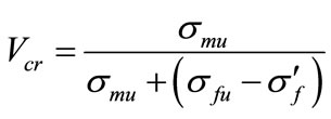 (3)
(3)
where σfu and σmu are the ultimate stress of fiber and matrix respectively, and  is the fiber stress at matrix failure. The critical fiber volume has been estimated at around 0.31% for steel fibers and 0.75% for polypropylene fiber.
3. Principal Assumptions for the Model in the Pre-Cracking Analysis
Before you begin to format your paper, first write and save the content as a separate text file. Keep your text and graphic files separate until after the text has been formatted and styled. Do not use hard tabs, and limit use of hard returns to only one return at the end of a paragraph. Do not add any kind of pagination anywhere in the paper. Do not number text heads—the template will do that for you.
Finally, complete content and organizational editing before formatting. Please take note of the following items when proofreading spelling and grammar:
3.1. Model Behavior in the Pre-Cracking Phase
The principal assumptions made related to this phase are the following:
1) the mod opening depends only on the tensile principal stress (the biggest if both principal stresses are tensile) and the crack direction is orthogonal to this stress.
2) there are no fiber bundles to consider, as the fiber volume Vs cement volume ratio is below 3%, so the fibers are expected to work independently of one another.
3) the fibers are randomly oriented with respect to the crack direction, with somewhat a uniform 3D distribution.
4) the strength of every fiber is high enough to avoid the fiber failure.
5) the behavior of both concrete and fibers remains linear elastic.
6) the axial stiffness is the only relevant stiffness in synthetic fibers.
7) in the pre-cracking phase there is no slippage between the fibers and the matrix, so the fiber strain is equal to the matrix strain till the matrix tensile strain reaches the ultimate strain, that is

These assumptions are somewhat similar to the one on which the reinforced concrete theory is based. We assume the fibers contribute to the composite strength just as the steel rebar contributes to the reinforced concrete strength. The main difference is due to random orientation, and in this work we assume the fibers were cast randomly and are distributed uniformly in space (3D) inside the matrix.
3.2. Stress vs Deformation before the First Cracking, with Fibers Randomly Oriented in 3D
The approach to the 3D model necessary leads to a probabilistic approach [4,5]. We consider a rectangular specimen as shown in Figure 1:
The position of a fiber and the incident angle formed with the normal to a generic cross section can be determined by the following parameters (see Figure 2) : the distance between the fiber centroid from this cross section, and
  the angle in the space formed by the fiber axis with the x direction, corresponding to the stress
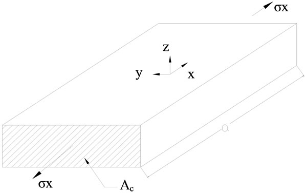
Figure 1. Specimen geometry.
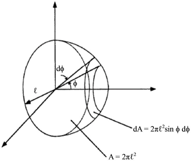
Figure 2. 3D randomly oriented fiber with embedded length l and its end over the hemispherical surface, [4].
direction. We need to obtain the probability function for a fiber to have its position determined by  and
and  with respect to any cross section normal to x direction (see Figure 2).
If we define E1 as the probability that the centroid is inside a range  and E2 as the probability that the fiber has an incident angle between
  and
and , the probability density is given by P[E1]*P[E2], according Bayes’s theory for independent events. (or above version).
However, the only values of  are those that intercept the cross section plane, i.e.
 .
.
We assume the fiber centroid is uniformly distributed so that P[E1] =1/a, but if we refer only to a semi-domain  as in Figure 3, we will obtain the same result multiplying the probability by 2, i.e. P[E1'] =2/a. The probability function P[E2] for uniformly spherical is equal to:
 (4)
(4)
that means the number of fibers dN crossing the cross section plane with  and
and
 is given by
 (5)
(5)
and dN = 0 elsewhere, while where  is the total number of fibers in the specimen, equal to:
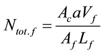 (6)
(6)
The contribution of any fibers to the stress in x direction is equal to
 (7)
(7)
where , the fiber strain is equal to
 (8)
(8)

Figure 3. A fiber crossing a matrix crack and its centroid position.
so the axial resultant due to the fiber elastic deformation
 (9)
(9)
Leads to:
 (10)
(10)
The total tensile force due a strain  is equal to the total tensile force due a strain is equal to
 (11)
(11)
It is possible to define an equivalent Young modulus equal to:

In many cases, synthetic fibers generally have a Young’s modulus not much higher than mortar and concrete’s modulus in the elastic phase under traction, and the percentage used in FRC composites is below 3%, thus we can assume reasonably for our goals:
 (12)
(12)
4. Pull-Out Theory and Modeling for Synthetic FRC
4.1. Single Fiber Pull-Out Theory
The analysis of the single fiber embedded in a matrix is not simple as it depends in general on many parameters; thus, it is necessary to make some assumptions to obtain an analytical solution that can be used with a reasonable number of parameters and produces results generally in agreement with experimental tests. This section has been developed in according with the articles written by other researcher, in particular [5-7] We confirm the assumption from 1) to 6) but they are not enough to work in this scenario, and 7) no longer remains valid for every point of the fiber anymore. Four further important assumptions are necessary:
7’) The fiber that remains in an elastic field (this can’t be always true) is frictionally bonded to the matrix; that is, interfacial stress depends only on the elastic stress at the tip of the debonded zone and on the fiber-matrix relative slippage.
8) The effect of elastic interfacial stress is negligible in the bonded area as it is assumed to decay quickly.
9) After the debonding has occurred for the whole embedded length, the further fiber axial deformation is not considered, so the fiber moves a rigid motion.
10) The effect of the angle ψ formed between the fiber axis and the normal to the crack plane can be taken into account considering the fiber as a frictional rope slipping on a pulley. As a result,
 (4)
(4)
for a single fiber.
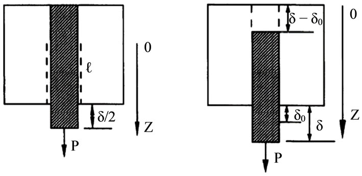
11) Before the crack opens, the matrix strain is assumed to be the same as the fiber strain, and no slippage occurs. After a crack opens, the fiber undergoes a jump in tensile stress as the capacity of the cracked matrix to carry loads vanishes or rapidly decreases with the crack mod. The pull-out of the single fiber and the analysis of fiber matrix interaction after the first crack appears, can be divided in two phases, as shown in Figure 4 consistenly with the assumptions made in 7’), 8) and 9);
a) Fiber debonding: the breakage of the initial cohesion (mechanical or chemical) existing between the fiber and the matrix. It begins where the elastic interfacial stress is supposed to be the highest, in a homogeneous matrix at the crack tip, and it ends with the complete breakage of the cohesion all along the fiber length, i.e. the debonded length is equal to the embedded length.
b) Fiber pull-out: which occurs after the complete debonding.
The fiber experiences a complete slippage with respect to the matrix. Generally, there still exists an interfacial shear stress that depends on the physical characteristics of the fiber surface and varies with the fiber slippage. This phase ends when the fiber is completely pulled out from the matrix.
An important condition to ensure consistency with assumption 4) must be established: the embedded fiber length l must be shorter than the critical length, Lc, defined as the embedded length at which fiber failure can occur.
 (14)
(14)
4.2. Interfacial Shear Stress vs Slippage Law
According to [5] the hardening behavior is relevant for synthetic fibers: in this work, the linear hardening model proposed by Bao and Song [8] has been used, thus the
 (a) (b)
Figure 4. Fiber debonding and fiber pull-out [3]. (a) Fiber deboning; (b) Fiber pull-out.
relation between the shear interface stress and the fiber slippage is the following:
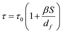 (15)
(15)
where S is slippage, df is fiber diameter, Young’s modulus not much higher than mortar and concrete’s modulus in the elastic phase The values of τ0 and β must be determined from experimental tests.
Phase a)  (debonding) where l is the debonded length and L is the embedded length. We obtain, after setting
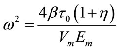 the governing equation in the form [5]:
 (16)
(16)
and, applying the boundary conditions
1) 
2)  for z = 0 it is possible to obtain the solution [2].
 (17)
(17)
thus the load at the free end of the fiber is equal to
 (18)
(18)
and at the end of Phase 1) l = L
 (19)
(19)
As this phase is bilateral and symmetric, we can set the crack opening .
.
 (20)
(20)
and the load is equal to:
 . (21)
Phase 2) (the fiber has been completely debonded).
In this phase, ignoring the further axial deformation according to 9) the slippage is equal to:
 (22)
(22)
and the load to:
 .(23)
.(23)
This value of P (L, δ) is valid only for one side pullout behavior (see Figure 4). However, it has been demonstrated [3] that fibers that can undergo a double side for most actual situations must have the shorter embedded length close to L/2 (see Figure 5 for details) so their relative percentage is low and they can be disregarded. If we had had a constant interfacial shear stress (i.e. ) we would have obtained the following results for δ0 < δ < L (linear decreasing).
 (24)
(24)
4.3. 3D Uniformly Distributed Fibers Pull-Out Theory
The theory developed so far must be extended to a great number of fibers whose position is random to achieve useful results in terms of stress and crack opening. We maintain the assumptions stated before. Thus it is necessary to evaluate the probability that, depending on a given crack opening a fiber can be 1) still embedded in both sides but in a debonding phase;
2) completely debonded and in the phase of slipping in the shorter side and in the debonding phase in the longer side but still intersecting both crack faces.
3) completely pull-out from the shorter embedded side and then removed from the model as providing no contribution to the tensile strength. Thus the bridging stress is according to 9) the slippage is equal to:
 (25)
(25)
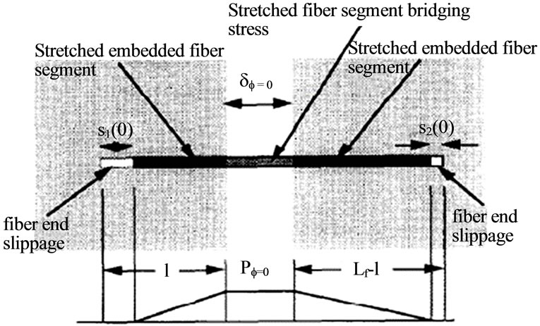
Figure 5. Bilateral pull-out [2].
that gives the following results [6] expressed in non-dimensional terms for  and the load to: (please see Equation (26) below)
and for 
 (27)
(27)
While, for 
 (28)
(28)
 ,
,  ,
,  ,
,
 is the normalized crack opening at which all fibers have completed debonding, and
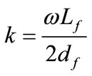
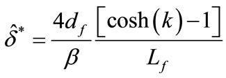
 is the normalizing stress and g is the snubbing factor related to snubbing coefficient f with the relation for uniform fiber distribution in 3D. [1] the influence of slip-hardening parameter β in the debonding stage
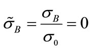
  is practically negligible, because k is generally around 0.1 for most synthetic fibers/ cement matrices The maximum stress in the post debonding phase can be found using the condition:

which occurs that occurs when

with the condition  and we obtain
 (29)
(29)
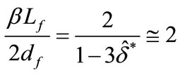
as . That means a rising value of the normalized bridging stress is possible in the pull-out phase only if [6].
 with an interfacial shear stress constant (i.e.
 ), the result would have been:
 (30)
(30)
where g is the snubbing coefficient and
 (31)
(31)
This relation will be used in our model, as the influence of the hardening parameter β is generally negligible in the debonding phase.
4.4. Composite Ultimate Tensile Stress
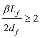
For what we pointed out above, there is a value of the parameter beyond which the bridging stress vs crack opening shows a rising branch whose value is around 2. [5]. Thus, if the parameter (bLf)/2df is smaller than 2, the maximum bridging stress occurs at  that is equivalent to state the following:
 (32)
(32)
for the model with linear hardening interfacial shear stress, or
 (33)
(33)
for the model with constant interfacial shear stress, while for (bLf)/2df > 2 equivalent to state the following:
 (34)
(34)
for the model with linear hardening.
5. Analysis of a FRC Cross Section under a Bending Moment after Crack Opening
In the previous section we faced the problem of randomly oriented fibers debonding and pull-out from a cementitious matrix. We also found the stresses transmitted by the fiber after matrix cracking, relating to the various phases of crack opening. However, we have not yet dealt with the process that leads to define the crack width and its opening as forces acting on the cross section increase. For this purpose, a post crack analysis will be conducted on a specimen that undergoes a four-point bending test comparing the theoretical results relative to load vs deflection and moment vs curvature will be compared to

the test data. In this analysis, the crack bridging law for synthetic fiber in FRC presented in the last chapter will be considered.
5.1. Models for Post Cracking Behavior and Preliminary Assumptions for the Cracked Beam Analysis
We consider a beam under an increasing bending moment M; until the moment reaches a critical value MCR, the displacements increase nearly linearly with the load and no macro crack has yet occurred. Suddenly there is a jump; that is, without significant load increases, a crack opens and displacements show a considerable increase. In this chapter we consider a cracked realistic configuretion for strains and crack opening, see Figure 6 trying only to study the equilibrium between the stress on the concrete and the stress given by the bridging effect of the fiber. We are going to analyze the model of a beam under a condition of four-point bending. Our goal is to include the fiber bridging stress in the cracked cross section equilibrium, and to estimate this contribution to beam toughness and ductility.
For this purpose the following assumptions are made:
1) The behavior of the beam before cracking is linear elastic; after its cracking for its particular load pattern it is rigid-plastic [9], that is, all the further deformations beyond the elastic limit are only related to the deformation of the cracked cross section.
2) The position crack tip is located in the tensile stress area where the matrix strain reaches the value of
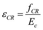 : the strain and the displacements related to the crack opening are both linear along the depth of the cross section. In particular, the crack opening is assumed linearfrom the crack tip to the value of Cmod at the lowest fiber of the cross section.
3) The stress vs strain law of concrete in compression is theparabola rectangle EC2 [9] shown in Figure 7 then
 (35)
(35)

Figure 6. Assumed strains and displacements diagrams in the cracked cross section.
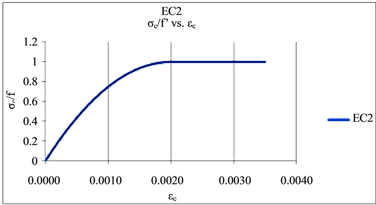
Figure 7. Compressive stress vs strain according EC2 [9].
 (35 bis)
where we assumed 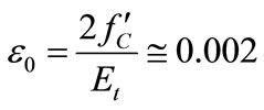 and
and

For concrete tensile stress vs strain, we can assume [8] the relations law is linear
 (36)
(36)
 (36 bis)
where E, the Young modulus (tangent to the curve at the 0,0 point) is equal to  and
and  .
.
In this chapter, however, we consider the concrete cracked zone unable to transmit tensile stress, so the post-peak branch is ignored.
4) The process of crack front proceeding can be considered quasi-static, i.e. no dynamic effects are considered.
5.2. Compatibility and Equilibrium Equations for the Cracked Cross Section
If we define the strain at the upper surface of the beam over the neutral axis as εcx and its maximum value as εcf, the displacement of the extreme fiber for this load picture is given by
 (37)
(37)
As Δ0 is equal to the “virtual” overlapping upper cross section fiber in the rigid body motion, [10] we can define the slope semi-angle formed by the crack opening equal to:
 (38)
(38)
where c is the depth of the neutral axis (see Figure 8) and the settlement of the mid-span point is equal to
 (39)
(39)
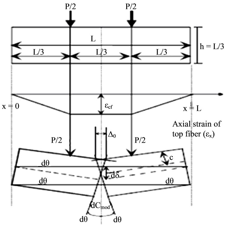
Figure 8. A kinematic mechanism of a fai1ure [10].
plus the elastic deflection, which, according to the EulerBernoulli’s beam theory, is given by
 (40)
(40)
The crack opening is given by (see Figure 8)
 (41)
(41)
The translation equilibrium equation is the following:
 (42)
(42)
while the rotation equilibrium equation is the following
 (43)
(43)
As  in compression and
  in the cracked area we can rewrite the for a rectangular section so
 (44)
(44)
 (44 bis)
while the resultant moment of the compressed concrete with respect to the neutral axis, is equal to
 , (45a)
 (45b)
(45b)
As we assume in c), the concrete is able to transmit tensile stress to where the cross section is not cracked. We can evaluate the tensile concrete stress resultant then
 (46a)
(46a)
Where  is the concrete strain at lowest fiber, and
 , (46b)
The moment of RCT is equal to
 (47a)
(47a)
 (47b)
(47b)
5.3. Resultant of Fiber Bridging Stress
The resultant of fiber bridging stress and its position depends, as we indicate in (3, 27) on crack opening profile. As we can see from Figure 9, three situation can be verified:
1) Cmod corresponds to a normalized crack opening .
.
2) Cmod corresponds to a normalized crack opening .
.
3) Cmod corresponds to a normalized crack opening .
.
where  the normalized maximum crack

Figure 9. Possible bridging stress diagrams in function of the normalized Cmod.
opening.
In 1) the stress resultant is given by:
 (48)
(48)
Then In 2) the stress resultant is made of two terms as the bridging law changes for .
.
Then
 (49)
(49)
where
 (50)
(50)
 (51)
(51)
where 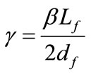
In 3)  where
where remains the same, while
 (52)
(52)
It is not easy to find the value of Cmod for which the bridging stress reaches its maximum value. However it is clear that for , i.e.
  for a given crack length the contribution of RσB begins to decrease, so does its moment as the arm decreases too.
This means that unless there are concentrated reinforcements (e.g. steel bar), it is likely the crack will begin to propagate rather than the Cmod increasing beyond this value.
The resultant moment with respect to the neutral is given, referring to the same situation 1), 2), 3), by the following relations:
1) 
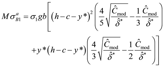 (53)
(53)
2)  there are two components
 (54a)
(54a)
where
 (54b)
(54b)
 (54c)
(54c)
3) 
 (55a)
(55a)
where  and:
and:
 (55b)
(55b)
6. Procedure to Find External Moment vs Curvature Relation in the Cracked Cross Section
In the last paragraph, we defined for a given cross section configuration the stresses resultant and their moment resultant with respect to the neutral axis once we know the upper fiber strain ecf, the neutral axis position c and the crack opening Cmod (cfr. Figure 8).
The parameter Cmod is not independent from the others. In fact, as we showed before, using the rigid plastic model we can define  and
and  [10] and then
 (56)
(56)
So the equation system is defined by two equation in two unknown
 (57)
(57)
 (58)
(58)
and the unknowns are ecf and c. Once we know this parameter, we are able to obtain Cmod and the rigid plastic deflection.
6.1. Equation in the Non-Dimensional Form
The two equilibrium equations can be written using nondimensional terms, avoiding reference to the cross section dimensions. If we divide the first by  and the second by
  setting
 ,
, 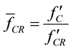 we obtain
 (60)
(60)
where
 ,
, 
 with
with


where the coefficients A, C, D, L, are expressed in Appendix 3 and if no external force is applied to the beam we have

The non-dimensional expression for the moment can be put in the following form;
 (61)
(61)
where  is the. moment due to compressed concrete’
  is the moment due to concrete in tension
  is the moment due to bridging fiber stress where
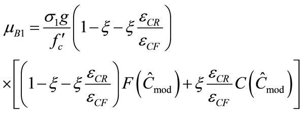 (62)
(62)
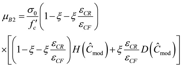 (63)
(63)
The coefficients A, B, C, D, F, H, L, are expressed in Appendix 3.
6.2. Iterative Procedure
The goal of this procedure is to find a link between external moment vs curvature and vs crack opening in the post cracking phase i.e. just after the first crack appears. This procedure operates on equilibrium equation, disregarding the problems related to the crack stability and propagation. The flow-chart is shown in Figure 10. For a given concrete strain in compression at the upper fiber ecf going from 0 to ecu (set equal to −0.0035) with a defined step, a trial position of the neutral axis is assumed (e.g.
 ). Then it is possible to define all the nondimensional resultant and check the equilibrium; if
 then tensile components overcome then it is necessary to increase the neutral axis parameter
 otherwise if
  compression components are prevalent so neutral axis parameter must be decreased then
 . The process can be repeated until a satisfactory convergence is achieved.
The convergence criterion can be focused on the resultant residual i.e.
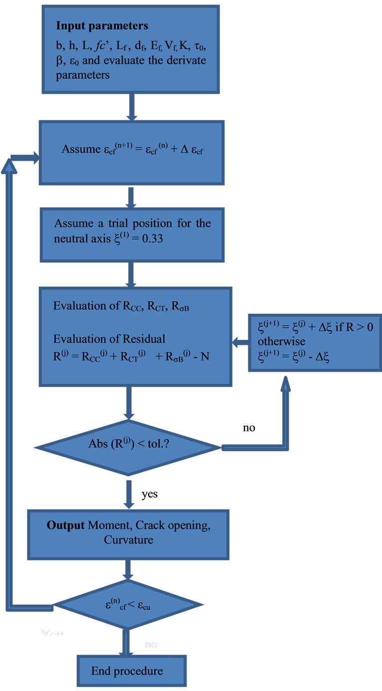
Figure 10. The procedure flow chart.
 where tol. is a tolerance value
(i.e. tol. = 0.01).
If the convergence is achieved it is possible to define an external moment, the crack opening from the Equation (10), and the curvature from the relation
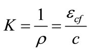 (64)
(64)
Then for a given fiber reinforced concrete beam with given mechanical and geometric properties is possible to obtain a series of data related. Similarly to a reinforced concrete cross section, the ultimate strength and deformation field are defined by geometrical and mechanical parameters, which have to be investigated for every situation depending on fibers length, strength, Young modulus, interfacial stress and volume percentage above all.
The default tolerance is set, for the normalized residual, equal to 10−3, while the incremental step for ecf can be set to Δecf = 0.0001. An important influence in the convergence has the incremental step for ξ, that can be initially set to Δξ = 0.01 but in case of switching sign of the residual R, it could need being reduced (i.e. using bisection method). A simple flow chart is represented in the next page (Figure 10).
6.3. A Numerical Example
A first numerical example will be performed with the model SPECTRA 900 ECC (randomly distributed Spectra fibers in a cement matrix) [3].
According to this article the properties of fiber and matrix are the following

 g = 2 (where g is the snubbing coefficient).
Polyethylene fibers can be untreated and plasma treated; in the second kind the elastic interfacial shear strength is higher (0.8 MPa vs 0.47 MPa). In this numerical test we assume fiber percentage to be 0.75%, that is according to (2) enough to be above the critical percentage.
The other mechanical parameter are summarized in Table 1. The cylindrical compressive concrete strength and the peak tensile concrete strength are obtainable by the following relations
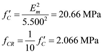
The result in italic font are related to the first crack, assumed to occur, as we mentioned before, when the elastic stress at the lower fiber of the cross section reaches the characteristic tensile strength, assumed, for the cement and concrete matrix, to be around 1/10 of the characteristic cylindrical compression strength. Moment vs crack opening has been plotted for two series, the first is made up of the data related to hardening parameter β = 0.00125 and the second to β = 0. These diagrams will be compared to the similar given by [5].
The numerical simulation is conducted assuming a four point bending test on prismatic specimen 100 × 100 × 350 assuming a span length of 300 mm. The results can be summarized in the Tables 2 and 3.
The result in italic font are related to the first crack,

Table 1. SPECTRA 900 ECC parameters [2].

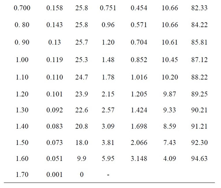
Table 2. Numerical results for SPECTRA 900 untreated τ0 = 0.48 MPa b = 0.0125.
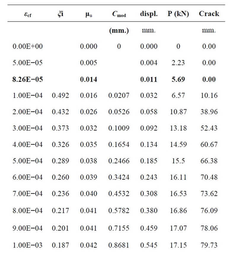
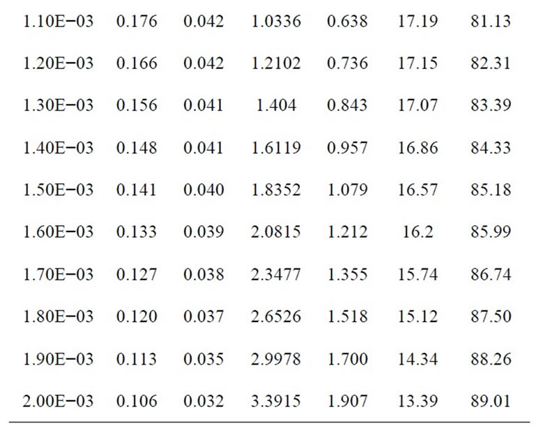
Table 3. Results for SPECTRA 900 ECC plasma treated τ0 = 0.8 MPa b = 0.0128.
assumed to occur, as we mentioned before, when the elastic stress at the lower fiber of the cross section reaches the characteristic tensile strength, assumed, for the cement and concrete matrix, to be around 1/10 of the characteristic cylindrical compression strength.
Moment vs crack opening has been plotted for two series, as shown in Figure 11 the first is made up of the data related to hardening parameter β = 0.00125 and the second to β = 0.
These diagrams will be compared to the similar given by [5] (see Figure 12). As we can see comparing the two diagrams above, even though they refer to little different picture but in any case to the same mechanical properties of the material (the numerical simulation related to Z.
Lin and V. C. Li work is related to a beam with an initial little crack while in our example we assume the central cross section uncracked, in addition the heights are different), the trend external moment vs crack opening is confirmed as the trend of different behavior between the configuration fiber with hardening parameter with respect to the one with fiber the constant shear interfacial stress. In our simulation the initial moment has been obtained assuming linear elastic model until the moment reaches the value of the first crack moment and setting the crack lengths equal to zero.
Even the diagrams load vs displacement of the loaded points (see Figure 13), confirms that, despite the simplicity of assumptions on which this analysis is based on, it is possible to implement the FRC model based on the fiber pull-out in a procedure able to catch the main trends of mechanical behavior in a beam synthetic fiber reinforced cementitious matrix composites element that undergoes an external moment.
7. Conclusions
In this paper, an attempt to link the behavior of a FRC rectangular beam under a four point bending test, has been made. The assumption about a failure configuration
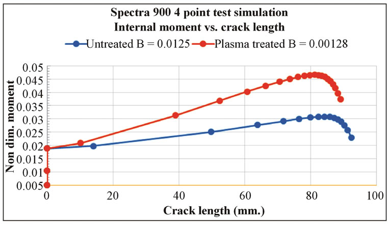
Figure 11. Diagrams moments vs crack length for SPECTRA 900 ECC according the built model.
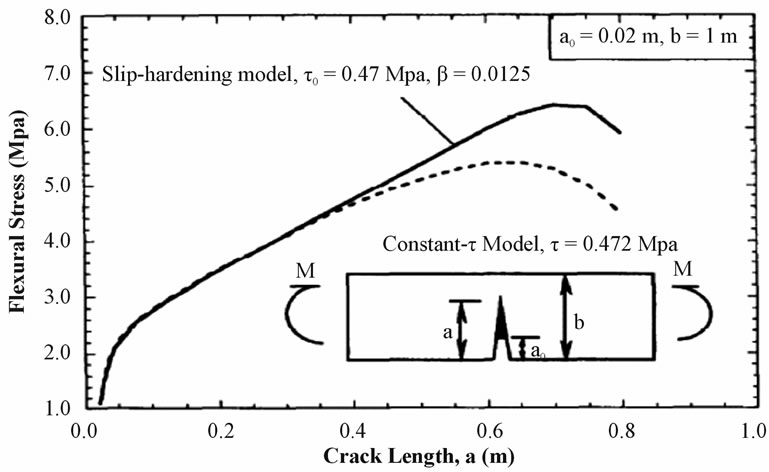
Figure 12. Flexural stress vs. crack length relation of a precracked beam [5].

Figure 13. Load vs displacement of the third points for b = 0 and b = 0.0125.
where a strain pattern for the cross section is consistent with the opening of crack after the maximum tensile stress overcoming reaches the nominal concrete tensile strength allows us to simulate the behavior of a sample of a synthetic FRC sample under increasing flexural load. Despite its simplicity the procedure used in this numerical performance in the previous paragraph is able, for the numerical performance analyzed so far, to catch the trend of the load test behavior as showed in [5].
This present work is not to be considered more than a contribution to developing a model based on the fibers pull-out theories for a better comprehension of fiber reinforced concrete behavior. Obviously further studies must be developed and experimental test must be conducted to confirm the general reliability of this model. In case of a confirmation of the cracking model it can be used to evaluate not only the ultimate strength of a synthetic FRC beam, but also the effect of the main parameters of fibers, like fiber volume fraction, aspect ratio, interfacial shear stress on the toughness and ductility.
8. Acknowledgements
An important contribution to this work has been given by Ph. D. Prechaporn Suwatnodom who gave me most of the needed papers about the FRC topics and for his explanations about the basic concepts. I also want to thank Prof. J. W. Ju for his final review of my Master Thesis, from which most of this work comes from, and Prof. Francesco Federico, always available to give me important suggestions to go on in the research world.
REFERENCES
- P. Suwatnodom, “3D Micromechanical Damage Models, Fiber Pull-Out Models and Fracture Toughness of Discontinuous Steel Fiber Reinforced Cementitious Composites,” UCLA Ph.D. Thesis, 2007.
- N. Banthia, “Micro-Fiber Reinforced Cement Composites,” Indian Concrete Journal, pp. 533-542.
- D. J. Hannant, “Fibre Cements and Fibre Concrete,” John Wiley and Sons, New York, 1978, pp. 219-231.
- L. K. Jain and R. C. Wetherhold, “Effect of Fiber Orientation Composite,” Acta Metallurgica et Materiala, Vol. 40, No. 6, 1992, pp. 1135-1140. doi:10.1016/0956-7151(92)90412-8
- Z. Lin and V. C. Li, “Crack Bridging in Fiber Reinforced Cementitious Composites with Slip-Hardening Interface,” Journal of the Mechanics and Physic, Vol. 45, No. 5, 1996, pp. 763-787. doi:10.1016/S0022-5096(96)00095-6
- Y. Wang, V. C. Li and S. Backer, “Modeling of Fiber Pull-Out from a Cement Matrix,” Journal of Composite, 1988.
- V. C. Li, Y. Wang and S. Backer, “A Micromechanical Model of Tension-Softening and Bridging Toughening of Short Random Fiber Reinforced Brittle Matrix Composites,” Journal of the Mechanics and Physic, Vol. 39, No. 5, 1991, pp. 607-625. doi:10.1016/0022-5096(91)90043-N
- G. Bao and Y. Song, “Crack Bridging Models for Fiber Composites with Slip-Dependent Interfaces,” Solids, Vol. 41, No. 9, 1993, pp. 1425-1444. doi:10.1016/0022-5096(93)90033-C
- Vecchio and Collins, “The Modified Compression-Field Theory for Reinforced Concrete Elements Subjected to Shear,” ACI, Vol. 83, No. 22, 1986, pp. 219-231.
- B. H. Oh, D. G. Park, J. C. Kim and Y.C. Choi, “Experimental and Theoretical Investigation on the Post-Cracking Inelastic Behavior of Synthetic Fiber Reinforced Concrete Beam,” Cement and Concrete Research, Nutritional Aspects of Trace Elements, Vol. 35, No. 2, 2005, pp. 384- 392.
Appendix 1
From compatibility equation.

If we set the origin of the coordinate system z at the tip of the debonded area using the congruence equation and the equilibrium equations
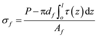

(where l is the debonded length and L is the embedded length).
Appendix 2
Details for resultants of concrete and fiber stresses evaluation on the cross section


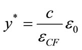
where y* is the distance taken from the neutral axis corresponding to peak tensile stress and to the crack tip, equal to
 .
.


Appendix 3: Non Dimensional Form Coefficients Evaluation

 ,
, 


 and
and 
 and
and 


