Open Journal of Composite Materials
Vol.09 No.02(2019), Article ID:92164,19 pages
10.4236/ojcm.2019.92013
Enhancing the Mechanical Strength for a Microwave Absorption Composite Based on Graphene Nanoplatelet/Epoxy with Carbon Fibers
Maryam Jahan, Richard Osuemeshi Inakpenu, Kuo Li, Guanglin Zhao*
Physics Department, Nano Catalysts Laboratory, Southern University and A&M College, Baton Rouge, LA, USA

Copyright © 2019 by author(s) and Scientific Research Publishing Inc.
This work is licensed under the Creative Commons Attribution International License (CC BY 4.0).
http://creativecommons.org/licenses/by/4.0/


Received: March 29, 2019s; Accepted: April 26, 2019; Published: April 29, 2019
ABSTRACT
Microwave absorption (MWA) materials such as graphene nanoplatelet (GNP)/epoxy are mostly used as coatings on existing structures without considering mechanical properties. In this work, we aim to enhance the mechanical strength of the composite for multifunctional potentials. We used carbon fiber (four layers) to reinforce GNP/epoxy composite (2 mm thick) and investigated their multifunctional properties with GNP loading from 3 to 7 wt%. We measured the tensile strength, hardness, and MW absorption (26.5 - 40 GHz) of composite samples. Our results showed an increase in tensile strength to 109.1 ± 7.9 MPa with 7 wt% GNP in the composite from 15.3 MPa for pure epoxy. The hardness of the composites was also substantially enhanced with GNP loading up to 7 wt%. A MW absorption ratio of 72% was attained for the sample with 7 wt% GNP loading near 40 GHz. The homogenous dispersion of GNPs in the matrix reduces the stress concentration and minimizes the influence of the defects. The high MW absorption and large transmission loss together with enhanced mechanical strength provides a novel multifunctional material for potential applications.
Keywords:
Microwave Absorption, Mechanical Strength, Graphene Nanoplatelet/Epoxy/Carbon Fiber Composite, Multifunctional Composite

1. Introduction
Electromagnetic-wave absorbing (EMA) materials are designed to provide electromagnetic absorption, attenuation, and shielding to protect humans and electronics from external radiation. Wide ranges of applications include satellite communication, TV signal transmission, microelectronic devices, and other applications. Due to rapid growth of electronic industry and electronics devices, electromagnetic interference (EMI) shielding continues to be a serious problem [1] [2] [3]. EMI may interrupt, obstruct, degrade or limit the effective performance of electronics and electrical equipment. External signals or internally generated ones can create stray signals or noise.
Conventionally, in EMI shielding applications, mostly metal-based screening materials were used due to their high electrical conductivity [4]. Traditional EMA materials such as ferrites provide sufficient EMA shielding in many fields. Ferrites composed of ferrous oxide are used to suppress EMI and reduce high-frequency noise levels induced by electromagnetic devices. However, ferrites are heavy and tend to be corroded. There is a continuous demand for the development of effective EMA materials in commercial and civilian applications. Many different materials such as carbon nanotubes (CNTs) [5] [6] , carbon nanoparticles (CNPs) [7] have showed their potentials in the field of MWA applications.
In comparison to metals, carbon composites EMI shields are advantageous because they are characterized by low specific weight, high corrosion resistance, simple, and low-cost processing methods.
Traditionally, EMA materials were mostly used as coatings on existing structures. They increased the weight of the structures. In addition, the mechanical properties of the coating materials were not a critical concern, since the aim of the coating was to enhance MWA.
The aim of this work is to improve the mechanical properties of some MWA composites for developing a multifunctional material, which could offer both MWA and mechanical strength.
Graphene nanoplatelet (GNP), made of several graphene layers stacked together, has a lower production cost and better stability as compared to graphene. Because of the excellent electrical, mechanical and thermal properties of graphene, the resulting nanocomposites can be made electrically conductive with improved heat conductance and stiffness [8] [9] [10]. GNP can also be one of those materials possessing the potential as an advanced material for microwave attenuation and EMI shielding applications. It is expected that graphene and GNPs with large aspect ratio and high intrinsic electric conductivity could render great improvement for the MWA of their composites [11] - [17].
In addition, GNP edges offer the anchor sites for improved dispersions to modify polymer composite properties. The MWA of a composite material is usually believed to depend on relative complex permittivity and permeability, impedance mismatch condition, intrinsic characteristics of filler and electric conductivity of the composites [18]. Bai et al. reported that chemically reduced graphene in poly-(ethylene oxide) composite (2.6 vol.%) showed high MWA capacity [19]. Liang et al. showed that the grapheme-epoxy composites exhibited high EMI shielding effectiveness (SE) over a frequency range of 8.2 - 12.4 GHz (X-band) and a maximum 21 dB shielding efficiency was obtained for the composite with 15 wt% graphene loading [20].
Chen et al. reported the development of a lightweight and flexible graphene-foam composite with outstanding EMI SE as high as 30 dB in 1.5 MHz - 30 GHz frequency range and 20 dB in the X-band frequency range [21]. Wang et al. [22] reported the minimum reflection loss of GNP-epoxy composites reached −14.5 dB at 18.9 GHz with 15 wt% GNP loading. Further increasing GNP loading, the minimum reflection loss of the composites actually decreases, e.g. with 20 and 30 wt% GNP loadings, the minimum reflection loss became −11.2 dB at 17.2 GHz and (−9 dB) at 13.2 GHz, respectively. Liang et al. tested EMI shielding effectiveness on graphene-epoxy composites over a frequency range of 8.2 - 12.4 GHz (X-band). They achieved 21 dB shielding efficiency for 15 wt% loading of graphene at 8.2 GHz [20]. A chemically reduced graphene (2.6 vol.%) in poly-(ethylene oxide) composite exhibited high MWA capacity [19].
In order to make aircrafts more fuel efficient, the material used for their fabrication needs to be lighter. Carbon-filled polymer composites are lighter than metals, and have the potential to be just as strong as metals. Thus, finding a GNP/polymer composite with high MWA capacity and suitable mechanical properties is an attractive subject. The aim of this work is to improve the mechanical properties of some MWA composites for developing a potentially multifunctional material, which could offer both MW absorption and mechanical strength. To the best of our knowledge, very few experimental or theoretical works have explored these multifunctional properties of GNP composites for enhanced mechanical and MWA properties. In this work, we fabricated GNP/epoxy composites reinforced by using carbon fibers (CFs). We investigated the tensile strength, hardness, and MWA properties in a frequency range of 26.5 - 40 GHz for these composites. The composites show a good MWA with acceptable mechanical property, which may have the potential as a light weight EMI shielding structure material without a need of additional coating.
2. Experimental
2.1. Materials
3K plain weave CF fabrics were obtained from Fiber Glast Development Corp. (Ohio, USA). GNP powders were acquired from Cheap tubes Inc., USA. The GNPs are made by dry plasma exfoliation of graphite, friable to 4 atomic layers with an average thickness of 8 nm. The epoxy matrix used in this experiment consists of an epoxy resin #300 and a non-blushing cycloaliphatic Hardener #21, supplied by Aero Marine Products Inc. USA. MS-122AD release agent acquired from Miller-Stephenson Inc. USA is specially used for releasing composite from the sample mold.
2.2. Fabrication Process
The GNP/CF/epoxy composites were fabricated by a laying up process. First, 3 -7 wt% loading fraction of GNPs were mixed with epoxy resin (Aero Marine #300) in a beaker. A hot plate magnetic stirring machine was used to carry out this mixture for one hour at 120 rpm and at a temperature of 90˚C. The purpose of using a relatively high temperature was to reduce the viscosity of the epoxy for a more homogenous dispersion of GNPs in the epoxy resin. After the mixture was allowed to cool down, Aero Marine hardener #21 with half the mass ratio of epoxy resin was added to the mixture and stirred carefully for about 10 minutes to avoid introducing air bubbles. Then the CF fabric is cut to the length (177.8 mm) and width (25.4 mm) of the rectangular mold used. Release agent (MS 122 AD) was sprayed onto the sample molds and allowed to dry for 15 minutes. This action would aid the removal of the sample from the mold after it has been cured. Finally, the hand lay-up method was employed. In this method, the GNP/epoxy mixture solution was injected into the sample mold and four plies of CF fabric were manually impregnated into the matrix solution in the mold. The mold with its content was then transferred to an oven for curing at 75˚C for 12 hours. The sample was removed from the oven and allowed to cool for another 12 hours (Schematic view). We fabricated five groups of the composite samples: 1) epoxy and hardener resin only; 2) CF/epoxy composite without GNP; 3) 3 wt% GNPs/CF/epoxy composites; 4) 5 wt% GNPs/CF/epoxy composites; and 5) 7 wt% GNPs/CF/epoxy composites.
2.3. Material Testing System (MTS)
Tensile strength measurements were performed on eight specimens for each sample group according to ASTM D3039 [ASTM D3039/D3039M-00, American Society for Testing Materials standards] [23]. A MTS test machine (Model QTEST 150) equipped with a 150 KN load cell as shown in Figure SI-1 was used. This floor instrument consists of two parts: the load frame and the Elite control system. Computer workstation and Testworks software are coupled with this instrument. The composite laminate was inserted into the grip jaws of the load frame section of the equipment while the Elite control system was used to control the movement of the load cells in upward and downward direction when needed. The results and data from the testing machine were displayed on the computer workstation using the Test works 4 software, which is a versatile software and simplifies test setup and increases test data reliability and repeatability. From each composite laminate, rectangular shaped tensile specimen (dimensions: 177.8 mm in length, 25.4 mm in width, and 2 mm in thickness) were
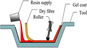
Schematic view. Graphene nanoplatelets (GNP)/Carbon fiber (CF)/epoxy composites were fabricated by a laying up process.
fabricated. The tabs, which are glass fibers/epoxy laminate, were bonded at the ends of the specimens for the tensile strength measurement. Figure SI-2 shows the images of the eight specimens used for tensile testing. The tensile tests were performed at a constant head-speed of 2.0 mm/min until the specimen fails. The tensile measurement was done at room temperature. Cross-sectional area 50.8 mm2 of the sample was available for tensile test for each specimen. The dimension of the specimens, materials used for bonded tabs and constant head speed of the test machine followed the recommendations from the standard method of ASTM D3039.
The equation used to calculate the tensile strength according to ASTM 3039 is
where:
Ftu = ultimate tensile strength, MPa.
Pmax = maximum load before failure, N.
A = average cross-sectional area, mm2.
2.4. PNA-L Network Analyzer
Figure SI-3 shows the Agilent 2-port N5230 C PNA-L microwave network Analyzer (Agilent Company, USA). This instrument was used to measure the microwave scattering parameters (S-parameters) and a 85071E material measurement software was used to analyze the MWA properties. A waveguide method was used for the measurement of the MWA properties in the frequency range from 26.5 to 40 GHz for the composite samples (size: 2 mm in thickness, 7.0 mm in length, and 3.5 mm in width), which were cut from each group of the samples after tensile test. Measurements were done at room temperature. Microwave signal is incident on the composite sample, part of the signal is reflected, and some of it is absorbed as heat by the material while the rest is transmitted to the other port. The scattering parameters were used to compute the absorption properties for the microwave analysis.
2.5. TEM and SEM
Transmission electron microscope (TEM) (JEM-1400) with an acceleration voltage of 120 kV was used to record the images of the sample for microscopic structure analysis. This model features high resolution and excellent TEM analytical performance, and a simplified graphical user interface (GUI) with multi-touch screen for maximum ease of use. For all samples, scanning electron microscopy (SEM) images were taken with (JSM-6610LV, JOEL. Japan, at voltage 15 kV) equipped with energy-disperse secondary analysis system (EDS) (EDAX, USA).
2.6. Hardness Test
The hardness test was carried out using a Hardness machine (LECO Corporation, Michigan, USA). According to ASTM D 785 standard, the specimens were prepared for Rockwell-B hardness test. Indenter was 1/16-inch-diameter (1.588 mm) steel sphere with preliminary force of 98.06 newtons (10 kg-force) and total force 980.6 newtons (100 kg-force) for Scale B measurements. The specimen size was 25 mm in width, a length of 50 mm, and thickness at 2 mm. First, the specimen was cleaned to remove impurities and irregularities. The test was performed on the side that had the best smoothness and homogeneous surface. The tests were done on flat surfaces to ensure good seating on the anvil and thus avoid the deflection that may be caused by poor contact. The specimen was placed on a hard, horizontal surface. The durometer was held in a vertical position to the sample surface. For each specimen, we performed 20 hardness tests and took the average values in the report. Tests conducted in laboratory atmosphere of 23˚C [73.4˚F] and 50% relative humidity.
3. Results and Discussion
X-ray diffraction (XRD) patterns of GNP and graphite powders are shown in Figure 1(a). The sharp peak at 2θ = 26.2˚ is the characteristic diffraction signal from graphitic interlayers (002). The peaks at 42.20, 44.35 and 56.61 of 2θ were assigned to the (100), (101) and (004) planes, respectively [24] [25]. The broadening of the peaks around 26.2˚ and 44˚ in GNP sample is due to the decreased graphitic particle sizes. Figure 1(b) shows the TEM images of typical GNP powder. It is seen that the GNP consists of a few stacked graphene layers. The average size of GNP is a few hundred of nanometers. Figure 1(c) shows the SEM image of the untreated CF, which has a smooth and neat surface. After addition of GNPs, Graphene nanoplatelets are grafted onto the CF surface in the composite and increase CF surface roughness (Figures 1(d)-(g)). The influence of the presence of GNPs in the CF/epoxy matrix has been examined in two different categories: 1) mechanical properties including tensile strength and hardness; 2) MWA and transmission properties.
3.1. Mechanical Properties
3.1.1 Tensile Test
For the tensile test, failure modes and locations of the specimen were photographed and recorded after tensile testing in accordance to the ASTM D3039 [23]. A standard three-part failure mode code is used to analyze the tensile test failure, which was based on the characteristics of type, area and location as shown in Table SI-1, Table SI-2 and Table SI-3. The tensile strength of eight specimens for each sample group obtained from mechanical tests and their corresponding failure modes are shown in Table 1. Table 1 also shows the mean values with standard deviation of the tensile strength for each composite group. All composite samples have four layers of 3K plain weave CF fabric in 2 mm thickness. As a comparison, the data of the tensile strength of pure epoxy with hardener is also included in Table 1.
Table 1 shows that the tensile strength of pure epoxy is quite low at about 15.3 MPa. Introducing four layers of CF into the epoxy resin, the tensile strength of the CF/epoxy composite was drastically increased to about 85.9 MPa, leading to a factor of 5.6 increments. When 3 wt% GNPs were added to the composite, tensile strength was further increased to about 94.3 MPa, or about 10.7% increment as compared with CF/epoxy composite sample. The measured tensile strength values of 3 wt% and 5 wt% GNP/CF/epoxy composites are within the range of experimental error, i.e. the tensile strength did not change by increasing the GNP loading from 3 to 5 wt%. The 7 wt% GNP/CF/epoxy composite showed an enhanced tensile strength to 109.1 MPa with four layers of 3K plain weave CF fabric in the composite (2 mm thickness). This is seven times larger than pure epoxy and about 1.2 times higher than CF/epoxy composite. However, by using more layers of CF in the composite can enhance the mechanical strength, but will decrease the value space for GNP and reduce the MWA performance. As this consideration, we did not use more than four layers of CF in the composite.

Figure 1. (a) XRD patterns of GNP and graphite powders, (b) TEM image of GNP powder. SEM images (c) untreated CF, (d) 3% GNP modified composite sample, (e) 5% GNP modified composite, (f and g) 7% GNP modified composite.

Table 1. Results obtained for tensile tests on the composites.
The tensile strength of polymer composites also depends on the properties of nanoparticle-matrix interaction, in addition to the CF fabric used in the composites. For example, when the particle size decreases to the nanoscale, the specific surface area rapidly increases, making the surface properties as the dominant factors. The properties of interphase between nanofiller and matrix play an important role in the level of dissipated energy by different damaging mechanisms which take place at the nanoscale [26] [27]. Consequently, addition of 7 wt% of GNPs with nano-scaled particles improved the tensile strength of CF/epoxy matrix. On the other hand, the increase in tensile strength can be attributed to the primary components of CF and GNP. CF is known for its high strength and stiffness in tension and GNP exhibits outstanding mechanical performance. Also, the strong bonding of CF and GNPs with the epoxy matrix as shown in Figures 1(d)-(g) contributes to the mechanical enhancement.
The addition of GNPs to the composite increases the crack propagation resistance of the matrix and the interfacial stress transfer between CF and matrix during tensile testing [28]. In addition, the homogenous dispersion of GNPs in the matrix reduces the stress concentration and minimizes the influence of the defects. All specimens/tab bonded regions of the specimen were evaluated after tensile testing. It was observed that no failure occurred due to shear or deboning in the interface between composite and laminate tabs. Although, some specimens presented failure close to the tab, but none showed adhesion failure or CF pull-out. Pictures of the specimen after tensile tests with valid failure modes as classified in ASTM 3039 standard are shown in Figures SI 4-10.
Figure 2 illustrates the typical stress-strain behavior of pure epoxy and the composites with increased loading of GNPs under tensile test. Introducing CF or GNPs into the composite, the tensile behavior of the samples apparently exhibit different levels of enhancing trend when compared to the baseline pure epoxy. We could infer that 7 wt% GNP/CF/epoxy composite demonstrates better stiffness and toughness as compared to other samples. The GNP/CF/epoxy composites imparted a brittle failure shown by the sudden drop in the load after attaining the peak load and a decrease in load, while a ductile manner was exhibited by pure epoxy.
3.1.2. Hardness Study
We extended our investigation on the improvement of mechanical properties of the composites upon the addition of GNPs. The hardness of the composites was also studied by applying an indentation load normal to the surface. The effect of GNP loading on the Rockwell B hardness of the materials illustrated in Figure 3. Additions of GNPs to the composites substantially enhanced the hardness property of the composites.

Figure 2. The stress-strain curves obtained from the tensile tests of pure epoxy and composites.

Figure 3. Hardness of pure epoxy, CF/Epoxy composite, and the composites with 3%, 5%, and 7% GNP.
Figure 3 illustrates the variation of Rockwell B hardness of the composite materials. CF reinforced epoxy exhibits an increased hardness as compared to that of pure epoxy. The composite with 3 wt% GNPs shows 39% increase in the hardness as compared to CF/Epoxy. As shown in Figure 3, further increasing GNP loadings to 5 and 7 wt%, the hardness of GNP/CF/Epoxy composites increase by 55% and 68% as compared to CF/Epoxy, respectively. The increase in the hardness indicates the synergetic effect of GNPs in the composite. Hardness tests show that the composite with the 7 wt% GNP content has the highest hardness value, a trend similar to the tensile strength improvement upon the addition of GNP.
Hereupon, modifying epoxy materials with the integration of nanofillers as a second micro phase can improve the resistance to crack initiation which activates during the curing treatment process. This combination exhibits a high strength, low density, high stiffness, high hardness, and low cure shrinkage [29] [30] [31] [32]. GNP acting as a nanofiller contains tightly packed carbon atoms with a combination of the σ- and π-bonds which has strong stability [33] , with an intrinsic tensile strength of 130 GPa and a Young’s modulus (stiffness) of 1 TPa (150,000,000 psi) [33]. GNP has a high specific surface area which can increase the contact surface area between epoxy and graphene nano plates resulting in an improvement of the mechanical properties of this hybrid composites [34]. Large contact areas tend to decrease interfacial resistance between nanofillers and matrix materials rendering high strength and hardness [35]. Furthermore, not only GNP can improve the mechanical properties of epoxy, but also it can enhance the interfacial interaction between CF and the matrix. The untreated CF has shown in Figure 1(c) has a smooth and neat surface. Addition of GNP can cause CF surface roughness due to grafting Graphene nanoplatelets onto the CF surface (Figures 1(d)-(g)). This can significantly increase interfacial bonding strength by increasing the fiber surface area and enhancing mechanical interlocking between the fibers and the epoxy matrix [36] [37]. Due to the π-π conjugated electronic structure in graphene sheet, graphene can act as nuclei of hydrocarbon molecules [38]. Specifically, the sp2 hybridization formed big π orbitals attract similar structured small polyaromatic molecules by Van Der Waals forces in the direction that vertical to the surface of graphene [38]. It means that graphene sheet on the surface of CFs can induce the ordered deposition of pyrocarbon (high texture matrix) around CFsurfaceleading to enhancements in the resistance of micro-cracks in the interface and matrix [38]. Furthermore, the number of de-bonded fiber-matrix regions around matrix cracks can be reduced after the addition of GNP, that leads to improvement in the fiber/matrix interface bonding strength of the composite and higher tensile strength and hardness of the sample.
3.2. Microwave Absorption Properties of the GNP/Epoxy/CF Composites
The MWA properties of composites depend on various factors such as complex permittivity, permeability, electric conductivity, and the condition of impedance mismatch of the composite [18]. When microwave signal is incident on the surface of a material, some of its energy is reflected, absorbed, and transmitted. The absorbed energy creates a heating effect in the material, when the electromagnetic field interacts with the atoms and molecules in the material [39]. In this work, we used a vector network analyzer (Agilent N5230c, USA) and 85071E material measurement software to study the MWA properties of the composite. The absorbance (A) also known as the absorption ratio, is calculated from the measured scattering parameters. The absorption ratio is a measure of the MWA capability of the material. The higher the absorption ratio, the better the MWA ability of the material is. In this work, we obtained the absorption ratio of the GNP/CF/epoxy composites samples to the microwave radiation over a continuous frequency range of 26.5 - 40 GHz.
Figure 4(a) shows the dependence of MWA ratio of the GNP/CF/epoxy composites over the frequency range of 26.5 - 40 GHz. The thickness of the samples is 2 mm. The absorption ratio of the composites was significantly improved as the GNP loadings increase in the composites. The MWA capability of pure epoxy is very low. The CF/epoxy without GNP composite has a steady absorption over a short frequency range from 26.5 to 31.1 GHz. The absorption ratio reaches a peak of 36.5% at 31 GHz for the CF/epoxy composite. However, the GNP/CF/epoxy composites with 3 and 5 wt% GNPs produce an absorption ratio about 41% and 51% in a narrow frequency range of 33.5 - 36.5 GHz. For the composite sample with 7 wt% GNP loading, the absorption ratio shows a stronger frequency dependence. The absorption ratio is 43.5% at 26.5 GHz. It increases to 60.5% at 33 GHz and finally attains a maximum of 72% at ~40 GHz. It is noticed that a wide MWA bandwidth was realized over a frequency range of 26.5 - 40 GHz.
Figure 4(b) shows the frequency dependence of microwave transmission for pure epoxy, CF/epoxy without GNP, and GNP/CF/epoxy composites with different GNP loadings. It was evaluated from the S-parameters in the microwave measurement for the composites and can be described as below:
where Pt(Et) and Pi(Ei) are the power (electric field) of transmitted and incident microwave waves, respectively. The negative sign in dB in the transmission represents a transmission loss (or shielding effectiveness (SE)) by the composite material to the microwave signal. Pure epoxy shows very low MWA and high microwave transmission (or low microwave shielding effectiveness (SE)). On the contrary, the CF/epoxy and GNP/CF/epoxy composites show very low microwave transmission, lower than −20 dB in a wide bandwidth from 26 to 40 GHz. A transmission loss of −10 dB corresponds to 90% of EM wave reduction in transmission and is considered as effective for some applications. A transmission loss of −20 dB corresponds to 99% of EM wave transmission reduction. These results demonstrated that these composites show high microwave shielding effectiveness and could be used for various applications. Although metals can also be used as shielding materials, they cannot offer MWA character. Since the microwave reflection from metal surface is high, the reflected electromagnetic wave can cause stray signals, which produce noises and EM wave pollution, that can affect measurement sensitivity. Due to not being able to absorb EM wave from metals effectively, humans have to tolerate the excessive EM wave pollution. On the other hand, our composite has a high absorption of EM wave signals, consequently the noise is suppressed and electromagnetic interference will be reduced, in addition to the high microwave shielding effectiveness of the composites. Furthermore, the composite has a low mass density (about 1.7 g/cm3), much lighter than that of metals.
The MWA properties of the GNP/CF/epoxy composites are mainly attributed to their dielectric loss because the materials are not magnetic. When an external EM wave interacts with charge multipoles at the polarized interfaces between epoxy and GNP particles, the microwave radiation is attenuated and consequently contributes to the MWA in the composite. Therefore, GNPs can provide a myriad number of electrical pathways which dissipate microwave energy into heat efficiently. In addition, the vast interfaces of GNPs/epoxy can induce dielectric relaxation and interface scattering in the composite.

Figure 4. (a) The microwave absorption ratio of GNP/CF/epoxy composite samples with GNP loading fractions from 3 - 7 wt% and composite without GNP. (b) The microwave transmission (in dB) of the composite samples.
4. Conclusion
In this work, we fabricated GNP/CF/epoxy composites with GNP loadings from 3 to 7 wt%, CF/epoxy composite and pure epoxy. The measurement results show that the tensile strength of the GNP/CF/epoxy and CF/epoxy composites strongly depends on the CF (four layers used in this work) and the GNP loading. The tensile strength of 109.1 ± 7.9 MPa was obtained for the sample with 7 wt% GNP loading and four plies of CF fabric (Figure S11). In addition, the hardness of the composite has been improved upon addition of GNP content. The mechanical and hardness tests show that the composite with a high (such as 7 wt%) GNP content improves the mechanical strength of the texture due to the improvement of the bonding of CF to the matrix causing the enhancement of microcrack resistance in the matrix interface. We also investigated the MWA and transmission properties of the GNP/CF/epoxy and CF/epoxy samples. The 7 wt% GNP composite sample shows high absorption ratio over a wide frequency range of 26.5 - 40 GHz. The MWA is mainly due to high dielectric loss, interfacial electric polarization, and free electric charge in the composites. In addition, based on the large transmission loss, these composites show high microwave shielding effectiveness. This suggests that the composite has the potential for multifunctional applications that require wide bandwidth MWA and shielding effectiveness as well as high tensile strength and hardness. These multifunctional properties may differentiate this composite with other similar materials rendering a novel multifunctional material for potential applications.
Acknowledgements
The work was funded in part by the National Science Foundation (NSF) CREST project (Award No HRD 1736136) and the Army Research Office (ARO) (Award No W911NF-15-1-0483) in the United States.
Conflicts of Interest
The authors declare no conflicts of interest regarding the publication of this paper.
Cite this paper
Jahan, M., Inakpenu, R.O., Li, K. and Zhao, G.L. (2019) Enhancing the Mechanical Strength for a Microwave Absorption Composite Based on Graphene Nanoplatelet/Epoxy with Carbon Fibers. Open Journal of Composite Materials, 9, 230-248. https://doi.org/10.4236/ojcm.2019.92013
References
- 1. Wong, K., Pickering, S. and Rudd, C. (2010) Recycled Carbon Fibre Reinforced Polymer Composite for Electromagnetic Interference Shielding. Composites Part A: Applied Science and Manufacturing, 41, 693-702. https://doi.org/10.1016/j.compositesa.2010.01.012
- 2. Pawar, S.P., Biswas, S., Kar, G.P. and Bose, S. (2016) High Frequency Millimetre Wave Absorbers Derived from Polymeric Nanocomposites. Polymer, 84, 398-419. https://doi.org/10.1016/j.polymer.2016.01.010
- 3. Wang, W., Li, W., Gao, C., et al. (2015) A Novel Preparation of Silver-Plated Polyacrylonitrile Fibers Functionalized with Antibacterial and Electromagnetic Shielding Properties. Applied Surface Science, 342, 120-126. https://doi.org/10.1016/j.apsusc.2015.01.188
- 4. Los, P., Lukomska, A. and Jeziorska, R. (2016) Metal-Polymer Composites for Electromagnetic Interference Shielding Applications. Polimery-Warsaw, 61, 663-669. https://doi.org/10.14314/polimery.2016.663
- 5. Jia, L.-C., Yan, D.-X., Cui, C.-H., et al. (2015) Electrically Conductive and Electromagnetic Interference Shielding of Polyethylene Composites with Devisable Carbon Nanotube Networks. Journal of Materials Chemistry C, 3, 9369-9378. https://doi.org/10.1039/C5TC01822F
- 6. Li, N., Huang, Y., Du, F., et al. (2006) Electromagnetic Interference (EMI) Shielding of Single-Walled Carbon Nanotube Epoxy Composites. Nano Letters, 6, 1141-1145. https://doi.org/10.1021/nl0602589
- 7. Eswaraiah, V., Sankaranarayanan, V., Mishra, A.K. and Ramaprabhu, S. (2010) Electromagnetic Interference (EMI) Shielding of Carbon Nanostrcutured Films. International Conference on Chemistry and Chemical Engineering, Kyoto, 1-3 August 2010, 150-152. https://doi.org/10.1109/ICCCENG.2010.5560383
- 8. Stankovich, S., Dikin, D.A., Dommett, G.H., et al. (2006) Graphene-Based Composite Materials. Nature, 442, 282. https://doi.org/10.1038/nature04969
- 9. Thostenson, E.T., Li, C. and Chou, T.-W. (2005) Nanocomposites in Context. Composites Science and Technology, 65, 491-516. https://doi.org/10.1016/j.compscitech.2004.11.003
- 10. Kim, H., Abdala, A.A. and Macosko, C.W. (2010) Graphene/Polymer Nanocomposites. Macromolecules, 43, 6515-6530. https://doi.org/10.1021/ma100572e
- 11. Skulason, H., Nguyen, H., Guermoune, A., et al. (2011) 110 GHz Measurement of Large-Area Graphene Integrated in Low-Loss Microwave Structures. Applied Physics Letters, 99, Article ID: 153504. https://doi.org/10.1063/1.3650710
- 12. Zhang, H.-B., Yan, Q., Zheng, W.-G., He, Z. and Yu, Z.-Z. (2011) Tough Graphene-Polymer Microcellular Foams for Electromagnetic Interference Shielding. ACS Applied Materials & Interfaces, 3, 918-924. https://doi.org/10.1021/am200021v
- 13. Basavaraja, C., Kim, W.J. and Do Kim, Y. (2011) Synthesis of Polyaniline-Gold/Graphene Oxide Composite and Microwave Absorption Characteristics of the Composite Films. Materials Letters, 65, 3120-3123. https://doi.org/10.1016/j.matlet.2011.06.110
- 14. Wang, C., Han, X., Xu, P., et al. (2011) The Electromagnetic Property of Chemically Reduced Graphene Oxide and Its Application as Microwave Absorbing Material. Applied Physics Letters, 98, Article ID: 072906. https://doi.org/10.1063/1.3555436
- 15. Singh, V.K., Shukla, A., Patra, M.K., et al. (2012) Microwave Absorbing Properties of a Thermally Reduced Graphene Oxide/Nitrile Butadiene Rubber Composite. Carbon, 50, 2202-2208. https://doi.org/10.1016/j.carbon.2012.01.033
- 16. Adohi, B., Bychanok, D., Haidar, B. and Brosseau, C. (2013) Microwave and Mechanical Properties of Quartz/Graphene-Based Polymer Nanocomposites. Applied Physics Letters, 102, Article ID: 072903. https://doi.org/10.1063/1.4793411
- 17. Wang, Z., Wei, G. and Zhao, G.L. (2013) Enhanced Electromagnetic Wave Shielding Effectiveness of Fe Doped Carbon Nanotubes/Epoxy Composites. Applied Physics Letters, 103, Article ID: 183109. https://doi.org/10.1063/1.4828356
- 18. Zhang, H., Zhang, J. and Zhang, H. (2006) Numerical Predictions for Radar Absorbing Silicon Carbide Foams Using a Finite Integration Technique with a Perfect Boundary Approximation. Smart Materials and Structures, 15, 759. https://doi.org/10.1088/0964-1726/15/3/011
- 19. Bai, X., Zhai, Y. and Zhang, Y. (2011) Green Approach to Prepare Graphene-Based Composites with High Microwave Absorption Capacity. The Journal of Physical Chemistry C, 115, 11673-11677. https://doi.org/10.1021/jp202475m
- 20. Liang, J., Wang, Y., Huang, Y., et al. (2009) Electromagnetic Interference Shielding of Graphene/Epoxy Composites. Carbon, 47, 922-925. https://doi.org/10.1016/j.carbon.2008.12.038
- 21. Chen, L., Lu, C., Fang, Z., et al. (2013) Infrared Emissivity and Microwave Absorption Property of Sm0.5Sr0.5CoO3 Perovskites Decorated with Carbon Nanotubes. Materials Letters, 93, 308-311. https://doi.org/10.1016/j.matlet.2012.11.117
- 22. Wang, Z., Luo, J. and Zhao, G.L. (2014) Dielectric and Microwave Attenuation Properties of Graphene Nanoplatelet-Epoxy Composites. AIP Advances, 4, Article ID: 017139. https://doi.org/10.1063/1.4863687
- 23. ASTM International (2008) Materials ACD-oC. Standard Test Method for Tensile Properties of Polymer Matrix Composite Materials.
- 24. Parveen, N., Mahato, N., Ansari, M.O. and Cho, M.H. (2016) Enhanced Electrochemical Behavior and Hydrophobicity of Crystalline Polyaniline@ Graphene Nanocomposite Synthesized at Elevated Temperature. Composites Part B: Engineering, 87, 281-290. https://doi.org/10.1016/j.compositesb.2015.10.029
- 25. Wang, Q., Wang, Y., Meng, Q., et al. (2017) Preparation of High Antistatic HDPE/Polyaniline Encapsulated Graphene Nanoplatelet Composites by Solution Blending. RSC Advances, 7, 2796-2803. https://doi.org/10.1039/C6RA26458A
- 26. Zare, Y. (2015) Assumption of Interphase Properties in Classical Christensen-Lo Model for Young’s Modulus of Polymer Nanocomposites Reinforced with Spherical Nanoparticles. RSC Advances, 5, 95532-95538. https://doi.org/10.1039/C5RA19330C
- 27. Zare, Y. and Rhee, K.Y. (2017) Dependence of Z Parameter for Tensile Strength of Multi-Layered Interphase in Polymer Nanocomposites to Material and Interphase Properties. Nanoscale Research Letters, 12, 42. https://doi.org/10.1186/s11671-017-1830-5
- 28. Vautard, F., Fioux, P., Vidal, L., et al. (2014) Use of Plasma Polymerization to Improve Adhesion Strength in Carbon Fiber Composites Cured by Electron Beam. ACS Applied Materials & Interfaces, 6, 1662-1674. https://doi.org/10.1021/am4045663
- 29. Martone, A., Formicola, C., Giordano, M. and Zarrelli, M. (2010) Reinforcement Efficiency of Multi-Walled Carbon Nanotube/Epoxy Nano Composites. Composites Science and Technology, 70, 1154-1160. https://doi.org/10.1016/j.compscitech.2010.03.001
- 30. Zhao, Y., Chen, Z.-K., Liu, Y., et al. (2013) Simultaneously Enhanced Cryogenic Tensile Strength and Fracture Toughness of Epoxy Resins by Carboxylic Nitrile-Butadiene Nano-Rubber. Composites Part A: Applied Science and Manufacturing, 55, 178-187. https://doi.org/10.1016/j.compositesa.2013.09.005
- 31. Zhou, Y., Pervin, F., Rangari, V.K. and Jeelani, S. (2006) Fabrication and Evaluation of Carbon Nano Fiber Filled Carbon/Epoxy Composite. Materials Science and Engineering: A, 426, 221-228. https://doi.org/10.1016/j.msea.2006.04.031
- 32. Wang, X., Jin, J. and Song, M. (2013) An Investigation of the Mechanism of Graphene Toughening Epoxy. Carbon, 65, 324-333. https://doi.org/10.1016/j.carbon.2013.08.032
- 33. Lee, C., Wei, X., Kysar, J.W. and Hone, J. (2008) Measurement of the Elastic Properties and Intrinsic Strength of Monolayer Graphene. Science, 321, 385-388. https://doi.org/10.1126/science.1157996
- 34. Yang, S.-Y., Lin, W.-N., Huang, Y.-L., et al. (2011) Synergetic Effects of Graphene Platelets and Carbon Nanotubes on the Mechanical and Thermal Properties of Epoxy Composites. Carbon, 49, 793-803. https://doi.org/10.1016/j.carbon.2010.10.014
- 35. Yu, A., Ramesh, P., Sun, X., et al. (2008) Enhanced Thermal Conductivity in a Hybrid Graphite Nanoplatelet-Carbon Nanotube Filler for Epoxy Composites. Advanced Materials, 20, 4740-4744. https://doi.org/10.1002/adma.200800401
- 36. Tzounis, L., Debnath, S., Rooj, S., et al. (2014) High Performance Natural Rubber Composites with a Hierarchical Reinforcement Structure of Carbon Nanotube Modified Natural Fibers. Materials & Design, 58, 1-11. https://doi.org/10.1016/j.matdes.2014.01.071
- 37. Zhao, F. and Huang, Y. (2011) Preparation and Properties of Polyhedral Oligomeric Silsesquioxane and Carbon Nanotube Grafted Carbon Fiber Hierarchical Reinforcing Structure. Journal of Materials Chemistry, 21, 2867-2870. https://doi.org/10.1039/c0jm03919e
- 38. Yang, W., Luo, R. and Hou, Z. (2016) Effect of Interface Modified by Graphene on the Mechanical and Frictional Properties of Carbon/Graphene/Carbon Composites. Materials, 9, 492. https://doi.org/10.3390/ma9060492
- 39. Saini, P., Choudhary, V., Singh, B., Mathur, R. and Dhawan, S. (2009) Polyaniline-MWCNT Nanocomposites for Microwave Absorption and EMI Shielding. Materials Chemistry and Physics, 113, 919-926. https://doi.org/10.1016/j.matchemphys.2008.08.065
Supporting Information

Figure SI-1.A picture of MTS QTEST/150 tensile tester for laminate composite.

Figure SI-2.Specimens for tensile measurement.

Figure SI-3.Agilent 2-Port N5230 C PNA-L Microwave Network Analyzer.

Figure SI-4.Failure mode type AGT (Angled Gage Top) of the specimen tested.

Figure SI-5.Failure mode type AGM (Angled Gage Middle) of the testedspecimen.

Figure SI-6.Failure mode type LAB (Lateral At grip/tab Bottom) of the specimen tested.

Figure SI-7.Failure mode type LGM (Lateral Gage Middle) of the specimen tested.

Figure SI-8.Failure mode type LGT (Lateral Gage Top) of the specimen tested.

Figure SI-9.Failure mode type AGB (Angled GageBottom) of the specimen tested.

Figure SI-10.Failure mode type LGB (Lateral Gage Bottom) of the specimen tested.
SI-1. First Character of failure mode code.
SI-2. Second Character of failure mode code.
SI-3. Third Character of failure mode code.

Figure SI-11.Enhanced tensile strength with the addition of GNPs in the composite.
The figure shows that the tensile strength of pure epoxy is quite low at about 15.3 MPa. Introducing four layers of CF into the epoxy resin, the tensile strength of CF/epoxy composite was drastically increased to about 85.9 MPa, leading to a factor of 5.6 increments. When GNPs were added to the composite, tensile strength was further increased to about 100 MPa, as compared with CF/epoxy composite sample.