Paper Menu >>
Journal Menu >>
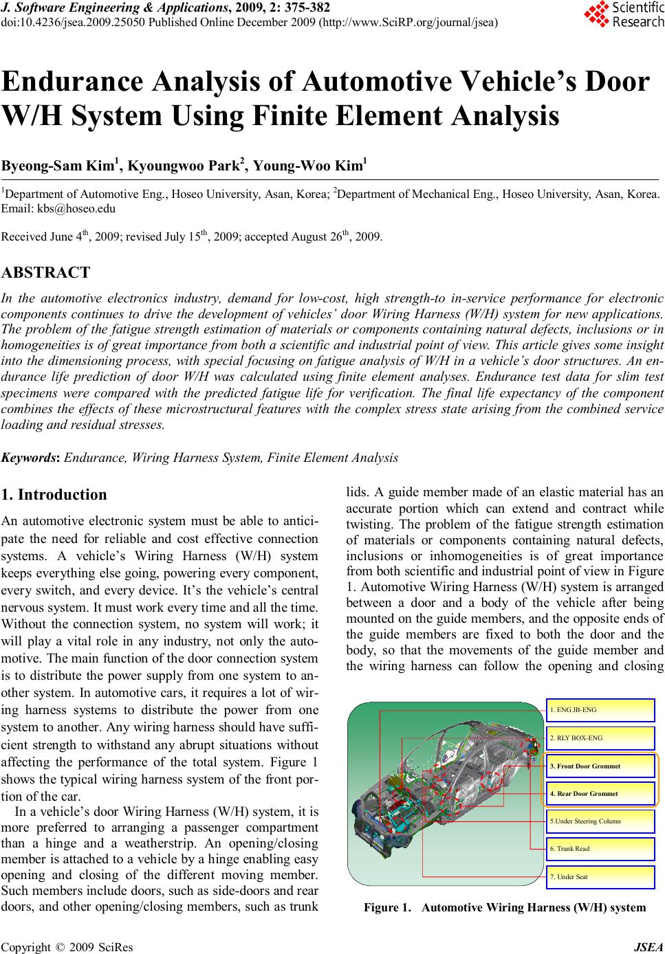 J. Software Engineering & Applications, 2009, 2: 375-382 doi:10.4236/jsea.2009.25050 Published Online December 2009 (http://www.SciRP.org/journal/jsea) Copyright © 2009 SciRes JSEA 375 Endurance Analysis of Automotive Vehicle’s Door W/H System Using Finite Element Analysis Byeong-Sam Kim1, Kyoungwoo Park2, Young-Woo Kim1 1Department of Automotive Eng., Hoseo University, Asan, Korea; 2Department of Mechanical Eng., Hoseo University, Asan, Korea. Email: kbs@hoseo.edu Received June 4th, 2009; revised July 15th, 2009; accepted August 26th, 2009. ABSTRACT In the automotive electronics industry, demand for low-cost, high strength-to in-service performance for electronic components continues to drive the development of vehicles’ door Wiring Harness (W/H) system for new applications. The problem of the fatigue strength estimation of materials or components containing natural defects, inclusions or in homogeneities is of great importance from both a scientific and industrial point of view. This article gives some insight into the dimensioning process, with special focusing on fatigue analysis of W/H in a vehicle’s door structures. An en- durance life prediction of door W/H was calculated using finite element analyses. Endurance test data for slim test specimens were compared with the predicted fatigue life for verification. The final life expectancy of the component combines the effects of these microstructural features with the complex stress state arising from the combined service loading and residual stresses. Keywords: Endurance, Wiring Harness System, Finite Element Analysis 1. Introduction An automotive electronic system must be able to antici- pate the need for reliable and cost effective connection systems. A vehicle’s Wiring Harness (W/H) system keeps everything else going, powering every component, every switch, and every device. It’s the vehicle’s central nervous system. It must work every time and all the time. Without the connection system, no system will work; it will play a vital role in any industry, not only the auto- motive. The main function of the door connection system is to distribute the power supply from one system to an- other system. In automotive cars, it requires a lot of wir- ing harness systems to distribute the power from one system to another. Any wiring harness should have suffi- cient strength to withstand any abrupt situations without affecting the performance of the total system. Figure 1 shows the typical wiring harness system of the front por- tion of the car. In a vehicle’s door Wiring Harness (W/H) system, it is more preferred to arranging a passenger compartment than a hinge and a weatherstrip. An opening/closing member is attached to a vehicle by a hinge enabling easy opening and closing of the different moving member. Such members include doors, such as side-doors and rear doors, and other opening/closing members, such as trunk lids. A guide member made of an elastic material has an accurate portion which can extend and contract while twisting. The problem of the fatigue strength estimation of materials or components containing natural defects, inclusions or inhomogeneities is of great importance from both scientific and industrial point of view in Figure 1. Automotive Wiring Harness (W/H) system is arranged between a door and a body of the vehicle after being mounted on the guide members, and the opposite ends of the guide members are fixed to both the door and the body, so that the movements of the guide member and the wiring harness can follow the opening and closing 1. ENG JB-ENG 2. RLY BOX-ENG 3. Front Door Grommet 4. Rear Door Grommet 5.Under Steering Column 6. Trunk Read 7. Under Seat Figure 1. Automotive Wiring Harness (W/H) system 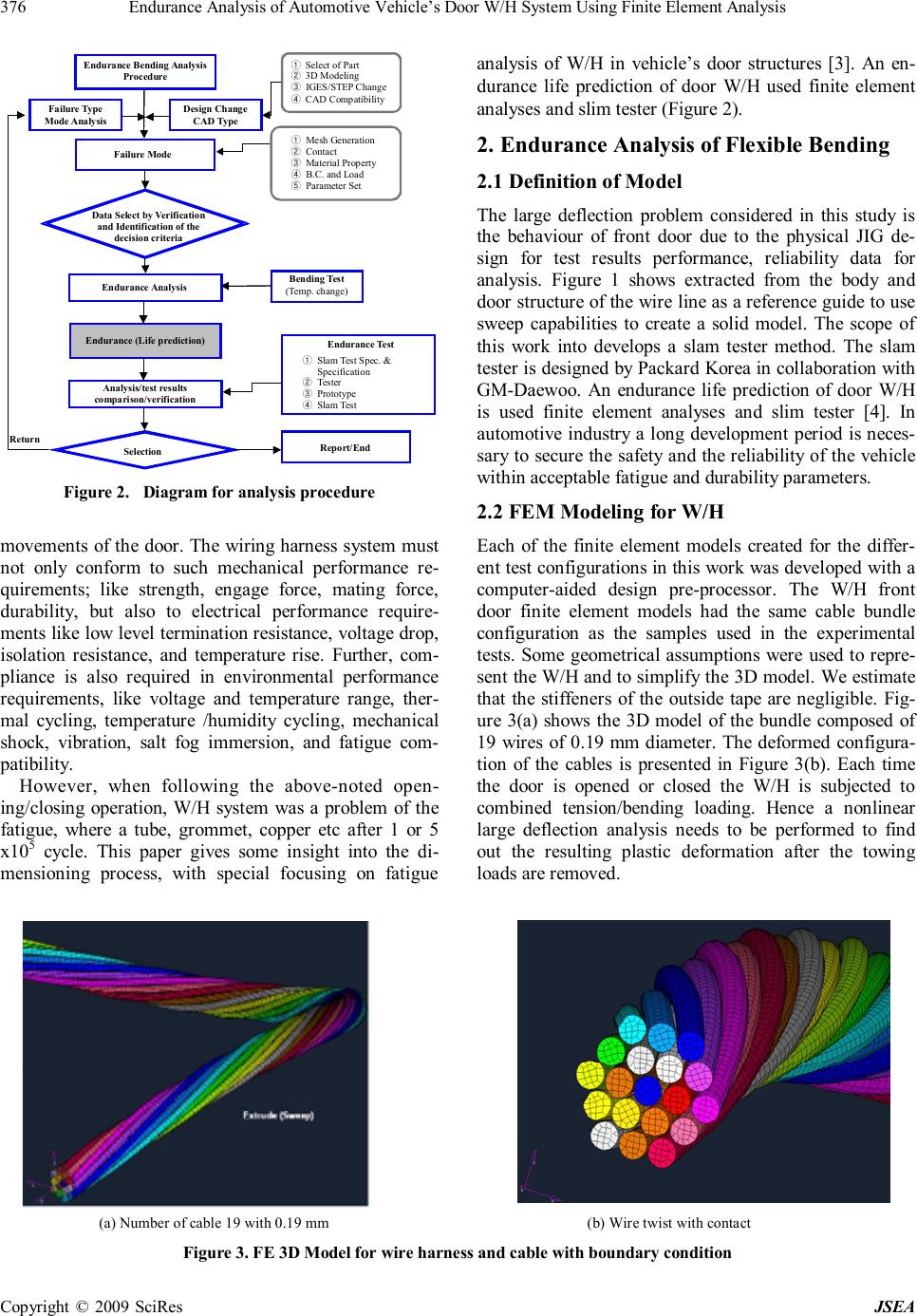 Endurance Analysis of Automotive Vehicle’s Door W/H System Using Finite Element Analysis Copyright © 2009 SciRes JSEA 376 Endurance Analysis Endurance (Life prediction) ① Slam Test Spec. & Specification ② Tester ③ Prototype ④ Slam Test Endurance Bending Analysis Procedure Failure Mode Endurance Analysis Endurance (Life prediction) Analysis/test results comparison/verification Selection Endurance Test Failure Type Mode Analysis Data Select by Verification and Identification of the decision criteria Design Change CAD Type Return Report/End Bending Test (Temp. change) ① Mesh Generation ② Contact ③ Material Property ④ B.C. and Load ⑤ Parameter Set ① Select of Part ② 3D Modeling ③ IGES/STEP Change ④ CAD Compatibility Figure 2. Diagram for analysis procedure movements of the door. The wiring harness system must not only conform to such mechanical performance re- quirements; like strength, engage force, mating force, durability, but also to electrical performance require- ments like low level termination resistance, voltage drop, isolation resistance, and temperature rise. Further, com- pliance is also required in environmental performance requirements, like voltage and temperature range, ther- mal cycling, temperature /humidity cycling, mechanical shock, vibration, salt fog immersion, and fatigue com- patibility. However, when following the above-noted open- ing/closing operation, W/H system was a problem of the fatigue, where a tube, grommet, copper etc after 1 or 5 x10⁵ cycle. This paper gives some insight into the di- mensioning process, with special focusing on fatigue analysis of W/H in vehicle’s door structures [3]. An en- durance life prediction of door W/H used finite element analyses and slim tester (Figure 2). 2. Endurance Analysis of Flexible Bending 2.1 Definition of Model The large deflection problem considered in this study is the behaviour of front door due to the physical JIG de- sign for test results performance, reliability data for analysis. Figure 1 shows extracted from the body and door structure of the wire line as a reference guide to use sweep capabilities to create a solid model. The scope of this work into develops a slam tester method. The slam tester is designed by Packard Korea in collaboration with GM-Daewoo. An endurance life prediction of door W/H is used finite element analyses and slim tester [4]. In automotive industry a long development period is neces- sary to secure the safety and the reliability of the vehicle within acceptable fatigue and durability parameters. 2.2 FEM Modeling for W/H Each of the finite element models created for the differ- ent test configurations in this work was developed with a computer-aided design pre-processor. The W/H front door finite element models had the same cable bundle configuration as the samples used in the experimental tests. Some geometrical assumptions were used to repre- sent the W/H and to simplify the 3D model. We estimate that the stiffeners of the outside tape are negligible. Fig- ure 3(a) shows the 3D model of the bundle composed of 19 wires of 0.19 mm diameter. The deformed configura- tion of the cables is presented in Figure 3(b). Each time the door is opened or closed the W/H is subjected to combined tension/bending loading. Hence a nonlinear large deflection analysis needs to be performed to find out the resulting plastic deformation after the towing loads are removed. (a) Number of cable 19 with 0.19 mm (b) Wire twist with contact Figure 3. FE 3D Model for wire harness and cable with boundary condition  Endurance Analysis of Automotive Vehicle’s Door W/H System Using Finite Element Analysis Copyright © 2009 SciRes JSEA 377 Table 1. Specification of W/H type by Standard AVSS series (unit:mm) Outside Diameter Section Cable bundle /diameter Wire Diameter Thickness of Cable Standard Max Resistance 0.3 7/0.26 0.8 0.3 1.4 1.6 50.2 0.5 7/0.32 1.0 0.3 1.6 1.7 32.7 0.85 19/0.24 1.2 0.3 1.8 1.9 21.7 1.25 19/0.29 1.5 0.3 2.1 2.2 14.9 20. 37/0.26 1.8 0.4 2.6 2.7 9.5 Table 2. Non linear analysis each case Standard Cable Bundle /Diameter Difference depth with door body Case AVSS 7/0.32 50 mm 50+50 mm 50+50+50 mm Case 1 Case 2 Case 3 AVSS 19/0.19 50 mm 50+50 mm 50+50+50 mm Case 4 Case 5 Case 6 2.3 Non-Linear Analysis for Residual Stress The contacts interactions were between the cables. To avoid the out of plane deformation of the 19 wires, they were enveloped by a tube represented by a shell 0.15 mm thickness. The tube material is supposed to be the same as the wires one. The wire material is copper alloy their properties are given by Packard Korea. A rotation is im- posed to the bundle, and represents the opening of the door by 75. This rotation induced two bending/torsion moments of the wires considered. Table 2 shows the dif- ferent configurations corresponding to depth with the door body. ABAQUS v6.6 [5,6] is used to perform the non linear analysis on an IBM A-Pro(dual CPU 2GHz). The Abaqus explicit dynamics procedure performs a large number of small time increments efficiently. An explicit central-difference time integration rule is used; each increment is relatively inexpensive (compared to the direct-integration dynamic analysis procedure available in Abaqus/Standard) because there is no solution for a set of simultaneous equations. The explicit dynamics analy- sis procedure is based upon the implementation of an explicit integration rule together with the use of diagonal (“lumped”) element mass matrices [7–10]. The equations of motion for the body are integrated using the explicit central-difference integration rule [6]. (1)() (1/2)(1/2)() (1)()(1)(1/2) 2 ii NNN iii NNN iiii tt uuu uutu + +− +++ ∆+∆ =+ =+∆ &&&& & (1) where uN N is a degree of freedom and the subscript i refers to the increment number in an explicit dynamics step. The central-difference integration operator is explicit in the sense that the kinematic state is advanced using known values of N i u)2/1( − & and N i u)( & & from the previous increment. The explicit integration rule is quite simple but by itself does not provide the computational effi- ciency associated with the explicit dynamics procedure. The key to the computational efficiency of the explicit procedure is the use of diagonal element mass matrices because the accelerations at the beginning of the incre- ment are computed by 1 ()()() ()() NNJJJ iii uMPI − =+− && (2) where NJ Mis the mass matrix, NJ P is the applied load vector, and NJ I is the internal force vector. A lumped mass matrix was used because its inverse is simple to compute and because the vector multiplication of the mass inverse by the inertial force requires only n opera- tions, where n is the number of degrees of freedom in the model. The explicit procedure requires no iterations and no tangent stiffness matrix. 2.4 Material Properties The tube material is supposed to be the same as for the wires. The wire material is copper alloy their properties are given by Packard Korea [3,4]. The characteristics of the W/H are presented in Table 1. Several factors are very important in the test, but this study was difficult to implement as it did not fit the exclusion, and environ- mental, tolerance criteria of the cable as shown in Table 1. The material properties are used for the W/H is Elasto-Plastic materials.  Endurance Analysis of Automotive Vehicle’s Door W/H System Using Finite Element Analysis Copyright © 2009 SciRes JSEA 378 (a) Stresses distribution (b) Maximum deflection of cable wire Figure 4. Non linear analysis with stress distribution and deflection in case2 (ABAQUS) (a) Stresses distribution (b) Maximum deflection of cable wire Figure 5. Non linear analysis with stress distribution and deflection in case 5 (ABAQUS) Figures 4 and 5 show the difference of depth with front door body. This means that a larger number of ca- bles with wire are not less than the variation mode then it is a lot of more flexible and also stresses that the work can be seen. In addition, if the same contribute with cable larger depth with door body stresses that the work can be found in Table 4. 2.5 Durability Analysis with Flexible Bending The history of cycle loading can be considered as a sine curve and corresponding to opening/closing of the door by 75. Figures 6 and 7 present the damage criteria over the wires. A value of 1 for these criteria indicates that a crack has occurred. The life cycle obtained by the ex-  Endurance Analysis of Automotive Vehicle’s Door W/H System Using Finite Element Analysis Copyright © 2009 SciRes JSEA 379 periments (300,000) is 3 times higher than the 100,000- cycle service life usually used. The static and cyclic stress-strain curves are modified by the local plastic strain as an effect of material hardening. Specifically, analytical expressions to describe material behavior have been adapted for the implementation into the software FEMFAT v4.6 where local SN-curves are used for linear Most Damaged Area Approximated endurance Life = 300,000/0.0094 = 319X10 6 cycle Max. Damage Value → 0.009 Figure 6. Damage criteria and endurance life cycle (En- durance analysis for case 2) Approximated endurance Life = 300,000/0.616 = 487,000 cycle Most Damaged Area Max. Damage Value → 0.616 Figure 7. Damage criteria and endurance life cycle (En- durance analysis for case 5) damage accumulation according Palmgren-Miner’s rule. The estimate the simulation number of cycles, We used FEMFAT v4.6 with a Haigh diagram –admissible ampli- tude by given mean for high cycle fatigue with bending influence relative stress gradient (bending χ´=2/b). ( ) ( ) ' /1 12/ altbenaltTC genDurance fb ν ν σσ χ − =+ (3) Haigh diagram calculates the fatigue life of a part un- der constant amplitude oscillatory loading assuming the stress range controls fatigue life. The Stress-Life method is the Wohler, or S-N diagram, where a suitable struc- tural stress, S (or strain or stress intensity factor) shown schematically for two materials. The S-N diagram plots nominal stress amplitude S versus cycles to failure N. Rainflow cycle counting is used with Palmgren-Miner’s accumulated damage rule to process variable amplitude loading. In this model it is assumed that the damage on the structures per load cycle is both constant at a given stress range and equal. The total damage accumulated during N cycles of amplitude i a S is given by: 1 0 n i i d δδ − = = ∑ where, 1 . i b ia s S K δ= (4) or 1 0 1 i n b a i s dS K δ− = = ∑ (5) The accumulated damage d δ is independent of the sequence in which stress will occur. According to Miner’s rule, fatigue failure occurs if total damage i a S > d δ , where d δ is the critical cumulative damage, which is often taken as 1. Letting i a S = d δ , the basic damage expression of equation can be expressed in terms of time to failure. Figure 8 shows the influence of the depth with door body, and therefore it is feasible to see that endurance life can be durable. 3. Slam Test 3.1 Type of Failure Analysis A W/H failure was observed in December 2004 on the vehicle “R” of company “D” near the driver front side door and between the floor and the connector, inside the 70~90mm grommet. The 4 failures observed are due to cyclic fatigue. This is a plane by SEM. The slam test is necessary to extend these investiga- tions to the W/H while the door is opened and closed. The cause of W/H failure was analyzed by the slam tester. Each time the door is opened or closed the W/H was subjected to combined tension/bending loading. The W/H failure by the crack is estimated to occur in the passed-up elastic tube, and in the inner copper cable.  Endurance Analysis of Automotive Vehicle’s Door W/H System Using Finite Element Analysis Copyright © 2009 SciRes JSEA 380 This failure can be considered in this kind of problem: number of bundles in a wire, cable diameter, clearance, elasticity of the tube, etc. The slam tester design cause failure analysis to be presented through the design guide line, but all car manufacturers have their own unique features and systems design expertise [11]. 3.2 Slam Test Results and Analysis Bending tests for the durability of the wiring harness: A sample wire “W” of Company D of front door of the ve- hicle were used, the characteristics of the wire are pre- sented in Table 1. The test equipment is configured such as the door opened/closed 10 times/min, the resistance of the each wire is measured every 10,000 cycle beyond the 50,000 cycle to 350,000 cycles in Figure 9 [13–15]. Actual vehi- cle front door W/H mainly applies 7 cable bundles and 19 cable bundles. In Table 3 we easily identify the dam- age of the wire. For the 7 cable bundle cable, with a depth of 50 mm and wires length of 600 mm, the resis tance value changes of the 350,000 cycles, as shown in Table 3 (sample 14). This result is confirmed by the X-ray observations as shown in Figure 10. The results of SEM analysis by Standard AVSS 0.5SQ sample 14 dis- covered optical form are shown in Figure 10. 4. Results and Conclusions The numerical and experimental results obtained for 7 wires and 19 wires bundles are presented and compared in Table 4, for the 50 mm depth case. The numerical re- sult seems to be supported by the experimental tests. (a) Haigh diagram for case 2 (b) Haigh diagram for case 5 Figure 8. Haigh diagram in each case Lift Gate Hinged Door (a) Front door part slam test (b) L/Gate part slam test Figure 9. Slam tester setting with door and L/Gate for cycle analysis  Endurance Analysis of Automotive Vehicle’s Door W/H System Using Finite Element Analysis Copyright © 2009 SciRes JSEA 381 (a) Microscopic SEM analysis (b) X-Ray of the 7 cable bundle Figure 10. Microscopic analysis by SEM (a) Microscopic SEM analysis Table 3. Difference resistance and after high cycle test Test 1 Test 2 Test 3 Test 4 Test 5 Test 6 Test 7 Test 8 Test 9 Test 10 Cycle 10,000 20,000 30,000 40,000 50,000 100,000 150,000 200,000 250,000 353,054 Sample 1 82.10 81.63 80.02 81.23 81.58 79.68 79.94 81.86 82.75 78.15 Sample 2 77.62 78.52 77.38 78.53 79.12 76.59 77.02 78.72 78.85 77.06 Sample 13 51.99 51.22 51.98 51.63 51.22 51.42 50.68 51.98 53.13 52.04 Sample 14 49.23 50.06 50.42 49.85 48.52 49.22 50.02 49.41 50.61 262.78 Sample 15 51.58 50.98 51.29 50.47 50.95 50.51 50.97 50.81 50.99 50.30 Table 4. Results of maximum stresses and endurance life cycles for the different cases (unit N/mm2) Non linear Max. Stress 7.26 Case 1 (Depth 50mm) Endurance Cycle 487,000 Non linear Max. Stress 6.87 Case 2 (Depth 100mm) Endurance Cycle 518,000 Non linear Max. Stress 3.04 Cable No/Diameter (7/0.32mm) Case 3 (Depth 150mm) Endurance Cycle 600,000 Non linear Max. Stress 3.78 Case 4 (Depth 50mm) Endurance Cycle Infinite Non linear Max. Stress 3.62 Case 5 (Depth 100mm) Endurance Cycle Infinite Non linear Max. Stress 1.60 Cable No/ Diameter (19/0.19mm) Case 6 (Depth 150mm) Endurance Cycle Infinite Through comparison above, the method of endurance analysis and results of wire harness for the endurance of flexible bending can secure the trust were shown in Table 5. The endurance life cycle is improved when the number of cables with the same time as a big different depth is changed. The results obtained for the 6 cases of the Table 4 and Table 5 show that: - The 19-wire bundle is more flexible than the 7-wire bundle. - The maximum stress level is higher in the 7-wire bundle. - The stress level is higher for the 50 mm depth cases in Table 4. The FE analysis results indicate that the results are well within the design standards. By adopting FE analy- sis using ABAQUS and FEMFAT, it not only saves time, money & slam testing but also guides the product engin- eer for further improvement and modification of the W/H system. The biggest challenges of such analyses are:  Endurance Analysis of Automotive Vehicle’s Door W/H System Using Finite Element Analysis Copyright © 2009 SciRes JSEA 382 Table 5. Compare with slam test results and endurance analysis Evaluation No of cable /Diameter Standard FE Analysis Result Test Result 7/0.32mm 100,000 487,000 353,054 Endurance Life Cycle (Depth 50mm) 19/0.19mm 100,000 Infinite life Infinite life FE modeling of the wiring hardness with analytical rigid surfaces and dealing with convergence issues due to large deformation of the elements. From this research to improve the endurance life of W/H required for the life cycle design, analysis and testing for the integration of these technologies and secure source technology to de- rive prototype, the following useful results were obtained. The slam tester, designed and built by the vehicle’s test was able to reduce the time and cost. The endurance life cycle how to establish durable, and is designed to help improve productivity, and to be tested. Through com- parison of the test results and analysis, a vehicle’s W/H of the results for the endurance can secure the trust wires, depth due to the number of design guidelines to provide for the endurance life efficiency. 5. Acknowledgments This work was supported by the Korea Research Founda- tion Grant funded by the Korean Government (MOE- HRD) (KRF - 2007 - 521- D00057) REFERENCES [1] E. M. Bungo and C. Rausch, “Design requirements for: metric-pack and global termina,” Packard Electric inter- nal report, Warren, Ohio, 1990. [2] P. Electric, “Environmentally protected connector sys- tems,” Packard Electric internal report, Warren, Ohio, 1984. [3] B. S. Kim and K. S. Lee, “Life prediction analysis of wiring harness system for automotive vehicle,” Internal report of Hoseo University, 2007. [4] B. N. Lakshmi, G. William and S. A. Bhatia, “Non-linear finite element analysis of typical wiring harness connec- tor and terminal assembly using ABAQUS/CAE and ABAQUS/Standard,” 2006 ABAQUS users’ conference, Vol. 1, pp. 345–357, 2006. [5] ABAQUS User's Manual Ver. 6.6, Dausault Systems Inc., 2007. [6] ABAQUS Example Problems Manual, Vol. 1, 6.2(ed.), 2007. [7] K. Miller, G. Joldes, D. Lance and A. Wittek, “Total La- grangian explicit dynamics finite element algorithm for computing soft tissue deformation,” Communications in numerical methods in engineering, Vol. 23, No. 2, pp. 121–134, 2007. [8] G. Lingtian, L. Kaishin and L. Ying, “A meshless method for stress-wave propagation in anisotropic and cracked media,” International Journal of Engineering Science, Vol. 45, No. 2–8, pp. 601–616, 2007. [9] G. Benjamin, I. Andrew and K. Peter, “Sensitivity analy- sis of real-time systems,” International Journal of Com- puter Science, Vol. 3, No. 1, pp. 6–13, 2008. [10] K. Park, B. S. Kim, H. J. Lim and all, “Performance im- provement in internally finned tube by shape optimiza- tion,” International Journal of Applied Science, Engi- neering and Technology, Vol. 4, No. 3, 2007. [11] M. Fermer and H. Svensson, “Industrial experiences of FE-based fatigue life predictions of welded automotive structures,” Fatigue & Fracture of Engineering Materials and Structures, Vol. 24, No. 7, pp. 489–500, 2001. [12] W. Aichberger, H. Riener and H. Dannbauer, “Regarding influences of production processes on material parameters in Fatigue Life Prediction,” SAE 2007 World Congress, Detroit, Vol. 26, 2007. [13] C. Gaier, K. Kose, H. Hebisch and G. Pramhas, “Cou- pling forming simulation and fatigue life prediction of vehicle components,” NAFEMS 2005 Int. conference, Malta, 2005. [14] C. Halászi, C. Gaier and H. Dannbauer, “Fatigue life prediction of thermo-machanically loaded engine com- ponents,” 11th European automotive congress, Budapest, 2007. [15] FEMFAT User's Manual Ver. 4.6, MAGNA Prowetrain Inc., 2007. |