Paper Menu >>
Journal Menu >>
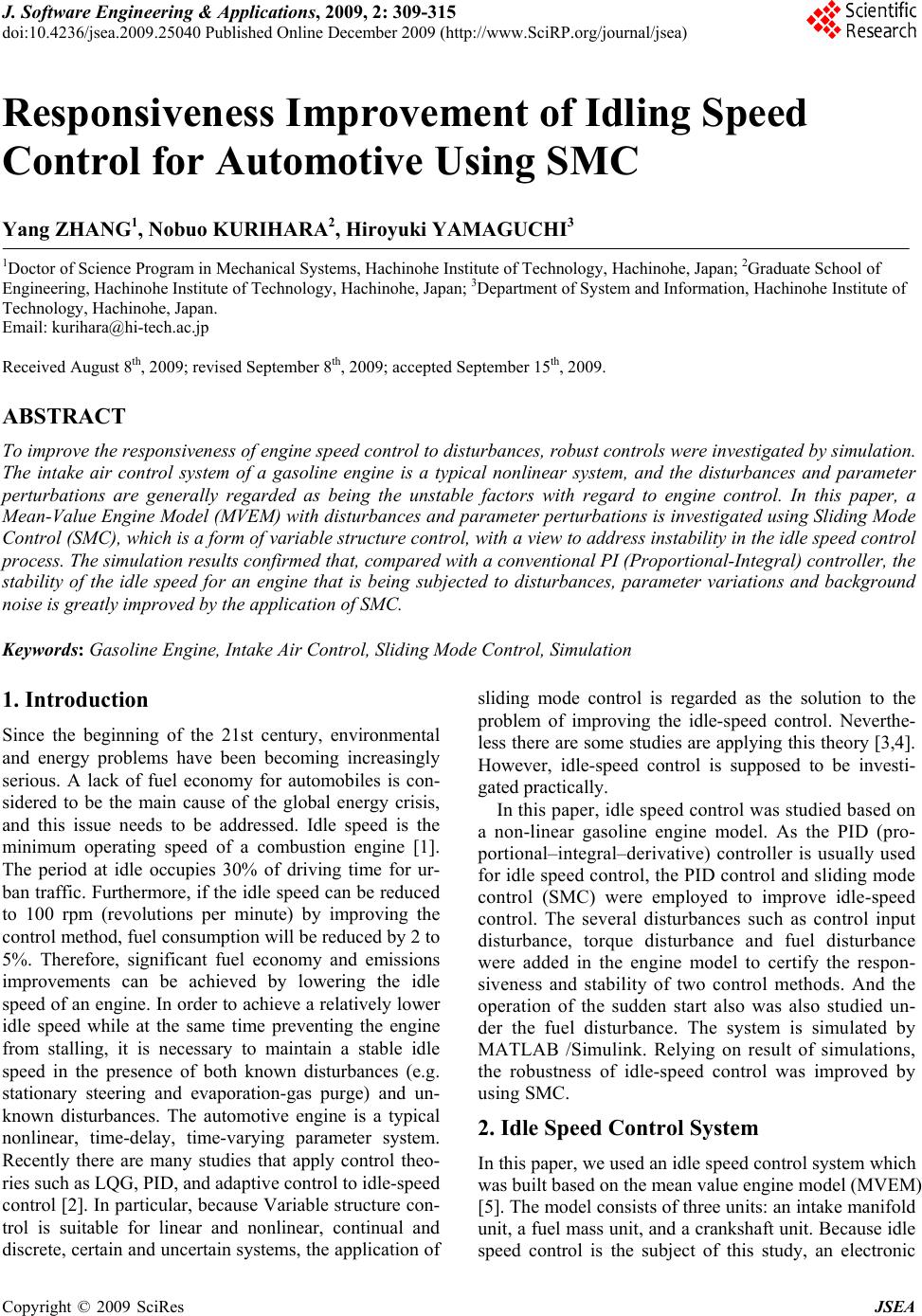 J. Software Engineering & Applications, 2009, 2: 309-315 doi:10.4236/jsea.2009.25040 Published Online December 2009 (http://www.SciRP.org/journal/jsea) Copyright © 2009 SciRes JSEA 309 Responsiveness Improvement of Idling Speed Control for Automotive Using SMC Yang ZHANG1, Nobuo KURIHARA2, Hiroyuki YAMAGUCHI3 1Doctor of Science Program in Mechanical Systems, Hachinohe Institute of Technology, Hachinohe, Japan; 2Graduate School of Engineering, Hachinohe Institute of Technology, Hachinohe, Japan; 3Department of System and Information, Hachinohe Institute of Technology, Hachinohe, Japan. Email: kurihara@hi-tech.ac.jp Received August 8th, 2009; revised September 8th, 2009; accepted September 15th, 2009. ABSTRACT To improve the responsiveness of engine speed control to disturbances, robust controls were investigated by simulation. The intake air control system of a gasoline engine is a typical nonlinear system, and the disturbances and parameter perturbations are generally regarded as being the unstable factors with regard to engine control. In this paper, a Mean-Value Engine Model (MVEM) with disturbances and parameter perturbations is investigated using Sliding Mode Control (SMC), which is a form of variable structure control, with a view to address instability in the idle speed control process. The simulation results confirmed that, compared with a conventional PI (Proportional-Integral) controller, the stability of the idle speed for an engine that is being subjected to disturbances, parameter variations and background noise is greatly improved by the application of SMC. Keywords: Gasoline Engine, Intake Air Control, Sliding Mode Control, Simulation 1. Introduction Since the beginning of the 21st century, environmental and energy problems have been becoming increasingly serious. A lack of fuel economy for automobiles is con- sidered to be the main cause of the global energy crisis, and this issue needs to be addressed. Idle speed is the minimum operating speed of a combustion engine [1]. The period at idle occupies 30% of driving time for ur- ban traffic. Furthermore, if the idle speed can be reduced to 100 rpm (revolutions per minute) by improving the control method, fuel consumption will be reduced by 2 to 5%. Therefore, significant fuel economy and emissions improvements can be achieved by lowering the idle speed of an engine. In order to achieve a relatively lower idle speed while at the same time preventing the engine from stalling, it is necessary to maintain a stable idle speed in the presence of both known disturbances (e.g. stationary steering and evaporation-gas purge) and un- known disturbances. The automotive engine is a typical nonlinear, time-delay, time-varying parameter system. Recently there are many studies that apply control theo- ries such as LQG, PID, and adaptive control to idle-speed control [2]. In particular, because Variable structure con- trol is suitable for linear and nonlinear, continual and discrete, certain and uncertain systems, the application of sliding mode control is regarded as the solution to the problem of improving the idle-speed control. Neverthe- less there are some studies are applying this theory [3,4]. However, idle-speed control is supposed to be investi- gated practically. In this paper, idle speed control was studied based on a non-linear gasoline engine model. As the PID (pro- portional–integral–derivative) controller is usually used for idle speed control, the PID control and sliding mode control (SMC) were employed to improve idle-speed control. The several disturbances such as control input disturbance, torque disturbance and fuel disturbance were added in the engine model to certify the respon- siveness and stability of two control methods. And the operation of the sudden start also was also studied un- der the fuel disturbance. The system is simulated by MATLAB /Simulink. Relying on result of simulations, the robustness of idle-speed control was improved by using SMC. 2. Idle Speed Control System In this paper, we used an idle speed control system which was built based on the mean value engine model (MVEM) [5]. The model consists of three units: an intake manifold unit, a fuel mass unit, and a crankshaft unit. Because idle speed control is the subject of this study, an electronic  Responsiveness Improvement of Idling Speed Control for Automotive Using SMC 310 Figure 1. Engine model for idle speed system throttle is necessary. The usual control process for idle speed is illustrated as follows. The intake air flow is ad- justed to achieve the set point for the engine speed by adjusting the angle and position of the electronic throttle. The crank angle sensor detects the engine speed, and the angle of the electronic throttle depends on the controller in the engine control unit. Next, the amount of air sup- plied to the cylinder is adjusted using the electronic throttle. Once that has been done, an amount of fuel pro- portionate to the air flow is injected into the cylinder. Thus, the torque produced by fuel combustion maintains a constant engine speed. A model of an idle speed control system is shown in Figure 1. Next, we will describe the three parts of the engine model by providing the equations we used. The main initial parameters of the engine model were as follows: the engine displacement (Vd) is 1.3 L; the fuel energy constant (Hu) was 43000 K J/kg; the gas constant of air (R) was 0.00287 m2bar/k.kg; the atmospheric tempera- ture (Ta) was 293 K; the intake manifold volume Vi was 0.000564 m3 the atmospheric pressure (Pa) was 1.013 bar; and the moment of engine inertia was 5.2638 kgm2. Here we considered four factors that can easily make idle speed control unstable: torque disturbance, fuel vapor disturbance, control input disturbance, and parameter errors. 2.1 Crankshaft Block ui ffpd n = HmInPPPIn (1) The variable n in Equation (1) is the engine speed (the unit used was set at rpm/1000); ηi is the thermal effi- ciency; and Pf , Pp and Pb are frictional power, pumping power, and load power, respectively. 036 0.392 n1 n inp = = 0.015+0.558 2 2 2 0.392 0.0171 1.740.745 0.00048 pii mbt mbt =0.827+0.528P P = =0.7+0.024 Pf , Pp and Pb are calculated using the three empirical equations below. 23 2 3 1 673 09 f P. P. PM 0 2720 0135 69 0206 260 pi i bb b n.n. n nP.nP n Kn (2) Here, Pi is the manifold pressure; θ is the ignition an- gle; θmbt is the mean best torque spark advance; λ is the excess air coefficient; and Mb and Kb are both for the torque load. 2.2 Fuel Block 2 1 0 2270 0550 68 1 350 06721 680 8250 060150 56 fffiff f fv fi i fi mXmm mXm X.P.n. ..n.P..n.. (3) Here, f f m is the evaporation fuel in the cylinder; is the injected fuel; is the gasified fuel; is the total amount of fuel in the cylinder; X is the coeffi- cient of the fuel deposit; and is the time constant for fuel evaporation. fi m fv m f m f 2.3 Manifold Block iiatapii ii PRTm mVPT/T (4) Here, is the temperature in the manifold; is the intake air which passes through the throttle; and is the cylinder intake air. i Tat m m ap atis ai mmm (5) where is the intake air that passes through the by-pass valve is m 12 0 39880 01 ai r m.uP. (6) Here, is the intake air that passes through the throttle. ai m 2 111 407318004087180u.cosu .cosu 2 2 04125 10 4125 104125 00 4125 r r r r P. P. P. P. (7) Copyright © 2009 SciRes JSEA  Responsiveness Improvement of Idling Speed Control for Automotive Using SMC311 Here, u is the opening of the throttle and r P ratio of to Wher is the i P e a P. v is the engine volumetric efficiency. 2 2 0075 4 vi i P TR m 095 0 14 a patiataiii .mT .mTTPV 3. Lineariz As is well known, the engine model is a typical n- inear system. For the following design for SMC, we needed to linearize the engine model to a state-space ion point. In this case, we selected .. ation no equation at the operat an engine speed of n and manifold pressure of i P as two states. Here, u is the input of advance angle igni- tion and u is the input of the throttle, and both were provisionally considered as control inputs. 1 2 110 i u xn xu P xu Ax Bx Ax Bx 2 2 2 1 21 2 12 0 018410 0390 31780 05160 0026 61 8951815 521 397 680 7 ii i np ap i Bx Ax xA x Bxu A x.P.nP. .n.n Ax.nP.. n Bxm.nB xRTV (8) Having sorted out the affine non-linear equations as stated above, we then addressed the target operation point (xd), which is given as follows: d d n xP id Therefore, the engine model is linearized in the vicin- ity of xd . (9) 111211 12 d 212221 22 d x xxuuux AxBu a AB a bb (10) aa bb Next, w e substituted the tangent line for the curved line according to the affine non-linear equation. 1 1 1 1 n n dd x, u nn 11 1 1 11 12 21 2 22 12 21 12 22 0 0390 05160 0052 0 18410 0039 0 0390 05160 0052 61 89518 0 680 7 1552 dd d n x,u nn n d d d d ix np ap ff uu f Buff uu a.. . a. .n a.. . a. n P bb bm.n b n n (11) As a result, we were able to obtain the final matrices for A and B of the linearized model at two certain values of the abovementioned states. 4. PID Control Design In the paper, we employed PI controller shown in Figure 2. Design ucture control in which the dynamic system to slide along the re- n important, ro- The gain of Kp and Ki are determined by the Ziegler- Nichols method. 5. Sliding Mode Control SMC is a type of variable str dynamics of a nonlinear system are altered by the appli- cation of a high-frequency switching control [6]. In other words, SMC uses practically infinite gain to force the trajectories of a stricted sliding mode subspace. This is a bust control approach that provides an adaptive approach to tackling the parametric system, uncertain parametric system, and uncertain disturbance system. If a switching surface is appropriately designed with desirable charac- teristics, the system will exhibit desirable behavior when confined to this switching surface. To pursue the target value, idle-speed control can be shown as a servo system. Thus, the sliding mode for a single-input single-output f f x x f Ax f f x x Figure 2. Block diagram of PI controller Copyright © 2009 SciRes JSEA  Responsiveness Improvement of Idling Speed Control for Automotive Using SMC 312 Figure 3. Block diagram of SMC system has been made into the block diagram shown in Figure 2, which illustrates a closed-loop SMC. The con- trol input is the sum of the linear and non-linear inputs. Here, nd is the target engine speed, n is the actual engine speed, and the four kinds of disturbances we have consid- ered in this paper have also been added in the Figure 3. 5.1 Controller In this paperngle of the rottle as the control input. Consequently, the following , we are only considering the a th system is considered. 1112 11 12 21 22 2222 12 11 12 21 2222 i xxb aa u aa xxb b naa u Paa b ly SMC to the servo system, an expan- (13) The expansion servo system is given below. (12) In order to app sion system is used in which a new state, z, is assumed as the value for the integration of the difference between the target value and input. The variable z is defined in Equa- tion (13) below. 1d zrx nn in Equation (14) 111121 21 2222 22 00 0 00 0100 1zz x aa xur aa b xx (14) Equation (14) can be rewritten as follows: x Ax Bu Er (15) The switching function is as follows: 1 2 z x Sx Sx x (16) The design for the switching surface is described late. When the system is in sliding mode, the switchin tion is as follows: g func- 0x (17) characteristic is exhibite hy When the system is in sliding mode state, the dynamic d. When above the switching per-plane, the system maintains 0 . Hence, by using xS, substituting Equation (15) into 0 gives: 0eq SAx SBur SE (18) Taking the control law as: 1 eq r uSBSAxSE (19) Equation (19) gives th servo system with sliding the switc s give where P is the positive definite soluti eq e equivalent linear control of a mode. 5.2 Hyper-Plane For the system stability margin, hing hyper- plane S in as follows: T SBP (20) on of the Riccati uations, so that: 0 TT PAA PPBBPQ AAI Where (21) is the stability margin coefficient, >0 is switching law, the Lyapunov func- assumed. To determine the tion candidate with is defined as follows: 2 1 2 Vx efinite function, (22) If the first-order derivative V of the Lyapunov func- tion is a negative d can converge to 0. So the control input is the sum of the linear and non-linear inputs. (23) nl eq nl Here, non-linear input u is obtained as follows: uu u 1 nl uk SB (24) If >0, k >0 en , k is the non and it is efficit in compensating for unknown distur- ba -linear input switching gain nces. To alleviate chatter in the control output of the sliding mode controller, we used as the output alteration, which is generally called the smooth function Copyright © 2009 SciRes JSEA 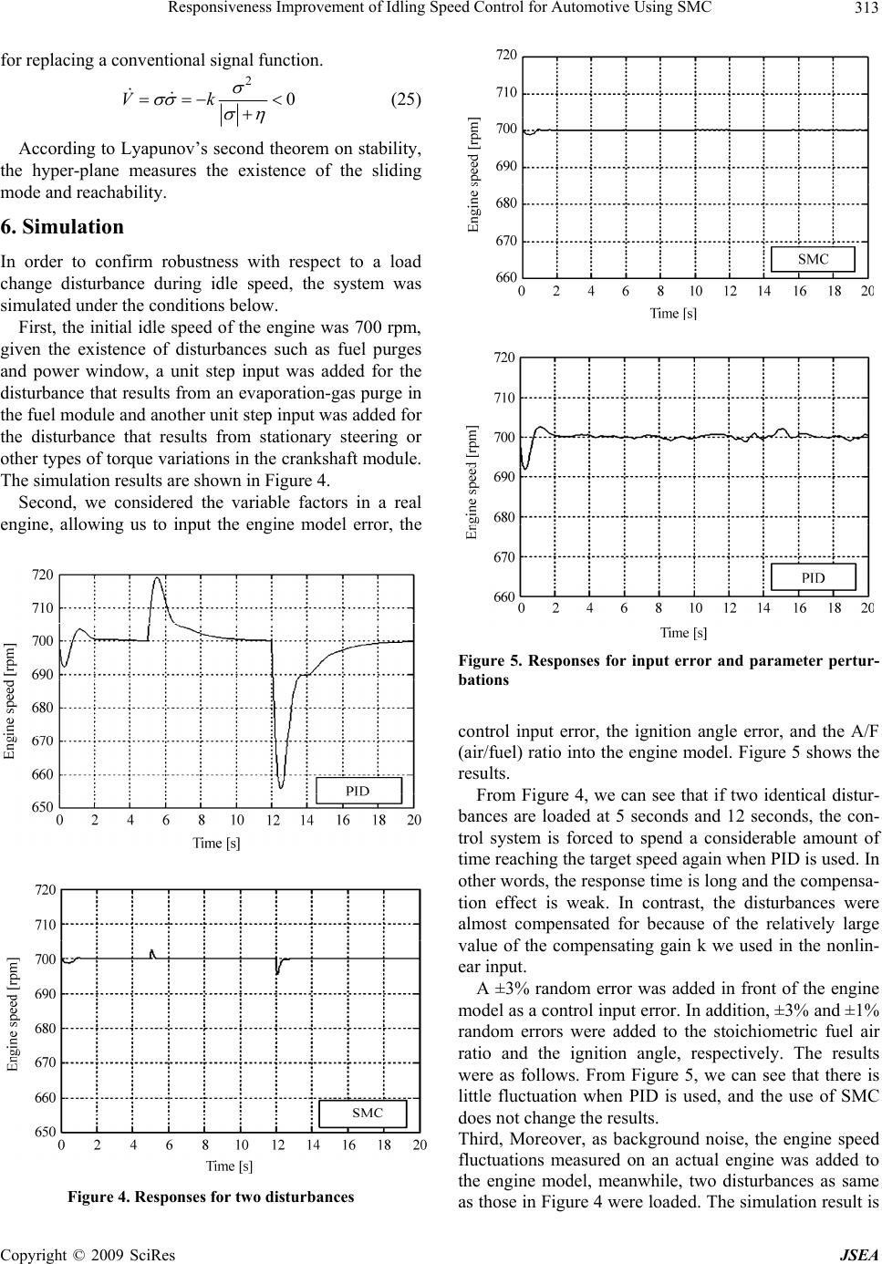 Responsiveness Improvement of Idling Speed Control for Automotive Using SMC313 for replacing a conventional signal function. 2 0Vk (25) According to Lyapunov’s second theo the hyper-plane measures the existence of the sliding m a th resp d, th fuel purges and power window, a unit step input w disturbance that results from an evaporation-gas purge in th e shown in Figure 4. sidered the variable factors in a real rem on stability, odend reachability. 6. Simulation In order to confirm robustness wiect to a load change disturbance during idle speee system was simulated under the conditions below. First, the initial idle speed of the engine was 700 rpm, given the existence of disturbances such as as added for the e fuel module and another unit step input was added for the disturbance that results from stationary steering or other types of torque variations in the crankshaft module. The simulation results ar Second, we con engine, allowing us to input the engine model error, the F bations igure 5. Responses for input error and parameter pertur- control input error, the ignition angle error, and the A/F (air/fuel) ratio into the engine model. Figure 5 shows the results. From Figure 4, we can see that if two identical distur- bances are loaded at 5 seconds and 12 seconds, the con- trol system is forced to spend a considerable amount of time reaching the target speed again when PID is used. In other words, the response time is long and the compensa- tion effect is weak. In contrast, the disturbances were almost compensated for because of the relatively large value of the compensating gain k we used in the nonlin ear input. s a control input error. In addition, ±3% and ±1% ndom errors were added to the stoichiometric fuel air ctuation when PID is used, and the use of SMC do as those in Figure 4 were loaded. The simulation result is - A ±3% random error was added in front of the engine model a ra ratio and the ignition angle, respectively. The results were as follows. From Figure 5, we can see that there is little flu es not change the results. Third, Moreover, as background noise, the engine speed fluctuations measured on an actual engine was added to the engine model, meanwhile, two disturbances as same Figure 4. Responses for two disturbances Copyright © 2009 SciRes JSEA  Responsiveness Improvement of Idling Speed Control for Automotive Using SMC 314 shown in Figure 6. The control system with the sliding mode controller is clearly more effective against both of the two disturbances as if background noise was loaded. Finally, we considered the responsiveness and tracing ability when the engine is made a sudden start from a lo ulation results are shown in gi wer idle speed to a higher speed such as 2000rpm. As far as we know, there is usually little fuel loss in the sudden start condition due to some of fuel drops attached to the manifold, which sometimes leads to the undesir- able speed down. So we assumed the sudden start oc- curred at 6 seconds and a step disturbance as fuel loss was load at the time. The sim Figure 7. Apparently, the transition of the sudden start by SMC is faster than that by PI although the disturbance is loaded. Based on the aforementioned simulation results, we can see that a control system with a sliding mode con- troller is more effective with respect to either of the two disturbances, as well as to some errors in the actual en- ne, proving the robustness of SMC. In addition, the tracing ability of idle speed also appears to be improved Figure 7. Responses for a sudden start from 700 rpm in the work condition under the sudden start with the fue isturbance. 7. Conclusions In this paper we addressed the issue of idle speed control in order to improve the stability of an engine’s idle speed and improve its fuel economy. To achieve high stability and robustness for the idle speed control system, the electronic throttle (which regulates the intake air flow when an engine is idling) was taken as the control object, the engine was modularized by MATLAB/SIMULINK, and given that the engine system is a typical nonlinear system, the model was linearized at the operating point. Using a linearized state-space model, we built a hy perter hich we also designed a control input for a controlled lts, PI control was used, and in accordance ls, the parameters of proportion and l d - -plane which is adaptive to the controlled plant, af w plant which is the sum of the nonlinear and linear inputs, so the SMC is constructed in m-file. To produce com- parative resu with Ziegler-Nicho integral were adjusted on the initial engine speed of 700 rpm. By using SMC, the switching hyper-plane was de- signed based on system zeros, and the system was de- signed as a servo system in order to achieve the target value. Compared with conventional PI control, the stabil- ity against disturbances was improved. Furthermore, the Figure 6. Responses for loading engine-speed signal Copyright © 2009 SciRes JSEA 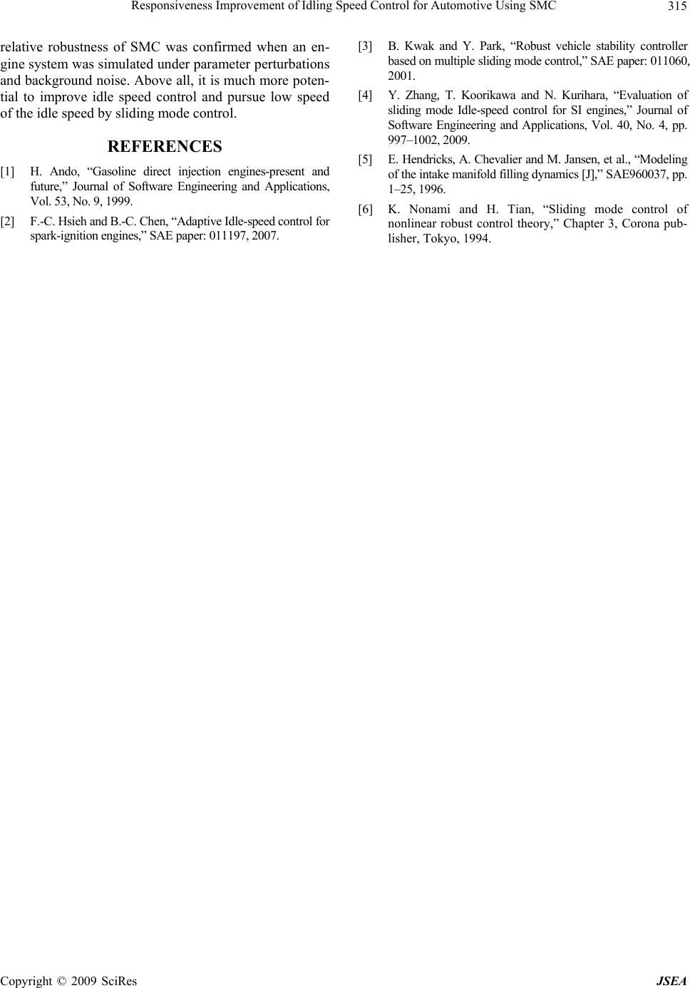 Responsiveness Improvement of Idling Speed Control for Automotive Using SMC Copyright © 2009 SciRes JSEA 315 [3] B. Kwak and stability controller 996. relative robustness of SMC was confirmed when an en- gine system was simulated under parameter perturbations and background noise. Above all, it is much more poten- tial to improve idle speed control and pursue low speed of the idle speed by sliding mode control. REFERENCES [1] H. Ando, “Gasoline direct injection engines-present and future,” Journal of Software Engineering and Applications, Vol. 53, No. 9, 1999. [2] F.-C. Hsieh and B.-C. Chen, “Adaptive Idle-speed control for spark-ignition engines,” SAE paper: 011197, 2007. Y. Park, “Robust vehicle based on multiple sliding mode control,” SAE paper: 011060, 2001. [4] Y. Zhang, T. Koorikawa and N. Kurihara, “Evaluation of sliding mode Idle-speed control for SI engines,” Journal of Software Engineering and Applications, Vol. 40, No. 4, pp. 997–1002, 2009. [5] E. Hendricks, A. Chevalier and M. Jansen, et al., “Modeling of the intake manifold filling dynamics [J],” SAE960037, pp. 1–25, 1 [6] K. Nonami and H. Tian, “Sliding mode control of nonlinear robust control theory,” Chapter 3, Corona pub- lisher, Tokyo, 1994. |