Paper Menu >>
Journal Menu >>
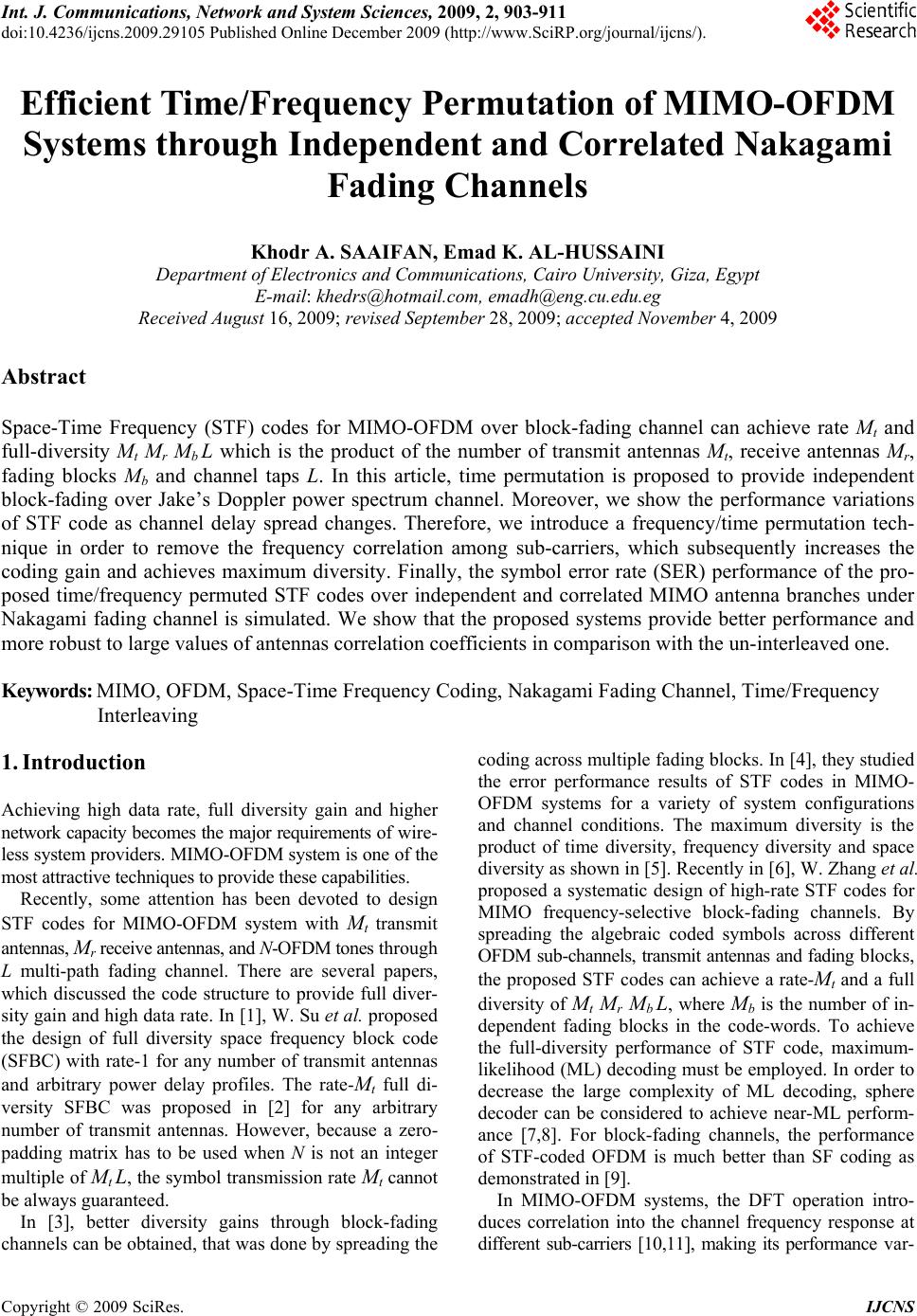 Int. J. Communications, Network and System Sciences, 2009, 2, 903-911 doi:10.4236/ijcns.2009.29105 Published Online December 2009 (http://www.SciRP.org/journal/ijcns/). Copyright © 2009 SciRes. IJCNS 903 Efficient Time/Frequency Permutation of MIMO-OFDM Systems through Independent and Correlated Nakagami Fading Channels Khodr A. SAAIFAN, Emad K. AL-HUSSAINI Department of Electronics and Communications, Cairo University, Giza, Egypt E-mail: khedrs@hotmail.com, emadh@eng.cu.edu.eg Received August 16, 2009; revised September 28, 2009; accepted November 4, 2009 Abstract Space-Time Frequency (STF) codes for MIMO-OFDM over block-fading channel can achieve rate Mt and full-diversity Mt Mr Mb L which is the product of the number of transmit antennas Mt, receive antennas Mr, fading blocks Mb and channel taps L. In this article, time permutation is proposed to provide independent block-fading over Jake’s Doppler power spectrum channel. Moreover, we show the performance variations of STF code as channel delay spread changes. Therefore, we introduce a frequency/time permutation tech- nique in order to remove the frequency correlation among sub-carriers, which subsequently increases the coding gain and achieves maximum diversity. Finally, the symbol error rate (SER) performance of the pro- posed time/frequency permuted STF codes over independent and correlated MIMO antenna branches under Nakagami fading channel is simulated. We show that the proposed systems provide better performance and more robust to large values of antennas correlation coefficients in comparison with the un-interleaved one. Keywords: MIMO, OFDM, Space-Time Frequency Coding, Nakagami Fading Channel, Time/Frequency Interleaving 1. Introduction Achieving high data rate, full diversity gain and higher network capacity becomes the major requirements of wire- less system providers. MIMO-OFDM system is one of the most attractive techniques to provide these capabilities. Recently, some attention has been devoted to design STF codes for MIMO-OFDM system with Mt transmit antennas, Mr receive antennas, and N-OFDM tones through L multi-path fading channel. There are several papers, which discussed the code structure to provide full diver- sity gain and high data rate. In [1], W. Su et al. proposed the design of full diversity space frequency block code (SFBC) with rate-1 for any number of transmit antennas and arbitrary power delay profiles. The rate-Mt full di- versity SFBC was proposed in [2] for any arbitrary number of transmit antennas. However, because a zero- padding matrix has to be used when N is not an integer multiple of Mt L, the symbol transmission rate Mt cannot be always guaranteed. In [3], better diversity gains through block-fading channels can be obtained, that was done by spreading the coding across multiple fading blocks. In [4], they studied the error performance results of STF codes in MIMO- OFDM systems for a variety of system configurations and channel conditions. The maximum diversity is the product of time diversity, frequency diversity and space diversity as shown in [5]. Recently in [6], W. Zhang et al. proposed a systematic design of high-rate STF codes for MIMO frequency-selective block-fading channels. By spreading the algebraic coded symbols across different OFDM sub-channels, transmit antennas and fading blocks, the proposed STF codes can achieve a rate-Mt and a full diversity of Mt Mr Mb L, where Mb is the number of in- dependent fading blocks in the code-words. To achieve the full-diversity performance of STF code, maximum- likelihood (ML) decoding must be employed. In order to decrease the large complexity of ML decoding, sphere decoder can be considered to achieve near-ML perform- ance [7,8]. For block-fading channels, the performance of STF-coded OFDM is much better than SF coding as demonstrated in [9]. In MIMO-OFDM systems, the DFT operation intro- duces correlation into the channel frequency response at different sub-carriers [10,11], making its performance var- 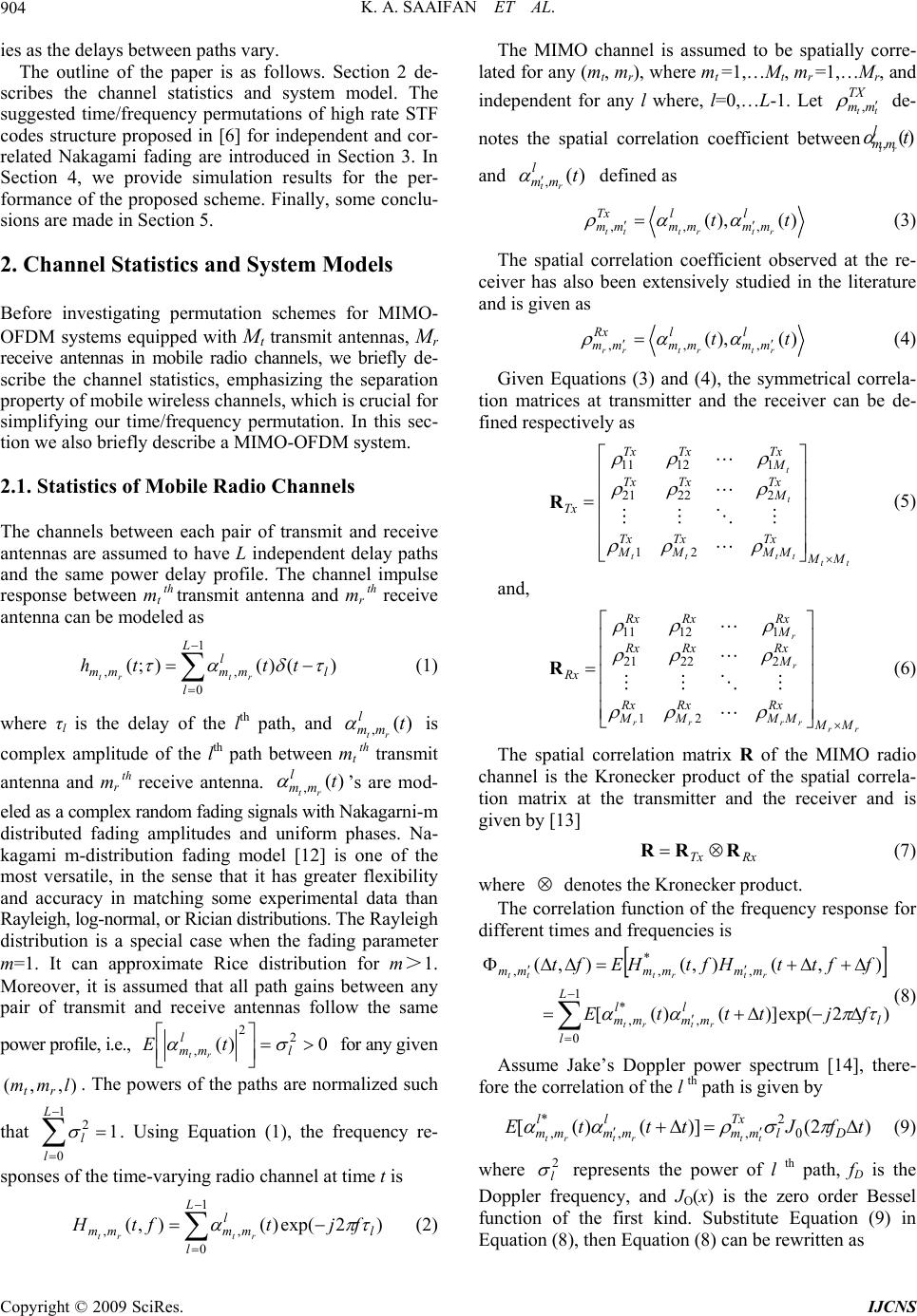 K. A. SAAIFAN ET AL. 904 ies as the delays between paths vary. The outline of the paper is as follows. Section 2 de- scribes the channel statistics and system model. The suggested time/frequency permutations of high rate STF codes structure proposed in [6] for independent and cor- related Nakagami fading are introduced in Section 3. In Section 4, we provide simulation results for the per- formance of the proposed scheme. Finally, some conclu- sions are made in Section 5. 2. Channel Statistics and System Models Before investigating permutation schemes for MIMO- OFDM systems equipped with Mt transmit antennas, Mr receive antennas in mobile radio channels, we briefly de- scribe the channel statistics, emphasizing the separation property of mobile wireless channels, which is crucial for simplifying our time/frequency permutation. In this sec- tion we also briefly describe a MIMO-OFDM system. 2.1. Statistics of Mobile Radio Channels The channels between each pair of transmit and receive antennas are assumed to have L independent delay paths and the same power delay profile. The channel impulse response between mt th transmit antenna and mr th receive antenna can be modeled as 1 0 ,, )()();( L l l l mmmm ttth rtrt (1) where τl is the delay of the lth path, and is complex amplitude of the lth path between mt th transmit antenna and mr th receive antenna. ’s are mod- eled as a complex random fading signals with Nakagarni-m distributed fading amplitudes and uniform phases. Na- kagami m-distribution fading model [12] is one of the most versatile, in the sense that it has greater flexibility and accuracy in matching some experimental data than Rayleigh, log-normal, or Rician distributions. The Rayleigh distribution is a special case when the fading parameter m=1. It can approximate Rice distribution for m>1. Moreover, it is assumed that all path gains between any pair of transmit and receive antennas follow the same power profile, i.e., )( ,t l mm rt )( ,t l mm rt 0 2 l )( 2 , l mm tErt for any given . The powers of the paths are normalized such that . Using Equation (1), the frequency re- sponses of the time-varying radio channel at time t is ),,( lmm rt 1 0 2 L l l 1 )2exp()(),( 1 0 ,, l L l l mmmm fjtftH rtrt (2) The MIMO channel is assumed to be spatially corre- lated for any (mt, mr), where mt =1,…Mt, mr =1,…Mr, and independent for any l where, l=0,…L-1. Let de- notes the spatial correlation coefficient between and defined as TX mm tt , , l m t )(t m r )( ,t l mmrt )(),( ,,, tt l mm l mm Tx mmrtrttt (3) The spatial correlation coefficient observed at the re- ceiver has also been extensively studied in the literature and is given as )(),( ,,, tt l mm l mm Rx mm rtrtrr (4) Given Equations (3) and (4), the symmetrical correla- tion matrices at transmitter and the receiver can be de- fined respectively as tt tttt t t MM Tx MM Tx M Tx M Tx M TxTx Tx M TxTx Tx 21 22221 11211 R (5) and, rr rrrr r r MM Rx MM Rx M Rx M Rx M RxRx Rx M RxRx Rx 21 22221 11211 R (6) The spatial correlation matrix R of the MIMO radio channel is the Kronecker product of the spatial correla- tion matrix at the transmitter and the receiver and is given by [13] RxTx RRR (7) where denotes the Kronecker product. The correlation function of the frequency response for different times and frequencies is 1 0 , * , , * ,, )2exp()]()([ ),(),(),( L l l l mm l mm mmmmmm fjtttE ffttHftHEft rtrt rtrttt (8) Assume Jake’s Doppler power spectrum [14], there- fore the correlation of the l th path is given by )2()]()([ 0 2 ,, * ,tfJtttE Dl Tx mm l mm l mm ttrtrt (9) where represents the power of l th path, fD is the Doppler frequency, and JO(x) is the zero order Bessel function of the first kind. Substitute Equation (9) in Equation (8), then Equation (8) can be rewritten as 2 l Copyright © 2009 SciRes. IJCNS 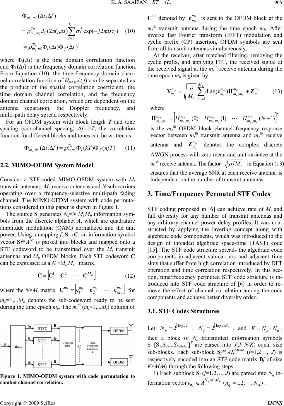 K. A. SAAIFAN ET AL. 905 )()( )2exp()2( ),( , 1 0 2 0, , ft fjtfJ ft ft Tx mm L l llD Tx mm mm tt tt tt (10) where Φt(Δt) is the time domain correlation function and Φf (Δf) is the frequency domain correlation function. From Equation (10), the time-frequency domain chan- nel correlation function of Hmt,mr(t,f) can be separated as the product of the spatial correlation coefficient, the time domain channel correlation, and the frequency domain channel correlation, which are dependent on the antenna separation, the Doppler frequency, and multi-path delay spread respectively. For an OFDM system with block length T and tone spacing (sub-channel spacing) Δf=1/T, the correlation function for different blocks and tones can be written as )()(),( ,TnkTftft Tx mmmm tttt (11) 2.2. MIMO-OFDM System Model Consider a STF-coded MIMO-OFDM system with Mt transmit antennas, Mr receive antennas and N sub-carriers operating over a frequency-selective multi-path fading channel. The MIMO-OFDM system with code permuta- tions considered in this paper is shown in Figure 1. The source S generates Ns=N Mt Mb information sym- bols from the discrete alphabet A, which are quadrature amplitude modulation (QAM) normalized into the unit power. Using a mapping f: S→C, an information symbol vector S∈ANs is parsed into blocks and mapped onto a STF codeword to be transmitted over the Mt transmit antennas and Mb OFDM blocks. Each STF codeword C can be expressed as a N ×Mb Mt matrix. b M CCCC 21 (12) where the N×Mt matrix b t bb bm M mm mcccC 21 for mb=1,...Mb denotes the sub-codeword ready to be sent during the time epoch mb. The mt th (mt=1,...Mt) column of Figure 1. MIMO-OFDM system with code permutation to combat channel correlation. Cmb denoted by is sent to the OFDM block at the mt th transmit antenna during the time epoch mb. After inverse fast Fourier transform (IFFT) modulation and cyclic prefix (CP) insertion, OFDM symbols are sent from all transmit antennas simultaneously. b t m m c At the receiver, after matched filtering, removing the cyclic prefix, and applying FFT, the received signal at the received signal at the mr th receive antenna during the time epoch mb is given by b r t t b rt b t b r m m M m m mm m m t m mMZHcY 1 , )(diag (13) where T m mm m mm m mm m mm NHHH b rt b rt b rt b rt )1()1()0(,,,, H b t m m Z is the mb th OFDM block channel frequency response vector between mt th transmit antenna and mr th receive antenna and denotes the complex discrete AWGN process with zero mean and unit variance at the mr th receive antenna. The factor t M in Equation (13) ensures that the average SNR at each receive antenna is independent on the number of transmit antennas. 3. Time/Frequency Permuted STF Codes STF coding proposed in [6] can achieve rate of Mt and full diversity for any number of transmit antennas and any arbitrary channel power delay profiles. It was con- structed by applying the layering concept along with algebraic code components, which was introduced in the design of threaded algebraic space-time (TAST) code [15]. The STF code structure spreads the algebraic code components in adjacent sub-carriers and adjacent time slots that suffer from high correlation introduced by DFT operation and time correlation respectively. In this sec- tion, time/frequency permuted STF code structure is in- troduced into STF code structure of [6] in order to re- move the effect of channel correlation among the code components and achieve better diversity order. 3.1. STF Codes Structures Let , , and , then a block of Ns transmitted information symbols S=[S1,S2,...SNMtMb]T are parsed into J(J=N/K) equal size sub-blocks. Each sub-block Sj∈AKMtMb (j=1,2…, J) is respectively encoded into an STF code matrix Bj of size K×MtMb through the following steps: L p N2 log 2 t M q N2 log 2 qp NNK 1) Each subblock Sj (j=1,2…, J) are parsed into Nq in- formation vector. btp q MMN nAs),,2,1( qq Nn Copyright © 2009 SciRes. IJCNS 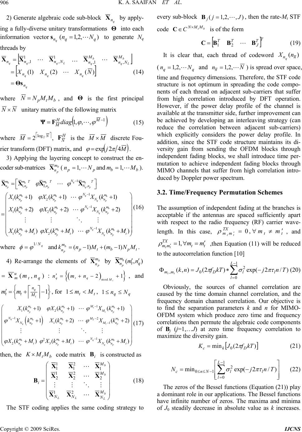 K. A. SAAIFAN ET AL. 906 2) Generate algebraic code sub-block q n X by apply- ing a fully-diverse unitary transformations into each information vector to generate Nq threads by Θ ),2,1( qqn Nn q s q qqq b Lq b q Lqqq n nnn M Nn M n Nnnn NXXX Θs XXXXX )()2()1( ,1, 1 , 1 1, (14) where btp MMNN , and is the first principal Θ NN unitary matrix of the following matrix 1 ,,,1 MH Mdiag FΨ (15) where N M 2 log 2, H N F is the M M discrete Fou- rier transform (DFT) matrix, and Mj 42exp . 3) Applying the layering concept to construct the en- coder sub-matrices b p m n X(and ). pp Nn,1bbMm,1 1 1, 2,, 1 12 1 12 1 12 (1) (1)(1) (2) (2)(2) ()() () q bb bb pp pqp q bb b pp qp q bb b pp qp q bb b pp qp N mm mm TT T nn nNn N mm m nn Nn N mm m nn Nn N mm m nt ntNnt XkXkX k XkXkX k Xk MXkMXk M XX XX ( where and 4) Re-arrange the elements of 16) q N/1 tpbtp m nMNmMnk b p)1()1( . b p m n X by ),(qt m nnm b p X ),( qt u mnmX: mod 21 t qtq M nmn , and 1 t q M n tt mm , for tt Mm 1, qNn 1q 1 12 12 1 1 2 23 (1) (1)(1) 1(2) (2 ()() () bbtb pp tp qbb b T qppt p q bb b pp qp mmMm nn Mn Nmm m M NnnM n N mm m nt ntNnt XkXkX k XkXkX k Xk MXk MXk M 1 ) (17) then, the code matrix is constructed as bt MMK i B b M X 21 b L LL b M N NN M i XXX XXX XX B 21 2 2 2 1 2 1 11 (18) The STF coding applies the same coding strategy to every sub-block ),,2,1( Jj jB, then the rate-Mt STF code tMMN C Cb is of the form T T J BBBC 21 TT (19) It is clear that, each thread of codeword )(nX nnq (qq Nn ,2,1 and Nnn,2,1) is spread ove tiency dimerefore, the STF code structure is not optimum in spreading the code compo- nents of each thread on adjacent sub-carriers that suffer from high correlation introduced by DFT operation. However, if the power delay profile of the channel is available at the transmitter side, further improvement can be achieved by developing an interleaving strategy (can reduce the correlation between adjacent sub-carriers) which explicitly considers the power delay profile. In addition, since the STF code structure maintains its di- versity gain from sending the OFDM blocks through independent fading blocks, we shall introduce time per- mutation to achieve independent fading blocks through MIMO channels that suffer from high correlation intro- duced by Doppler power spectrum. r space, me and frequensions. Th 3.2. Time/Frequency Permutation Schemes he assumption of independent fading at the branches is to the autocorrelatio (20) Obviously, the sources of channel correlation are ca T acceptable if the antennas are spaced sufficiently apart with respect to the radio frequency (RF) carrier wave- length. In this case, tt TX mm mm t ,0 , and TX ,theuced n function [10] 1L t n Equation (11) will be red ttmm mm tt ,1 )/2exp()2(),( 0 2 0, TnjkTfJnk l l lDmm tt used by the time domain channel correlation, and the frequency domain channel correlation. Our objective is to find the separation parameters k and n for MIMO- OFDM system which produce zero time and frequency correlations then permute the algebraic code components of Bj (j=1,…J) at zero time frequency correlation to maximize the diversity gain. )2( 0kTfDkc minJK (21) (22) The zeros of the Bessel functions (Equation (21)) play a )/2exp(min 1 0 2 10 TnjN l L l lNnc dominant role in our applications. The Bessel functions have infinite number of zeros. The maxima and minima of J0 steadily decrease in absolute value as k increases. Copyright © 2009 SciRes. IJCNS 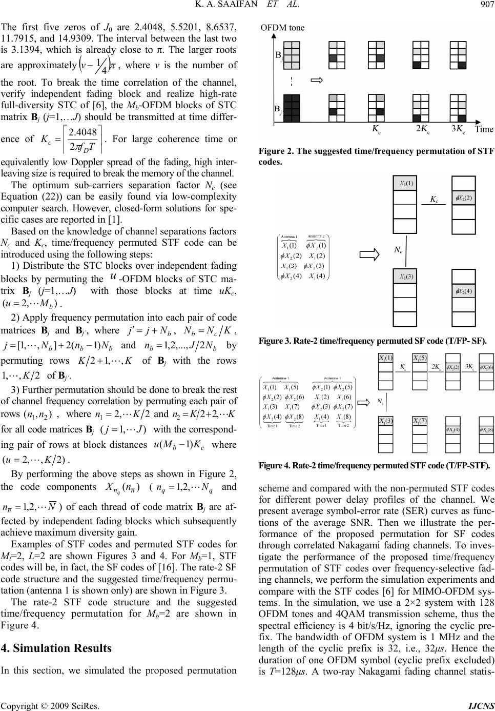 K. A. SAAIFAN ET AL. 907 The first five zeros of J0 are 2.4048, 5.5201, 8.6537, 11.7915, and 14.9309. The interval between the last two is 3.1394, which is already close to π. The larger roots are approximately 4 1 v, where v is the number of the root. To break correlation of the channel, verify independent fading block and realize high-rate full-diversity STC of [6], the Mb-OFDM blocks of STC matrix Bj (j=1,…J) should be transmitted at time differ- the time ence of 4048.2 leaving size is required to break the memory of the channel. The optimum sub-carriers separation factor Nc (see Tf K D c 2. For large coherence time or equivalently low Doppler spread of the fading, high inter- Eq annel separations factors N independent fading bl 2) Apply fruency permutation into each pair of code m uation (22)) can be easily found via low-complexity computer search. However, closed-form solutions for spe- cific cases are reported in [1]. Based on the knowledge of ch c and Kc, time/frequency permuted STF code can be introduced using the following steps: 1) Distribute the STC blocks over ocks by permuting the u-OFDM blocks of STC ma- trix Bj (j=1,…J) withhose blocks at time uKc, ),2( b Mu . eq t atrices Bj and Bj’, where b Njj , KNNcb , bbb NnNj)1(2],,1[ and bb n,1NJ 2.., b ,.2 y permuting rows K, oows K,12 f Bj with the r 2,,1K of Bj’. her perm3) Furtutation should be done to break the rest of channel frequency correlation by permuting each pair of rows ),( 21 nn , where2,2 1Kn and KKn ,22 2 for alatrices Bjwith ing pair of rows at bloccb KMu )1( where l code m the correspond- ),1( Jj k distances )2,,2( Ku . By performing the abgure 2, th ove steps as shown in Fi e code components )(nn nX q (qq Nn ,2,1 and Nnn,2,1) of each t pendent fading blocks which subsequently achieve maximum diversity gain. Examples of STF codes and pe hread of code m are af- fected by inde rmuted STF codes for M d tim 4. Simulation Results In this section, we simulated the proposed permutation atrix Bj t=2, L=2 are shown Figures 3 and 4. For Mb=1, STF codes will be, in fact, the SF codes of [16]. The rate-2 SF code structure and the suggested time/frequency permu- tation (antenna 1 is shown only) are shown in Figure 3. The rate-2 STF code structure and the suggeste e/frequency permutation for Mb=2 are shown in Figure 4. Figure 2. The suggested time/frequency permutation of STF codes. Figure 3. Rate-2 time/frequency permuted SF code (T/FP- S F). Figure 4. Rate-2 time/frequency permuted STF code (T/FP-STF). cheme and compared with the non-permuted STF codes s for different power delay profiles of the channel. We present average symbol-error rate (SER) curves as func- tions of the average SNR. Then we illustrate the per- formance of the proposed permutation for SF codes through correlated Nakagami fading channels. To inves- tigate the performance of the proposed time/frequency permutation of STF codes over frequency-selective fad- ing channels, we perform the simulation experiments and compare with the STF codes [6] for MIMO-OFDM sys- tems. In the simulation, we use a 2×2 system with 128 OFDM tones and 4QAM transmission scheme, thus the spectral efficiency is 4 bit/s/Hz, ignoring the cyclic pre- fix. The bandwidth of OFDM system is 1 MHz and the length of the cyclic prefix is 32, i.e., 32μs. Hence the duration of one OFDM symbol (cyclic prefix excluded) is T=128μs. A two-ray Nakagami fading channel statis- Copyright © 2009 SciRes. IJCNS 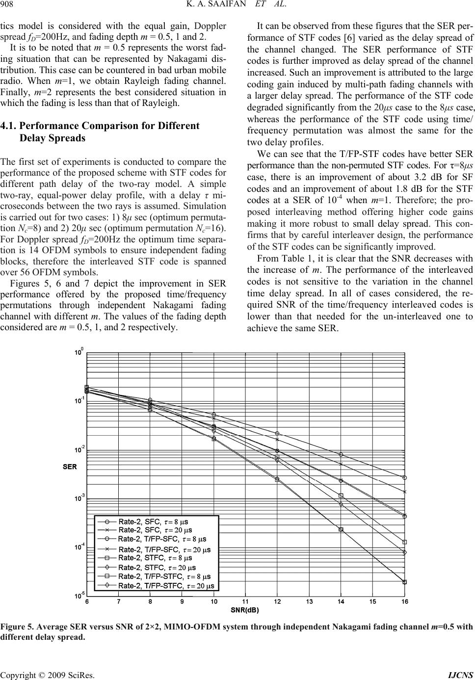 K. A. SAAIFAN ET AL. Copyright © 2009 SciRes. IJCNS 908 d- in .1. Performance Comparison for Different he first set of experiments is conducted to compare the pict the improvement in SER pe tics model is considered with the equal gain, Doppler spread fD=200Hz, and fading depth m = 0.5, 1 and 2. It is to be noted that m = 0.5 represents the worst fa It can be observed from these figures that the SER per- formance of STF codes [6] varied as the delay spread of the channel changed. The SER performance of STF codes is further improved as delay spread of the channel increased. Such an improvement is attributed to the large coding gain induced by multi-path fading channels with a larger delay spread. The performance of the STF code degraded significantly from the 20μs case to the 8μs case, whereas the performance of the STF code using time/ frequency permutation was almost the same for the two delay profiles. g situation that can be represented by Nakagami dis- tribution. This case can be countered in bad urban mobile radio. When m=1, we obtain Rayleigh fading channel. Finally, m=2 represents the best considered situation in which the fading is less than that of Rayleigh. 4 Delay Spreads We can see that the T/FP-STF codes have better SER performance than the non-permuted STF codes. For τ=8μs case, there is an improvement of about 3.2 dB for SF codes and an improvement of about 1.8 dB for the STF codes at a SER of 10-4 when m=1. Therefore; the pro- posed interleaving method offering higher code gains making it more robust to small delay spread. This con- firms that by careful interleaver design, the performance of the STF codes can be significantly improved. T performance of the proposed scheme with STF codes for different path delay of the two-ray model. A simple two-ray, equal-power delay profile, with a delay τ mi- croseconds between the two rays is assumed. Simulation is carried out for two cases: 1) 8μ sec (optimum permuta- tion Nc=8) and 2) 20μ sec (optimum permutation Nc=16). For Doppler spread fD=200Hz the optimum time separa- tion is 14 OFDM symbols to ensure independent fading blocks, therefore the interleaved STF code is spanned over 56 OFDM symbols. Figures 5, 6 and 7 de From Table 1, it is clear that the SNR decreases with the increase of m. The performance of the interleaved codes is not sensitive to the variation in the channel time delay spread. In all of cases considered, the re- quired SNR of the time/frequency interleaved codes is lower than that needed for the un-interleaved one to achieve the same SER. rformance offered by the proposed time/frequency permutations through independent Nakagami fading channel with different m. The values of the fading depth considered are m = 0.5, 1, and 2 respectively. Figure 5. Average SER versus SNR of 2×2, MIMO-OFDM system through independent Nakagami fading channel m=0.5 with different delay spread. 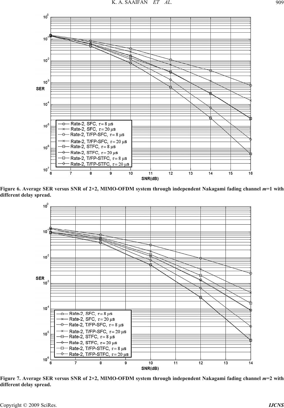 K. A. SAAIFAN ET AL. 909 Figure 6. Average SER versus SNR of 2×2, MIMO-OFDM system through independent Nakagami fading channel m=1 with different delay spread. Figure 7. Average SER versus SNR of 2×2, MIMO-OFDM system through independent Nakagami fading channel m=2 with different delay spread. Copyright © 2009 SciRes. IJCNS 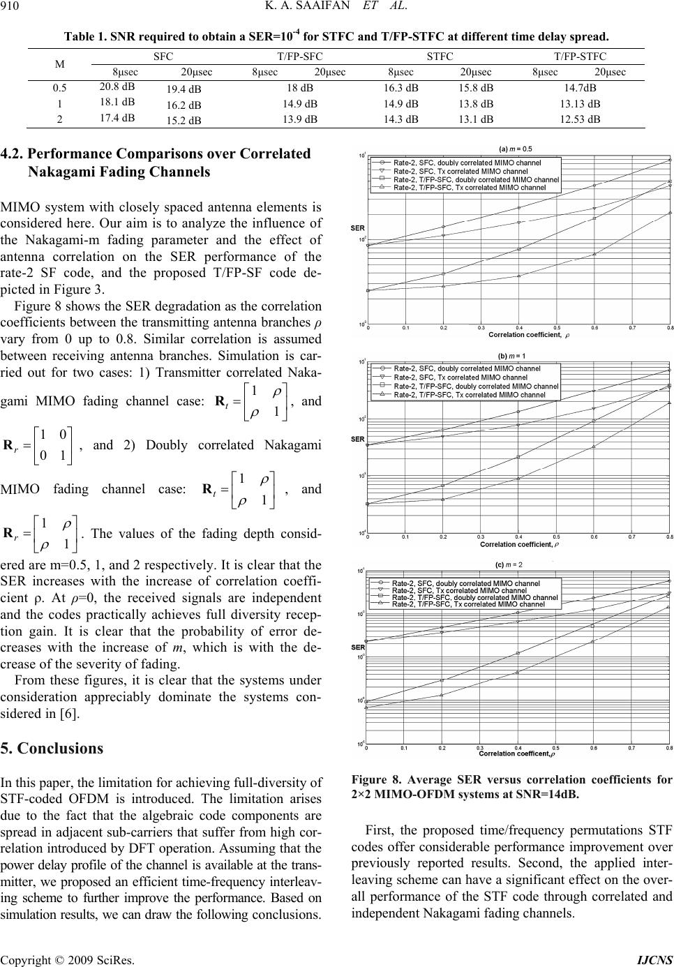 K. A. SAAIFAN ET AL. Copyright © 2009 SciRes. IJCNS 910 Table 1. SNR required to obtain a SER=10-4 for STFC and T/FP-STFC at different time delay spread. SFC T/FP-SFC STFC T/FP-STFC M 8μsec 20μsec 8μsec 20μsec 8μsec 20μsec 8μsec 20μsec 0.5 20.8 dB 19.4 dB 18 dB 16.3 dB 15.8 dB 14.7dB 1 18.1 dB 16.2 dB 14.9 dB 14.9 dB 13.8 dB 13.13 dB 2 17.4 dB 15.2 dB 13.9 dB 14.3 dB 13.1 dB 12.53 dB 4.2. Performance Comparisons over Correlated Nakagami Fading Channels MIMO system with closely spaced antenna elements is considered here. Our aim is to analyze the influence of the Nakagami-m fading parameter and the effect of antenna correlation on the SER performance of the rate-2 SF code, and the proposed T/FP-SF code de- picted in Figure 3. Figure 8 shows the SER degradation as the correlation coefficients between the transmitting antenna branches ρ vary from 0 up to 0.8. Similar correlation is assumed between receiving antenna branches. Simulation is car- ried out for two cases: 1) Transmitter correlated Naka- gami MIMO fading channel case: , and , and 2) Doubly correlated Nakagami MIMO fading channel case: , and . The values of the fading depth consid- ered are m=0.5, 1, and 2 respectively. It is clear that the SER increases with the increase of correlation coeffi- cient ρ. At ρ=0, the received signals are independent and the codes practically achieves full diversity recep- tion gain. It is clear that the probability of error de- creases with the increase of m, which is with the de- crease of the severity of fading. 1 1 t R 1 1 t 10 01 r R 1 1 r R R From these figures, it is clear that the systems under consideration appreciably dominate the systems con- sidered in [6]. 5. Conclusions Figure 8. Average SER versus correlation coefficients for 2×2 MIMO-OFDM systems at SNR=14dB. In this paper, the limitation for achieving full-diversity of STF-coded OFDM is introduced. The limitation arises due to the fact that the algebraic code components are spread in adjacent sub-carriers that suffer from high cor- relation introduced by DFT operation. Assuming that the power delay profile of the channel is available at the trans- mitter, we proposed an efficient time-frequency interleav- ing scheme to further improve the performance. Based on simulation results, we can draw the following conclusions. First, the proposed time/frequency permutations STF codes offer considerable performance improvement over previously reported results. Second, the applied inter- leaving scheme can have a significant effect on the over- all performance of the STF code through correlated and independent Nakagami fading channels.  K. A. SAAIFAN ET AL. 911 6. References [1] W. Su, Z. Safar, and K. J. R. Liu, “Full-rate full-diversity space: Frequency codes with optimum coding advan- tage,” IEEE Transactions on Information Theory, Vol. 51, pp. 229–249, January 2005. [2] T. Kiran and B. S. Rajan, “A systematic design of high-rate full-diversity space frequency codes for MIMO-OFDM systems,” in Proceedings IEEE International Symposium Information Theory, pp. 2075–2079, September 2005. [3] H. E. Gamal and A. R. Hammons Jr., “On the design of algebraic space-time codes for MIMO block fading chan- nels,” IEEE Transactions on Information Theory, Vol. 49, pp. 151–163, January 2003. [4] M. Fozunbal, S. W. McLaughlin, and R. W. Schafer, “On space-time-frequency coding over MIMO-OFDM systems,” IEEE Transactions on Wireless Communication, Vol. 4, pp. 320–331, January 2005. [5] W. Su, Z. Safar, and K. J. R. Liu, “Towards maximum achievable diversity in space, time, and frequency: Perform- ance analysis and code design,” IEEE Transactions on Wire- less Communication, Vol. 4, pp. 1847–1857, July 2005. [6] W. Zhang, X. G. Xia, and P. C. Ching, “High-Rate full- diversity space-time-frequency codes for broadband MIMO block fading channels,” IEEE Transaction on Communi- cation, Vol. 55, pp. 25–34, January 2007. [7] E. Viterbo and J. Boutros, “A universal lattice code decoder for fading channels,” IEEE Transactions on Information Theory, Vol. 45, No. 5, pp. 1639–1642, July 1999. [8] M. O. Damen, A. Chkeif, and J. C. Belfiore, “Lattice code decoder for space-time codes,” IEEE Communication Letters, Vol. 4, No. 5, pp. 161–163, May 2000. [9] W. Zhang, X. G. Xia, and K. B. Letaief, “Space-time/ frequency coding for MIMO-OFDM in next generation broadband wireless systems,” IEEE Wireless Communica- tions Magazine, Vol. 14, No. 3, pp. 32–43, June 2007. [10] Y. Li, L. J. Cimini, and N. R. Sollenberger, “Robust channel estimation for OFDM systems with rapid disper- sive fading channels,” IEEE Transactions on Communi- cation, Vol. 46, No. 7, pp. 902–915, July 1998. [11] X. Wang and K. J. R. Liu, “Channel estimation for multi- carrier modulation systems using a time-frequency poly- nomial model,” IEEE Transactions on Communication, Vol. 50, No. 7, pp. 1045–1048, July 2002. [12] M. Nakagami, “The m-distribution: A general formula of intensity distribution of rapid fading”, in W. C. Hoffman (ed.), Statistical Methods in Radio Wave Propagation, Pergamon Press, New York, pp. 3–36, 1960. [13] W. C. Jakes (2nd), “Microwave mobile communications,” IEEE Press, New York, 1994. [14] K. I. Pedersen, J. B. Andersen, J. P. Kermoal, and P. E. Mogensen, “A stochastic multiple-input multiple-output radio channel model for evaluation of space-time coding algorithms,” In Proceedings of Vehicular Technique Con- ference, pp. 893–897, September 2000. [15] H. E. Gamal and M. O. Damen, “Universal space-time cod- ing,” IEEE Transactions on Information Theory, Vol. 49, pp. 1097–1119, May 2003. [16] W. Zhang, X. G. Xia, P. C. Ching, and H. Wang, “Rate two full-diversity space-frequency code design for MIMO- OFDM,” Proceedings of IEEE Workshop Signal Process, Advanced Wireless Communications, New York, pp. 321–325, June 2005. Copyright © 2009 SciRes. IJCNS |