Paper Menu >>
Journal Menu >>
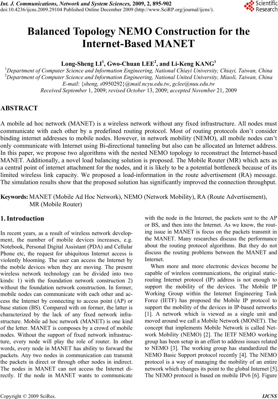 Int. J. Communications, Network and System Sciences, 2009, 2, 895-902 doi:10.4236/ijcns.2009.29104 Published Online December 2009 (http://www.SciRP.org/journal/ijcns/). Copyright © 2009 SciRes. IJCNS 895 Balanced Topology NEMO Construction for the Internet-Based MANET Long-Sheng LI1, Gwo-Chuan LEE2, and Li-Keng KANG1 1Department of Computer Science and Information Engineering, National Chiayi University, Chiayi, Taiwan, China 2Department of Computer Science and Information Engineering, National United University, Miaoli, Taiwan, China E-mail: {sheng, s0950292}@mail.ncyu.edu.tw, gclee@nuu.edu.tw Received September 1, 2009; revised October 13, 2009; accepted November 21, 2009 ABSTRACT A mobile ad hoc network (MANET) is a wireless network without any fixed infrastructure. All nodes must communicate with each other by a predefined routing protocol. Most of routing protocols don’t consider binding internet addresses to mobile nodes. However, in network mobility (NEMO), all mobile nodes can’t only communicate with Internet using Bi-directional tunneling but also can be allocated an Internet address. In this paper, we propose two algorithms with the nested NEMO topology to reconstruct the Internet-based MANET. Additionally, a novel load balancing solution is proposed. The Mobile Router (MR) which acts as a central point of internet attachment for the nodes, and it is likely to be a potential bottleneck because of its limited wireless link capacity. We proposed a load-information in the route advertisement (RA) message. The simulation results show that the proposed solution has significantly improved the connection throughput. Keywords: MANET (Mobile Ad Hoc Network), NEMO (Network Mobility), RA (Route Advertisement), MR (Mobile Router) 1. Introduction In recent years, as a result of wireless network develop- ment, the number of mobile devices increases, e.g. Notebook, Personal Digital Assistant (PDA) and Cellular Phone etc, the request for ubiquitous Internet access is violently blooming. The user can access the Internet by the mobile devices when they are moving. The present wireless network technology can be divided into two kinds: 1) with the foundation network construction 2) without the foundation network construction. In former, mobile nodes can communicate with each other and ac- cess the Internet by connecting to access point (AP) or base station (BS). Compared with on former, the latter is characterized by the lack of any fixed network infra- structure. Mobile ad hoc network (MANET) is one kind of the letter. MANET is composes by a crowd of mobile nodes. Without the support of fixed network infrastruc- ture, every node will play the role of router. In other words, every node in MANET has ability to forward the packets. Any two nodes in communication can transmit the packets in direct or through other nodes in indirect. The nodes in MANET can not access the Internet di- rectly. If the node in MANET wants to communicate with the node in the Internet, the packets sent to the AP or BS, and then into the Internet. As we know, the rout- ing issue in MANET is focus on the packets transmit in the MANET. Many researches discuss the performance about the routing protocol algorithms. But they do not discuss the routing problems between the MANET and Internet. When more and more electronic devices become be capable of wireless communications, the original static- routing Internet protocol (IP) address is not enough to support the mobility of the devices. The Mobile IP Working Group within the Internet Engineering Task Force (IETF) has proposed the Mobile IP protocol to support the mobility of the devices in IP-based networks [1]. A network which is viewed as a single unit and moved around we call a Mobile Network (MONET). The concept that implements Mobile Network is called Net- work Mobility (NEMO) [2]. The IETF NEMO working group has been setup in an effort to address issues related to NEMO [3]. The working group has standardized the NEMO Basic Support protocol recently [4]. The NEMO protocol is a way of managing the mobility of an entire network which changes its point to the global Internet [5]. The NEMO protocol is based on mobile IPv6 [6]. Figure 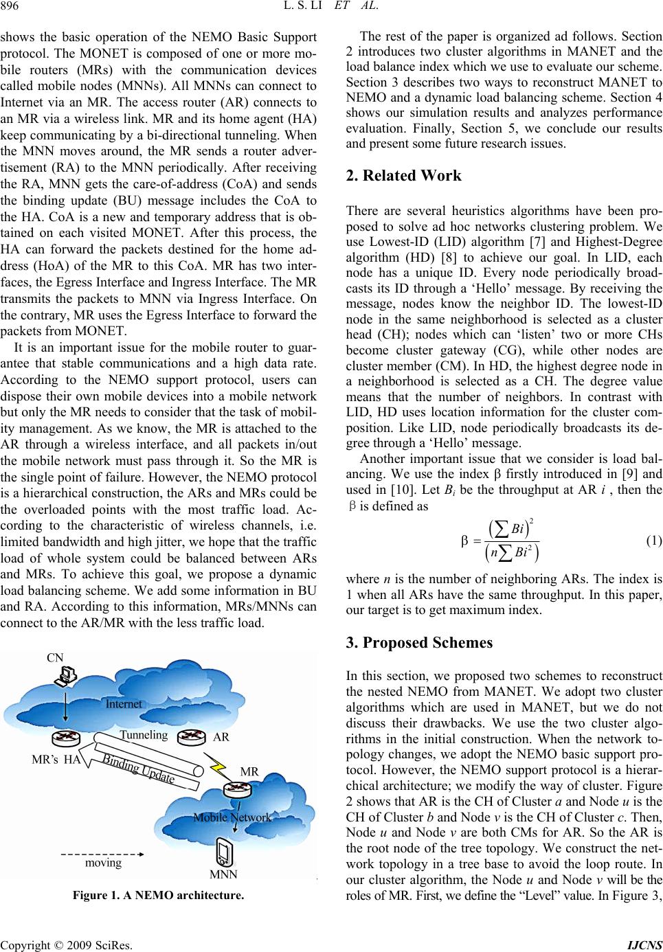 L. S. LI ET AL. Copyright © 2009 SciRes. IJCNS 896 shows the basic operation of the NEMO Basic Support protocol. The MONET is composed of one or more mo- bile routers (MRs) with the communication devices called mobile nodes (MNNs). All MNNs can connect to Internet via an MR. The access router (AR) connects to an MR via a wireless link. MR and its home agent (HA) keep communicating by a bi-directional tunneling. When the MNN moves around, the MR sends a router adver- tisement (RA) to the MNN periodically. After receiving the RA, MNN gets the care-of-address (CoA) and sends the binding update (BU) message includes the CoA to the HA. CoA is a new and temporary address that is ob- tained on each visited MONET. After this process, the HA can forward the packets destined for the home ad- dress (HoA) of the MR to this CoA. MR has two inter- faces, the Egress Interface and Ingress Interface. The MR transmits the packets to MNN via Ingress Interface. On the contrary, MR uses the Egress Interface to forward the packets from MONET. It is an important issue for the mobile router to guar- antee that stable communications and a high data rate. According to the NEMO support protocol, users can dispose their own mobile devices into a mobile network but only the MR needs to consider that the task of mobil- ity management. As we know, the MR is attached to the AR through a wireless interface, and all packets in/out the mobile network must pass through it. So the MR is the single point of failure. However, the NEMO protocol is a hierarchical construction, the ARs and MRs could be the overloaded points with the most traffic load. Ac- cording to the characteristic of wireless channels, i.e. limited bandwidth and high jitter, we hope that the traffic load of whole system could be balanced between ARs and MRs. To achieve this goal, we propose a dynamic load balancing scheme. We add some information in BU and RA. According to this information, MRs/MNNs can connect to the AR/MR with the less traffic load. Figure 1. A NEMO architecture. The rest of the paper is organized ad follows. Section 2 introduces two cluster algorithms in MANET and the load balance index which we use to evaluate our scheme. Section 3 describes two ways to reconstruct MANET to NEMO and a dynamic load balancing scheme. Section 4 shows our simulation results and analyzes performance evaluation. Finally, Section 5, we conclude our results and present some future research issues. 2. Related Work There are several heuristics algorithms have been pro- posed to solve ad hoc networks clustering problem. We use Lowest-ID (LID) algorithm [7] and Highest-Degree algorithm (HD) [8] to achieve our goal. In LID, each node has a unique ID. Every node periodically broad- casts its ID through a ‘Hello’ message. By receiving the message, nodes know the neighbor ID. The lowest-ID node in the same neighborhood is selected as a cluster head (CH); nodes which can ‘listen’ two or more CHs become cluster gateway (CG), while other nodes are cluster member (CM). In HD, the highest degree node in a neighborhood is selected as a CH. The degree value means that the number of neighbors. In contrast with LID, HD uses location information for the cluster com- position. Like LID, node periodically broadcasts its de- gree through a ‘Hello’ message. Another important issue that we consider is load bal- ancing. We use the index β firstly introduced in [9] and used in [10]. Let Bi be the throughput at AR i , then the βis defined as ( ) ( ) 2 2 Bi nBi β=∑ ∑ (1) where n is the number of neighboring ARs. The index is 1 when all ARs have the same throughput. In this paper, our target is to get maximum index. 3. Proposed Schemes In this section, we proposed two schemes to reconstruct the nested NEMO from MANET. We adopt two cluster algorithms which are used in MANET, but we do not discuss their drawbacks. We use the two cluster algo- rithms in the initial construction. When the network to- pology changes, we adopt the NEMO basic support pro- tocol. However, the NEMO support protocol is a hierar- chical architecture; we modify the way of cluster. Figure 2 shows that AR is the CH of Cluster a and Node u is the CH of Cluster b and Node v is the CH of Cluster c. Then, Node u and Node v are both CMs for AR. So the AR is the root node of the tree topology. We construct the net- work topology in a tree base to avoid the loop route. In our cluster algorithm, the Node u and Node v will be the roles of MR. First, we define the “Level” value. In Figure 3, 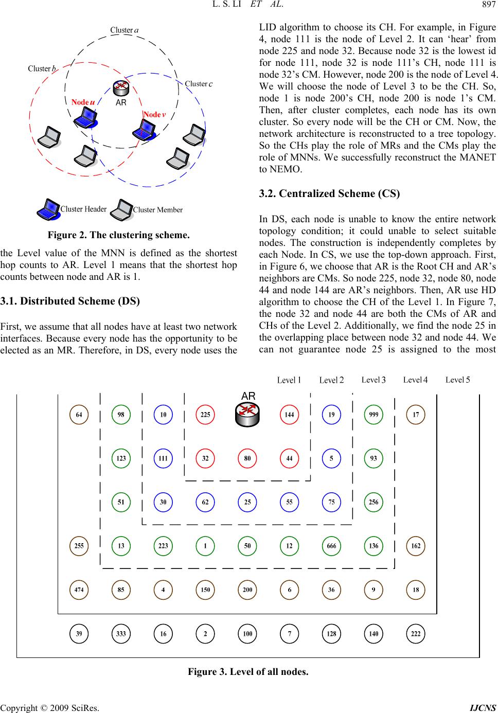 L. S. LI ET AL. Copyright © 2009 SciRes. IJCNS 897 Figure 2. The clustering scheme. the Level value of the MNN is defined as the shortest hop counts to AR. Level 1 means that the shortest hop counts between node and AR is 1. 3.1. Distributed Scheme (DS) First, we assume that all nodes have at least two network interfaces. Because every node has the opportunity to be elected as an MR. Therefore, in DS, every node uses the LID algorithm to choose its CH. For example, in Figure 4, node 111 is the node of Level 2. It can ‘hear’ from node 225 and node 32. Because node 32 is the lowest id for node 111, node 32 is node 111’s CH, node 111 is node 32’s CM. However, node 200 is the node of Level 4. We will choose the node of Level 3 to be the CH. So, node 1 is node 200’s CH, node 200 is node 1’s CM. Then, after cluster completes, each node has its own cluster. So every node will be the CH or CM. Now, the network architecture is reconstructed to a tree topology. So the CHs play the role of MRs and the CMs play the role of MNNs. We successfully reconstruct the MANET to NEMO. 3.2. Centralized Scheme (CS) In DS, each node is unable to know the entire network topology condition; it could unable to select suitable nodes. The construction is independently completes by each Node. In CS, we use the top-down approach. First, in Figure 6, we choose that AR is the Root CH and AR’s neighbors are CMs. So node 225, node 32, node 80, node 44 and node 144 are AR’s neighbors. Then, AR use HD algorithm to choose the CH of the Level 1. In Figure 7, the node 32 and node 44 are both the CMs of AR and CHs of the Level 2. Additionally, we find the node 25 in the overlapping place between node 32 and node 44. We can not guarantee node 25 is assigned to the most Figure 3. Level of all nodes. 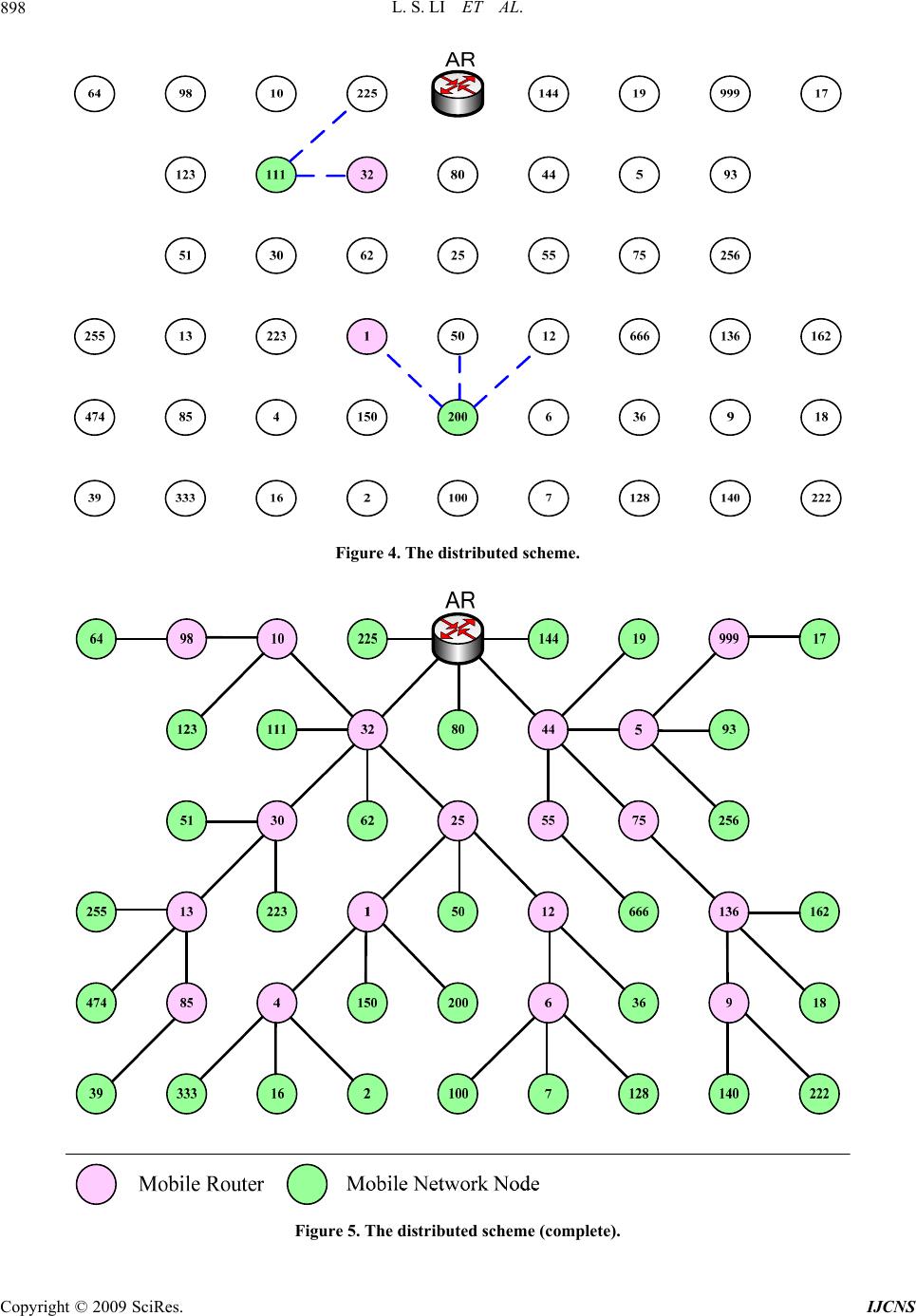 L. S. LI ET AL. Copyright © 2009 SciRes. IJCNS 898 Figure 4. The distributed scheme. Figure 5. The distributed scheme (complete).  L. S. LI ET AL. Copyright © 2009 SciRes. IJCNS 899 Figure 6. Centralized scheme (step 1). Figure 7. Centralized scheme (step 2).  L. S. LI ET AL. Copyright © 2009 SciRes. IJCNS 900 Figure 8. Centralized scheme (complete). suitable cluster. This will cause the load balance issue. We will discuss the Sub-Section 3.3. From top to down, every node is selected as a CM or CH. However, CMs play the roles of MNNs and CHs play the roles of MRs. 3.3. Load balancing Scheme (LBS) In Sub-Section 3.1 and Sub-Section 3.2, when the con- nection of the AR and the Internet fails, the communica- tion of a number of nodes in MONET is disconnected. For large MONET, which includes many MRs and MNNs, it will become a critical issue. In this section, we propose a scheme to achieve dynamic load balancing. In Figure 9, the load in/out in AR1 is 100kb/s, the load in/out in AR2 is 500kb/s. In the point of view for load balancing, the cluster-overlay node should be connecting to AR1. There are smaller packet load and nodes behind AR1 than AR2. But in NEMO basic support protocol, the cluster-overlay node receives the RA1 and the RA2 si- multaneously. It will send BU to it’s HA through AR1 or AR2. If the cluster-overlay node sends BU via AR2, the cluster-overlay node will communicate to CN with 100Kb/s, the total load in/out in AR2 is 600Kb/s. The load between AR1 and AR2 will be exceedingly unbal- anced. In Figure 10 is the RA message format defines in Mobile IPv6. There is no useful information to solve this problem. So we modify the RA message format to achieve our goal. Figure 9. The node between two Ars. Type Code Checksum Cur Hop Limit M O H Reserved Router Lifetime Reachable Time Retrans Timer Options Figure 10 . RA message format.  L. S. LI ET AL. Copyright © 2009 SciRes. IJCNS 901 Type Code Checksum Cur Hop Limit M O H Node_Num Router Lifetime Reachable Time Retrans Timer Options Options Type Length … … Options Type=11 Length Current Load Information Figure 11. RA message format that we proposed. In Figure 11, we add some information in “Reserved” and “Option”. The “Node_Num” is the number of nodes behind the AR/MR. The Current Load Information is the current packets load through the AR/MR. For Example, in Figure 9, the AR1 sends RA1 with “Node_Num = 1” and “Current Load Information = 100”, the AR2 sends the RA2 with “Node_Num = 3” and “Current Load In- formation = 500”. So the cluster-overlay node receives the RA1 and RA2 simultaneously, it will send the BU to it’s HA through AR1. Because the packets load of AR1 is smaller than AR2. 3.3.1. Traffic Load Balancing Two load balancing schemes are proposed. One is the traffic load balancing, another is node number balancing. Of course, the traffic load is the most important criterion in our scheme. In Figure, MR1 will send BU to MR1’s HA through AR1. We hope that the traffic load of AR1 and the traffic load of AR2 are equal. But it is impossible. So our goal is to reduce the load difference between two ARs. So that is why MR5 choose the AR with smaller load. 3.3.2. Node Number Balancing According to the load information, the node can choose the most appropriate AR/MR to connect. In Figure 13, the traffic load of AR1 is 110Kb/s and the traffic load of AR1 is 105Kb/s. The difference between two ARs is too small. Now, another criterion in our scheme is the num- ber of node. AR2 has three nodes and AR1 has only node. According to 3.3.1, the MR1 should connect to AR2. So AR2 will have six nodes and AR1 has only one node. If the MNN2, MNN3 and MNN4 will not increase their traffic load, it is not a matter. But the MNN2 increases 50Kb/s, MNN3 increases 50Kb/s and MNN4 increases 50Kb/s. The total traffic load of AR2 is 255Kb/s. In this situation, we hope that the MR1 connects to the AR with fewer nodes behinds it. So we propose the Node Number Balancing approach to solve this problem. If the differ- ence of two AR is less than 10% of total load, the node will connect to the AR/MR with fewer nodes behind it. 4. Simulation Results To evaluate the performance of the proposed schemes, we design a simulation program to calculate the per- formance. The simulation program is designed by Visual C++ in Windows XP. Table is the simulation parame- ters in our network topology. In Figure 14, the x-axis is the number of nodes; the y-axis is the value of LBI. According to the formula of LBI, the most ideal situation is the value of the LBI is 1. In our simulation, we assume that the total packet num- bers are proportionally increase by the node number. So the numbers of nodes increase the traffic load increase. But the LBI does not change. The reason is that the total packets proportionally increase, according to the formula of LBI, the LBI will not change. Additionally, the LBI of Figure 12. Traffic Load Balancing. Figure 13. Node balancing. Table 1. Simulation parameters. Room Size 500 (m) * 500 (m) The number of the Access Router 2 The position of the Access Router (125,125), (375,375) The number of nodes 50~200 The transmission range of nodes 180 (m) The average speed of nodes 10 (m/sec) The direction of nodes 360, Random The pause time of nodes 10 (sec) The interval of Router Advertisement 3 (sec) The interval of Hello Message 3 (sec) The transmission time of the data packet Exponential distributions, 300ms in average The simulation time 900 (sec)  L. S. LI ET AL. Copyright © 2009 SciRes. IJCNS 902 0.95 0.955 0.96 0.965 0.97 0.975 0.98 0.985 0.99 0.995 1 5075 100 125 150 175 200 The Number of Node LBI CS CS-TLP-LBS CS-NLP-LBS DS DS-TLP-LBS DS-NLP-LBS Figure 14. The LBI in different number of nodes (Speed = 10 m/s). 0.95 0.955 0.96 0.965 0.97 0.975 0.98 0.985 0.99 0.995 1 10 20 3040 50 The Average Speed (m/s) LBI CS CS-TLP-LBS CS-NLP-LBS DS DS-TLP-LBS DS-NLP-LBS Figure 15. The LBI in different speed (Node =100). CS (Centralized Scheme) and DS (Distributed Scheme) get improvement when the number of nodes increases. In fact, the unbalancing situation does not get improvement. The reason is that the throughput of one AR is getting down by the packet loss which causes by the limited bandwidth. The packet loss of one AR will cause the difference of throughput of two AR becoming small. That will cause the LBI to get improvement. In Figure 15, the x-axis is the average speed; the y-axis is the value of LBI. In the original schemes, the nodes can connect to the router with less traffic load. It will cause the unbalancing situation. As the nodes mov- ing faster, the situation does not change more. The rea- son is the unbalancing situation will alleviate by the moving speed of nodes. In TLP-LBS, we can get the better value of the LBI. The reason is that the nodes connect to the router with less traffic load. In NLP-LBS, the nodes connect to the router with fewer nodes. The router maybe has more traffic load. In this situation, that will cause the router to get more traffic load afterwards. 5. Conclusions and Future Work In this paper, we propose the two algorithms of recon- struction from MANET to NEMO and the dynamic load balancing scheme. We adopt two cluster algorithms which used in MANET. In the NEMO basic support protocol, the node receives the RA message without any useful information and then sends the BU to it’s HA. The node can not choose the most suitable point to connect. In LBA, we put some useful load information into the RA message. According this information, the node in overlapping place between two routers, it will connect to the less loaded router. We hope that the packets load between routers is balanced. The simulation results show that our approach can achieve large performance im- provement. The evaluation performed in this paper is just prelimi- nary. NEMO provides ubiquitous communications with network access. Therefore, all groups of communication nodes can move as a single unit. We must evaluate the proposed scheme with more realistic condition. e.g., the nodes with the different movement speed. In the future work, we will evaluate the end-to-end delay and packet delivery ratio. 6. References [1] D. Johnson, C. Perkins, and J. Arkko, “Mobility support in IPv6,” Network Working Group, RFC3775, June 2004. [2] T. Ernst and H. Y. Lach, “Network mobility support ter- minology,” Internet Draft drafr-ietf-nemo-terminology- 03.txt, February 2005. [3] The IETF NEMO working group, As of April 2005. http://www.ietf.org/html.charters/nemocharter.html. [4] V. Devarapalli, et al., “Network mobility (NEMO) basic support protocol,” Request for Comments: 3963, IETF, January 2005. [5] T. Ernst and H. Lach, “Network mobility support termi- nology,” Internet draft, February 2005. [Online]. Avail- able: http://ietfreport.isoc.org/idref/draft-ietf-nemo-ter- minology [6] D. Johnson, et. al., “Mobility support in IPv6,” Inter- net-Draft, draft-ietf-mobileip-ipv6-24.txt, Internet Engi- neering Task Force (IETF), Work in Progress, June 2003. [7] C. R. Li and G. Mario, “Adaptive clustering for mobile wireless networks,” IEEE Journal of Selected Areas in Communications, Vol. 15, No. 7, pp. 1265–1275, Sep- tember 1997. [8] M. Gerla and J. T. C. Tsai, “Multicluster, mobile, multi- media radio network,” Wireless Networks, Vol. 1, No. 3, pp. 255–265, 1995. |