Paper Menu >>
Journal Menu >>
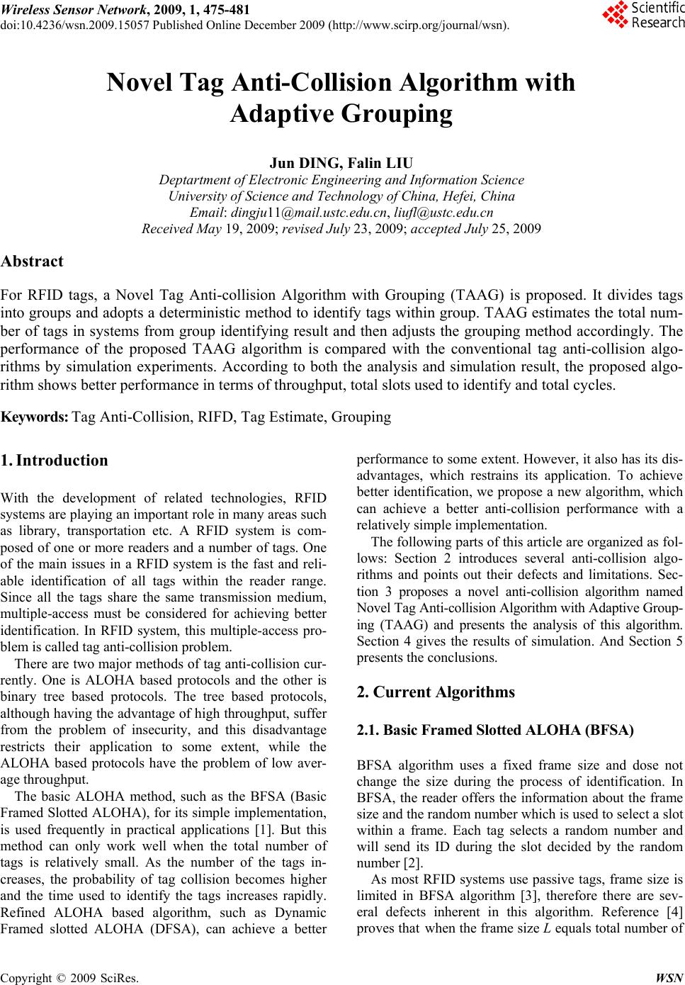 Wireless Sensor Network, 2009, 1, 475-481 doi:10.4236/wsn.2009.15057 Published Online December 2009 (http://www.scirp.org/journal/wsn). Copyright © 2009 SciRes. WSN Novel Tag Anti-Collision Algorithm with Adaptive Grouping Jun DING, Falin LIU Deptartment of Electronic Engineering and Information Science University of Science and Technology of China, Hefei, China Email: dingju11@mail.ustc.edu.cn, liufl@ustc.edu.cn Received May 19, 2009; revised July 23, 2009; accepted July 25, 2009 Abstract For RFID tags, a Novel Tag Anti-collision Algorithm with Grouping (TAAG) is proposed. It divides tags into groups and adopts a deterministic method to identify tags within group. TAAG estimates the total num- ber of tags in systems from group identifying result and then adjusts the grouping method accordingly. The performance of the proposed TAAG algorithm is compared with the conventional tag anti-collision algo- rithms by simulation experiments. According to both the analysis and simulation result, the proposed algo- rithm shows better performance in terms of throughput, total slots used to identify and total cycles. Keywords: Tag Anti-Collision, RIFD, Tag Estimate, Grouping 1. Introduction With the development of related technologies, RFID systems are playing an important role in many areas such as library, transportation etc. A RFID system is com- posed of one or more readers and a number of tags. One of the main issues in a RFID system is the fast and reli- able identification of all tags within the reader range. Since all the tags share the same transmission medium, multiple-access must be considered for achieving better identification. In RFID system, this multiple-access pro- blem is called tag anti-collision problem. There are two major methods of tag anti-collision cur- rently. One is ALOHA based protocols and the other is binary tree based protocols. The tree based protocols, although having the advantage of high throughput, suffer from the problem of insecurity, and this disadvantage restricts their application to some extent, while the ALOHA based protocols have the problem of low aver- age throughput. The basic ALOHA method, such as the BFSA (Basic Framed Slotted ALOHA), for its simple implementation, is used frequently in practical applications [1]. But this method can only work well when the total number of tags is relatively small. As the number of the tags in- creases, the probability of tag collision becomes higher and the time used to identify the tags increases rapidly. Refined ALOHA based algorithm, such as Dynamic Framed slotted ALOHA (DFSA), can achieve a better performance to some extent. However, it also has its dis- advantages, which restrains its application. To achieve better identification, we propose a new algorithm, which can achieve a better anti-collision performance with a relatively simple implementation. The following parts of this article are organized as fol- lows: Section 2 introduces several anti-collision algo- rithms and points out their defects and limitations. Sec- tion 3 proposes a novel anti-collision algorithm named Novel Tag Anti-collision Algorithm with Adaptive Group- ing (TAAG) and presents the analysis of this algorithm. Section 4 gives the results of simulation. And Section 5 presents the conclusions. 2. Curren t Al gor ithms 2.1. Basic Framed Slotted ALOHA (BFSA) BFSA algorithm uses a fixed frame size and dose not change the size during the process of identification. In BFSA, the reader offers the information about the frame size and the random number which is used to select a slot within a frame. Each tag selects a random number and will send its ID during the slot decided by the random number [2]. As most RFID systems use passive tags, frame size is limited in BFSA algorithm [3], therefore there are sev- eral defects inherent in this algorithm. Reference [4] proves that when the frame size L equals total number of 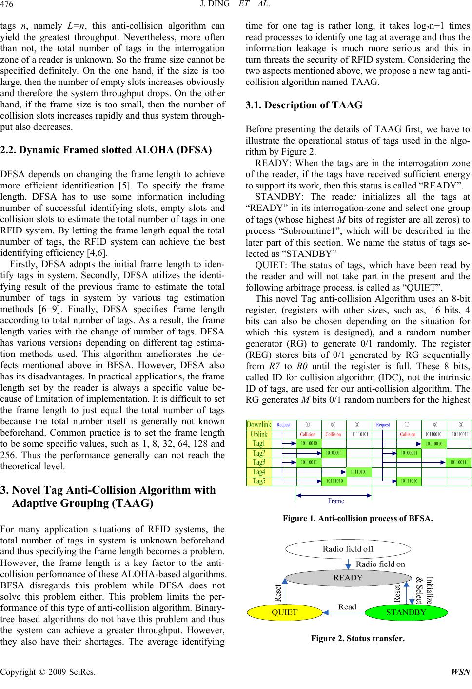 J. DING ET AL. 476 tags n, namely L=n, this anti-collision algorithm can yield the greatest throughput. Nevertheless, more often than not, the total number of tags in the interrogation zone of a reader is unknown. So the frame size cannot be specified definitely. On the one hand, if the size is too large, then the number of empty slots increases obviously and therefore the system throughput drops. On the other hand, if the frame size is too small, then the number of collision slots increases rapidly and thus system through- put also decreases. 2.2. Dynamic Framed slotted ALOHA (DFSA) DFSA depends on changing the frame length to achieve more efficient identification [5]. To specify the frame length, DFSA has to use some information including number of successful identifying slots, empty slots and collision slots to estimate the total number of tags in one RFID system. By letting the frame length equal the total number of tags, the RFID system can achieve the best identifying efficiency [4,6]. Firstly, DFSA adopts the initial frame length to iden- tify tags in system. Secondly, DFSA utilizes the identi- fying result of the previous frame to estimate the total number of tags in system by various tag estimation methods [6−9]. Finally, DFSA specifies frame length according to total number of tags. As a result, the frame length varies with the change of number of tags. DFSA has various versions depending on different tag estima- tion methods used. This algorithm ameliorates the de- fects mentioned above in BFSA. However, DFSA also has its disadvantages. In practical applications, the frame length set by the reader is always a specific value be- cause of limitation of implementation. It is difficult to set the frame length to just equal the total number of tags because the total number itself is generally not known beforehand. Common practice is to set the frame length to be some specific values, such as 1, 8, 32, 64, 128 and 256. Thus the performance generally can not reach the theoretical level. 3. Novel Tag Anti-Collision Algorithm with Adaptive Grouping (TAAG) For many application situations of RFID systems, the total number of tags in system is unknown beforehand and thus specifying the frame length becomes a problem. However, the frame length is a key factor to the anti- collision performance of these ALOHA-based algorithms. BFSA disregards this problem while DFSA does not solve this problem either. This problem limits the per- formance of this type of anti-collision algorithm. Binary- tree based algorithms do not have this problem and thus the system can achieve a greater throughput. However, they also have their shortages. The average identifying time for one tag is rather long, it takes log2n+1 times read processes to identify one tag at average and thus the information leakage is much more serious and this in turn threats the security of RFID system. Considering the two aspects mentioned above, we propose a new tag anti- collision algorithm named TAAG. 3.1. Description of TAAG Before presenting the details of TAAG first, we have to illustrate the operational status of tags used in the algo- rithm by Figure 2. READY: When the tags are in the interrogation zone of the reader, if the tags have received sufficient energy to support its work, then this status is called “READY”. STANDBY: The reader initializes all the tags at “READY” in its interrogation-zone and select one group of tags (whose highest M bits of register are all zeros) to process “Subrountine1”, which will be described in the later part of this section. We name the status of tags se- lected as “STANDBY” QUIET: The status of tags, which have been read by the reader and will not take part in the present and the following arbitrage process, is called as “QUIET”. This novel Tag anti-collision Algorithm uses an 8-bit register, (registers with other sizes, such as, 16 bits, 4 bits can also be chosen depending on the situation for which this system is designed), and a random number generator (RG) to generate 0/1 randomly. The register (REG) stores bits of 0/1 generated by RG sequentially from R7 to R0 until the register is full. These 8 bits, called ID for collision algorithm (IDC), not the intrinsic ID of tags, are used for our anti-collision algorithm. The RG generates M bits 0/1 random numbers for the highest Figure 1. Anti-collision process of BFSA. Figure 2. Status transfer. Copyright © 2009 SciRes. WSN 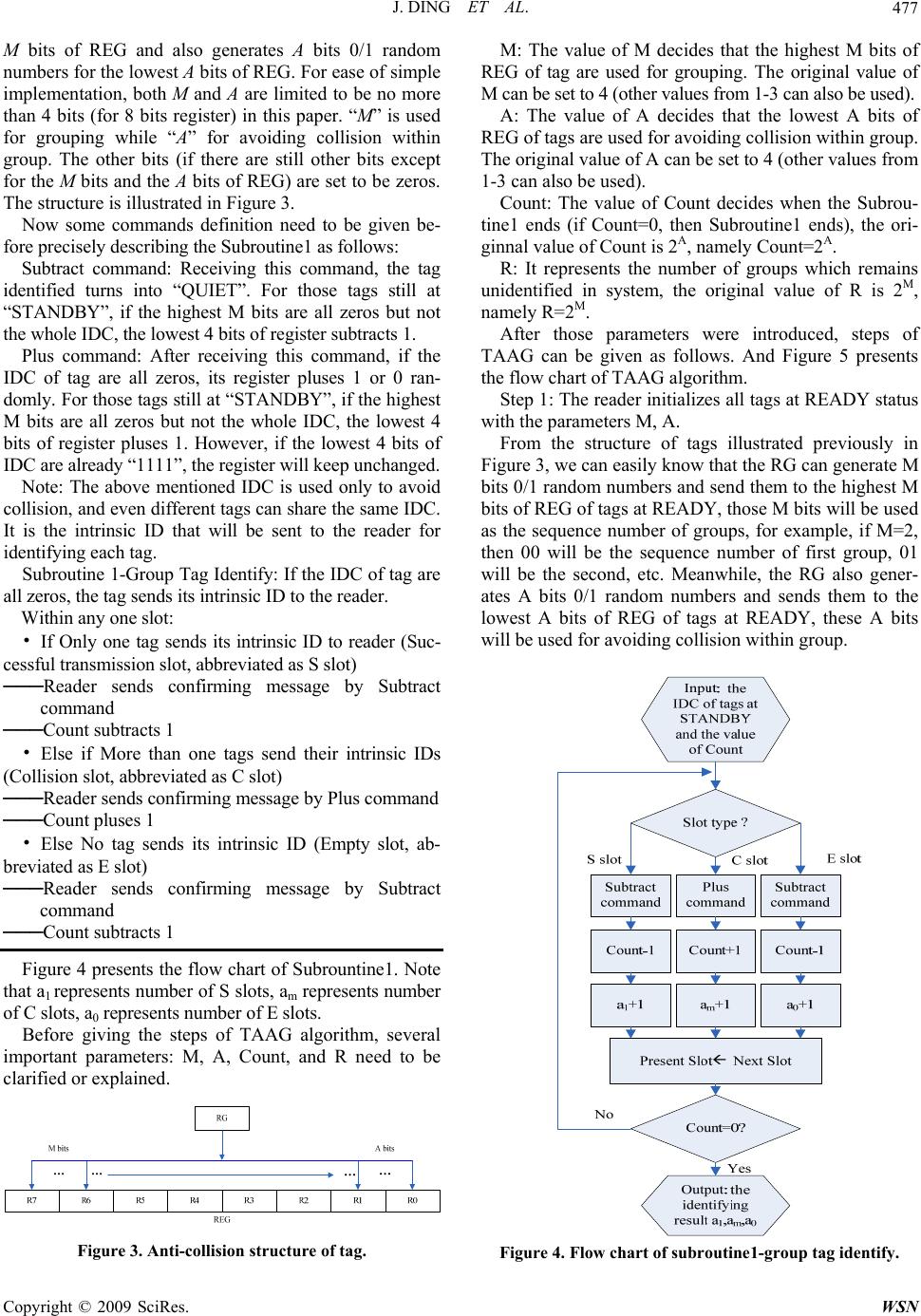 J. DING ET AL.477 M bits of REG and also generates A bits 0/1 random numbers for the lowest A bits of REG. For ease of simple implementation, both M and A are limited to be no more than 4 bits (for 8 bits register) in this paper. “M” is used for grouping while “A” for avoiding collision within group. The other bits (if there are still other bits except for the M bits and the A bits of REG) are set to be zeros. The structure is illustrated in Figure 3. Now some commands definition need to be given be- fore precisely describing the Subroutine1 as follows: Subtract command: Receiving this command, the tag identified turns into “QUIET”. For those tags still at “STANDBY”, if the highest M bits are all zeros but not the whole IDC, the lowest 4 bits of register subtracts 1. Plus command: After receiving this command, if the IDC of tag are all zeros, its register pluses 1 or 0 ran- domly. For those tags still at “STANDBY”, if the highest M bits are all zeros but not the whole IDC, the lowest 4 bits of register pluses 1. However, if the lowest 4 bits of IDC are already “1111”, the register will keep unchanged. Note: The above mentioned IDC is used only to avoid collision, and even different tags can share the same IDC. It is the intrinsic ID that will be sent to the reader for identifying each tag. Subroutine 1-Group Tag Identify: If the IDC of tag are all zeros, the tag sends its intrinsic ID to the reader. Within any one slot: • If Only one tag sends its intrinsic ID to reader (Suc- cessful transmission slot, abbreviated as S slot) ───Reader sends confirming message by Subtract command ───Count subtracts 1 • Else if More than one tags send their intrinsic IDs (Collision slot, abbreviated as C slot) ───Reader sends confirming message by Plus command ───Count pluses 1 • Else No tag sends its intrinsic ID (Empty slot, ab- breviated as E slot) ───Reader sends confirming message by Subtract command ───Count subtracts 1 Figure 4 presents the flow chart of Subrountine1. Note that a1 represents number of S slots, am represents number of C slots, a0 represents number of E slots. Before giving the steps of TAAG algorithm, several important parameters: M, A, Count, and R need to be clarified or explained. Figure 3. Anti-collision structure of tag. M: The value of M decides that the highest M bits of REG of tag are used for grouping. The original value of M can be set to 4 (other values from 1-3 can also be used). A: The value of A decides that the lowest A bits of REG of tags are used for avoiding collision within group. The original value of A can be set to 4 (other values from 1-3 can also be used). Count: The value of Count decides when the Subrou- tine1 ends (if Count=0, then Subroutine1 ends), the ori- ginnal value of Count is 2A, namely Count=2A. R: It represents the number of groups which remains unidentified in system, the original value of R is 2M, namely R=2M. After those parameters were introduced, steps of TAAG can be given as follows. And Figure 5 presents the flow chart of TAAG algorithm. Step 1: The reader initializes all tags at READY status with the parameters M, A. From the structure of tags illustrated previously in Figure 3, we can easily know that the RG can generate M bits 0/1 random numbers and send them to the highest M bits of REG of tags at READY, those M bits will be used as the sequence number of groups, for example, if M=2, then 00 will be the sequence number of first group, 01 will be the second, etc. Meanwhile, the RG also gener- ates A bits 0/1 random numbers and sends them to the lowest A bits of REG of tags at READY, these A bits will be used for avoiding collision within group. Figure 4. Flow chart of subroutine1-group tag ide ntify. Copyright © 2009 SciRes. WSN 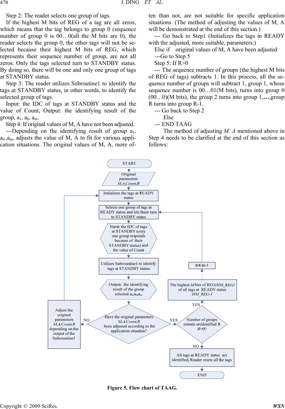 J. DING ET AL. Copyright © 2009 SciRes. WSN 478 Step 2: The reader selects one group of tags. If the highest M bits of REG of a tag are all zeros, which means that the tag belongs to group 0 (sequence number of group 0 is 00…0(all the M bits are 0), the reader selects the group 0, the other tags will not be se- lected because their highest M bits of REG, which represents their sequence number of group, are not all zeros. Only the tags selected turn to STANDBY status. By doing so, there will be one and only one group of tags at STANDBY status. Step 3: The reader utilizes Subroutine1 to identify the tags at STANDBY status, in other words, to identify the selected group of tags. Input: the IDC of tags at STANDBY status and the value of Count, Output: the identifying result of the group, a1, a0, am. Step 4: If original values of M, A have not been adjusted. ---Depending on the identifying result of group a1, a0 ,am, adjusts the value of M, A to fit for various appli- cation situations. The original values of M, A, more of- ten than not, are not suitable for specific application situations. (The method of adjusting the values of M, A will be demonstrated at the end of this section.) --- Go back to Step1 (Initializes the tags in READY with the adjusted, more suitable, parameters.) Else if original values of M, A have been adjusted ---Go to Step 5 Step 5: If R>0 --- The sequence number of groups (the highest M bits of REG of tags) subtracts 1. In this process, all the se- quence number of groups will subtract 1, group 1, whose sequence number is 00…01(M bits), turns into group 0 (00…0)(M bits), the group 2 turns into group 1,…,group R turns into group R-1. --- Go back to Step 2 Else --- END TAAG The method of adjusting M, A mentioned above in Step 4 needs to be clarified at the end of this section as follows: Figure 5. Flow chart of TAAG.  J. DING ET AL. Copyright © 2009 SciRes. WSN 479 Define each combination of the lowest A bits of REG of tags as one Bin, then the number of Bins is 2A. If this number equals the number of tags n within a group, i.e. n=2A, the system can achieve the best performance. Based on this, we can specify the value of A. The proof is basically the same as that of Slotted ALOHA [4–6,9]. When the possibility of S slot is the largest, the system can achieve best performance because both Collision slots and Empty slots degrade the per- formance of system. Let L=2A,, then the probability of occurrence that a Bin is occupied by only one tag (S slot) can be written as: 11 1 11 ()(1 ) n n pC 1 L L (1) To get the maximum value of p1, differentiate p1 with L, 2 1 1 ()(1) 0 n n dp nnL L dL L (2) We can find n=L easily. According to the above prin- ciple, we can adjust M, A, Count= 2A and R=2M appro- priately as illustrated in Table. 1. If the total number of tags can not be found in Tab.1, we can substitute it with the closest value. After the val- ues of M, A were adjusted, the values of Count, R are changed accordingly. 3.2. Analysis of TAAG This algorithm groups tags at the very beginning, and this process possesses lots of advantages. Firstly, group- ing tags can decrease the collision because of smaller number of tags within one group, especially when the total number of tags in system is large. Secondly, identi- fying one group of tags can bring us useful information about the estimation of total tags number, and based on the information, we can adjust the parameters of our anti-collision algorithm appropriately so that it can fit for various applications Furthermore, the algorithm utilizes Subroutine1-Group Tag Identify to identify the tags within group. There are also many advantages: Table 1. Adjust the values of M, A. A4 3 2 M 1 4 n>=256 3 n=128 2 n=64 1 n=32 n=16 n=8 n<=4 1) The implementation is simple, which is beneficial for the extensive application of this tag anti-collision algorithm. 2) Subroutine1 can identify all the tags in system and no tag will be unidentified. This solves the problem ex- isting in the ALOHA-based algorithm where a tag may be regarded as out of the reader’s interrogation zone if it can not be identified for a long period. In Subroutine1, if a slot is S slot, then Coun t -1, while if the slot is C slot, the Count+1. If there are x C slots, then Count+x. As a result, Subroutine1 can guarantee that all tags can be identified. Example to illustrate such a process is shown in Table 2. In the example, A=2, Count=2A=4, the lowest 4 bits are used for avoiding collision within group and there will be 16 Bins. The 0000 represents Bin1, similarly, we can get other Bins codes like Bin1. T1 represents tag No.1, T2 represents tag No.2, etc. According to Sub- rountine1, the tags T1, T2, T3 in Bin1 should first be identified, but now they are in the collision Slot. So the IDCs of T1, T2, T3 should plus 0/1 randomly. Because the result has many possibilities, here in Tab. 2 only one possibility is illustrated. The multiple possibilities will also exist when identifying T1 and T2 in Bin1 at Slot 2. Here we choose the possibility that uses the least number of slots, just to show how the algorithm works. 3) Adopting Subroutine1, we can get the estimation of tags remaining unidentified depending on the a1, a0, am acquired from the first group’s identification. Since all tags can be identified in Subroutine1, the number of S slots a1 must equal the number of tags within group. 4. Results Before presenting the results of TAAG, three main issues involved in tag anti-collision algorithm performance should be kept in mind: Table 2. Subroutine1 identifying proc ess. Slot Slot1 Slot2 Slot3 Slot4 Slot5 Slot6 Slot7 Slot8 Count=4(c) Count+1=5Count+1=6 Count-1=5Count-1=4Count-1=3Count-1=2Count-1=1 Count-1=0 Uplink Collision Collision T1 T2 T3 T5 Empty T4 Bin1(0000) T1, T2, T3T1, T2 T1 T2 T3 T5 T4 Bin2(0001) T5 T3 T2 T3 T5 T4 Bin3(0010) T5 T3 T5 T4 Bin4(0011) T4 T5 T4 Bin5(0100) T4 T4 Bin6(0101) T4  J. DING ET AL. 480 Throughput: the ratio of S slots to the sum of S, E, C slots. The Throughput expresses the ratio of usage of channel. S Througput SEC (3) Number of slots (NOS): Total number of slots used to read all the tags. Smaller NOS means that reader can identify all the tags in fewer numbers of slots. In other words, the speed of read process will be fast. Required Cycles: More required cycles mean that the system spends more time dealing with the communica- tion handshaking between the reader and tags, which is detrimental for the identifying speed of tag anti-collision algorithm. Now we will show the performance of TAAG. In the following simulation, the original parameter “M=4”, “A=4”, L represents the frame size and the simulations are based on Monte Carlo technique. 1) From Figure 6, we may find that if the total number of tags in system is small, BFSA (L=128) have larger throughput than BFSA (L=256). However, with the in- crease of the number of tags in system, BFSA (L=256) performs better. Figure 6 vividly depicts that DFSA has a larger throughput than BFSA. However, since the limita- tion of implementation of DFSA in practical application (mentioned in Subection 2.2), the throughput of DFSA is close to that of the BFSA (L=256) with the increase of tags in system. The algorithm we proposed, TAAG, has the best performance in throughput. The throughput of this algorithm reaches to the level of about 0.4 when the total number of tags varies in a large range (form 30 to 1,000). 2) From Figure 7, we can observe that BFSA (L=128) needs more slots to identify the same number of tags (If the number of tags is relatively large). When the number of tags in system is small, DFSA needs fewer slots than BFSA (L=256). However, with the increase of number of tags in system, the performance of DFSA is close to BFSA (L=256), as was stated in Subsection 2.2. The total number of slots, which TAAG uses to identify 1,000 tags in system, is about 2800 while BFSA (L=256) (or DFSA) has to use about 5500 slots. It is obvious that TAAG has advantage in terms of the number of slots used to identify. 3) From Figure 8, we conclude that TAAG only needs communication handshakes with tags for 2 times, which improves the identifying speed of RFID system for cer- tain. 5. Conclusions We proposed and analyzed Novel Tag Anti-collision Algorithm with Grouping (TAAG). According to the analysis and simulation, we can obtain the following conclusions. Firstly, TAAG anti-collision algorithm has Figure 6. Throughput vs. numbe r of tags. Figure 7. Number of cycles vs. number of tags. Figure 8. Number of slots vs. number of tags. Copyright © 2009 SciRes. WSN  J. DING ET AL. Copyright © 2009 SciRes. WSN 481 obvious superiority in terms of all these three parameters of performance, the throughput, the number of slots and the required cycles. Secondly, the implementation of the algorithm is rather simple. The complexity of realization is at the same level as BFSA algorithm. Although the implementation of Reader is relatively complicated, the number of reader in a RFID system is far smaller than the number of tags, so the cost for the whole RFID sys- tem will not be changed greatly. Thirdly, compared with Binary-tree based algorithm, TAAG also has its superi- ority in terms of lower cost and less average time needed to identify a single tag. Finally, the applicability of TAAG is another merit. TAAG can be used for different number of tags in RFID system. And the system can achieve a good performance. Furthermore, because number of slots used to identify is rather small, the iden- tifying speed of RFID system is high. So TAAG can be used in fast identification situations. In summary, TAAG, as a tag anti-collision algorithm, owns its advantages in some applications and deserves to be applied in various RFID systems. 6. References [1] K. Finkenzeller, “RFID handbook,” Second Edition, JOHN WILEY & SONS, pp. 195–219, 2003. [2] PHILIPS Semiconductor, “I-CODEI system design guide: Technical report,” May 2002. [3] S.-R. Lee, S,-D. Joo, and C,-W, Lee, “An enhanced dy- namic framed slotted ALOHA algorithm for RFID tag identification,” The Second Annual International Con- ference on Mobile and Ubiquitous Systems: Networking and Service, pp. 166–172, 17–21 July 2005. [4] W.-T. Chen, “An accurate tag estimate method for im- proving the performance of an RFID anticollision algo- rithm based on dynamic frame length ALOHA,” IEEE Transactions on Automation Science And Engineering, Vol. 6, No. 1, pp. 9–15, January 2009. [5] F. C. Schoute, “Dynamic frame length ALOHA,” IEEE Transactions on Communications, Vol. 31, No. 4, pp. 565–568, April, 1983. [6] J.-R. Cha and J.-H. Kim, “Novel anti-collision algorithm for fast object identification in RFID system,” ICPADS’ 05, Vol. 2, pp. 63–67, 22–22 July 2005. [7] H. Vogt, “Efficient object identification with passive rfid tags,” Lecture Notes in Computer Science, Pervasive Computing, Vol. 2414, pp. 8–113, January 2002. [8] D. K. Klair, K.-W. Chin, and R. Raad, “On the accuracy of RFID tag estimation functions,” International Sympo- sium on Communication and Information Technologies, ISICT’07, pp. 1401–1406, 17–19 October 2007. [9] H. Vogt, “Multiple object identification with passive RFID tags,” IEEE International Conference on Systems, Man and Cybernetics, Vol. 3, 6–9 October 2002. |