Paper Menu >>
Journal Menu >>
 Vol.1, No.3, 222-228 (2009) doi:10.4236/ns.2009.13030 SciRes Copyright © 2009 Openly accessible at http://www.scirp.org/journal/NS/ Natural Science Control strategy optimization using dynamic programming method for synergic electric system on hybrid electric vehicle Yuan-Bin Yu, Qing-Nian Wang, Hai-Tao Min, Peng-Yu Wang, Chun-Guang Hao The State Key Laboratory of Automobile Dynamic Simulation, JiLin University, Changchun, China Received 23 August 2009; revised 27 September 2009; accepted 22 October 2009. ABSTRACT Dynamic Programming (DP) algorithm is used to find the optimal trajectories under Beijing cycle for the power management of synergic electric system (SES) which is composed of battery and super capacitor. Feasible rules are derived from analyzing the optimal trajectories, and it has the highest contribution to Hybrid Electric Vehicle (HEV). The methods of how to get the best performance is also educed. Using the new Rule-based power management strat- egy adopted from the optimal results, it is easy to demonstrate the effectiveness of the new strategy in further improvement of the fuel economy by the synergic hybrid system. Keywords: Dynamic Programming; Control Strategy; Optimization; Synergic Electric System; HEV 1. INTRODUCTION Hybrid Electric Vehicle (HEV) could improve fuel economy and exhaust emission using the electric system to adjust the load of engine and could make it work in high efficiency. But this depends on the performance of the electric system on board. Because of the low power density of battery, it’s hard to be competent for this pur- pose. When it was combined with super capacitor to form a new electric system which was called the Syner- gic Electric System (SES), could exert both merits, which is energy and power density [1,2]. Rule-based or fuzzy logic control strategy was used to supervise the power flow between the two parts at pre- sent [3,4]. For every state of the SES, each control will come to a new state,at the same time, we can get a loss of energy. With regard to a given cycle of motor power requirement, how to get the best control rate has been put to us which can achieve the optimal performance of the system. Dynamic Programming is a numerical methodology developed for solving sequential or multi- stage decision problems just like the SES. The algorithm searches for optimal decisions at discrete points in a time sequence. It has been shown to be a powerful tool for optimal control in various application areas [4,5,6,7]. The dissertation proposed the dynamic programming algorithm from optimum control theory which solve the problem of overall control rate for SES in the whole cycle and try to answer the question like what can SES do on energy-saving. 2. BRIEF INTRODUCTION OF SES CONFIGURATION AND RULE-BASED CONTROL ALGORITHM A hybrid city bus was chosen as a researching flat, and the SES was made up of 280 Nickel-Hydrogen batteries units (1.2V\15Ah each) and 120 super capacitors (2.5V \2000F each). A Buck/ Boost DC/DC power converter whose Peak / rated power were 60/30kw was used in this system to coordinate the voltage of battery and capacitor, and to control the current of capacitor actively. Figure 1 was the layout of SES in this research. Control objective of SES was as follow: ensure the vehi- cle’s dynamic as the premise and give full play to the super capacitor’s “push and pull” role; decrease large current’s impact; extent battery’s service life; regenerate braking energy as much as possible to improve fuel Figure 1. Topology of Buck/Boost DC/DC Converter.  Y. B. Yu et al. / Natural Science 1 (2009) 222-228 SciRes Copyright © 2009 Openly accessible at http://www.scirp.org/journal/NS/ 223 economy. The principle of the rule-based control strat- egy is: During the operation, battery provides the aver- age power requirement; capacitor will give a comple- ment. The control rule was as follow: 1) if Pm<0, and super capacity was not over charged, then Pbat=0; 2) or if Pm <Pbat_max, and super capacity was not over discharged, then Pbat=Pfilter、Pscap=Pm-Pfilter; 3) otherwise Pbat=Pm; 4) when super capacity run out of energy, charge the capacitor from battery, Pbat =Pchg+Pbat. The variables’ meanings above are: Pm——the power required from motor, Pbat ——batteries’ power needed from motor, Pscap ——capacitor’s power requirement, Pfilter——filtering power, which is calculated by For- mula (1). '' mm 1 t filter LP PPHPe ' 1 tt load Pe e (1) In the formula: Pload——road resistance; HLP——filter function; τ、τ’——engine and battery’s low-pass filter time constant; t——acceleration time; Pm——motor power required; Pchg——charge power from battery when capacitor’s state of charge (CSOC) is low. It is the function of battery’s state of charge (SOC) and is equal to Pbat_max*(SOC-SOCmin)/ (SOCmax-SOCmin). The capacitor’s electrical-quantity shortage is deter- mined by the demand. When the actual voltage of ca- pacitor is lower than the ideal voltage, it is calculated out according to vehicle speed as Formula (2). The disserta- tion provides that the ideal voltage limit is in a reverse proportion with vehicle speed. The object of setting this value is to develop a goal of electrical-quantity for ca- pacitor, which could ensure that it could preserve enough energy for acceleration when vehicle speed is in the formula: Vscap——capacitor’s actual voltage of low and regenerate enough braking energy capacity. When vehicle speed is high. The speed requirement of the ve- hicle, the current of single battery, current of SES’s bat- tery and capacitor according to rule-based control strat- egy are shown in Figure 2. 2 max max V1 scap car scap car v k Vv (2) In the formula: capacitor; max s cap V——capacitor’s maximum voltage; vcar——actual vehicle speed; max car v ——maximum vehicle speed; k——capacitor’s energy utilization rate in cycle, in value equivalent to 0.75; Figure 2. Simulation results under Beijing cycle. 3. BRIEF INTRODUCTION OF DYNAMIC PROGRAMMING CONTROL ALGORITHM Dynamic programming is a kind of math method solving the optimal problem in process of multi-stage decision. It is proposed and established in the Fifties of 20th Cen- tury by American mathematicians (Bellman) who claim the famous Optimum Theory and transmit the process of multi-decision into a serious of single-stage issue. Multi- stage problem is a kind of activities which could be di- vided into several interrelated stages. Each stage needs a decision. The decision not only decides the benefit of this stage but also the initial state of next stage. A se- quence of decisions would be created after every stage’s decision has been made. The multi-stage decision prob- lem is to get a control strategy that can optimize the sum of every stage’s benefit [3]. Dynamic programming al- gorithm can fully utilize the limited resources which is an important content of investment-determination. As for multi-stage determination problem, dynamic pro- gramming method could be used to make sure the sum of benefit from every stage optimal [4]. 4. DESCRIPTION OF PROBLEM OF OPTIMIZATION CONTROL ALGORITHM The power requirement of motor at every moment is fulfilled by battery and ultra capacitor. However, be- cause of the difference between the resistance and the efficiency of charge and discharge, every decision made by system at every moment will create impact on the whole control effect. For the power requirement of mo- tor is consist of the power of battery and ultra capacitor at any proportion. So relationship of the power of battery and ultra capacitor is:  Y. B. Yu et al. / Natural Science 1 (2009) 222-228 SciRes Copyright © 2009 http://www.scirp.org/journal/NS/ 224 b at scap m P +P=P (3) Figure 3. Recursive of system’s state and control object.as shown in Formula (6). Every moment, the battery and ultra capacitor in the SES have the corresponding SOC and CSOC which rep- resent the state X of battery and ultra capacitor. When the power flow through battery and ultra capacitor, it can create an incentive to change the state of the two power source, at the same time can create power loss J. Ac- cording to the experiment result of component’s charac- ter, the resistances of battery and ultra capacitor are functions of SOC and CSOC and different system loss would be created under different control rate U. Thus, conclusions can be drawn that system’s power loss J, at the same time J is the function of state object X and con- trol rate U. Recursive equation of X and power loss equation can be expressed by Formula (4). G+G = E((1)())E((1) ()) G SOC KSOC KCSOC K CSOC K bat Scap bat Scap maxmax (5) 5. OBJECT OF THE OPTIMIZATION x(k+1)=f(x(k),u(k)) J((),() x(k),u(k)x(k),(1-u(k))(1-u(k)) Lxk uk system loss bat ScapDC/DC loss lossloss =P ()+P()+P If every control rate in the cycle is given properly, the sum of power loss at every moment will decrease to the minimum. Under the same cycle power requirement, it can be seen as the best cycle power efficiency, the big- gest regenerate of braking energy and the best perform- ance of power. Consequently, optimal goal could be set (4) Under given driving cycle, the power requirement from motor can be drawn, then the system’s loss on this moment was only decided by the two parts’ state X and the chosen control rate U. From this moment on, differ- ent power requirement Pm and control rate U will create different state X and confront with the problem of choosing a new control rate till the end of the cycle. Be- cause the initial condition of vehicle simulation has been decided, the problem of optimum control rate on SES can be attributed to: Free optimal control issues on cer- tain initial condition x(0)=x, as shown in Figure 3. 1 0 minmin((),()) kN k J Lxk ukG (6) 6. CONSTRAINTS In cycle, the charge and discharge power and the energy of batteries and capacitors must subject to the limitation of Formulas (7) and (8). It is considered that the changes of battery’s state will have a certain influence on the power loss effect. So, when calculating the value of J, battery and capacitor’s electrical-quantity state G should be fully considered. Calculation of G showed in Formula (5). PP()P bat min max ()[0,] min max t bat bat EEtEt batbat bat T (7) curre n t current To Workspace3 Table_W e To Workspace2 Table_F C To Workspace1 Table_SO C Terminator Power control model of SES Power Bus Input u1 u1_Theta_c Buck /Boost DC/DC Rint model of super capacitor Scap Rint model of battery B atte ry Add Figure 4. Solving model of synergic system. Openly accessible at 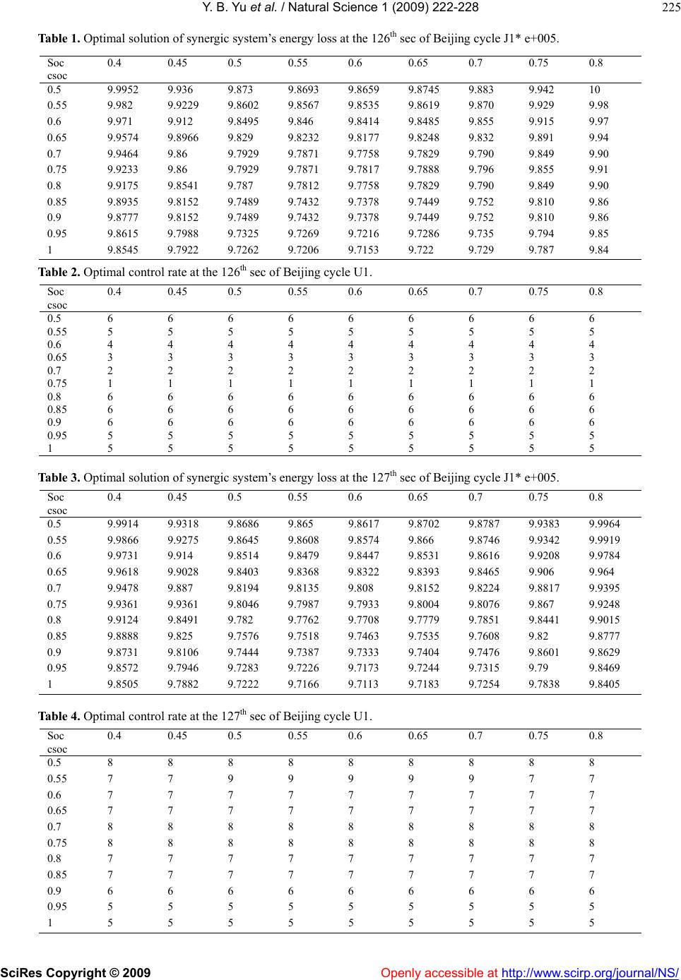 Y. B. Yu et al. / Natural Science 1 (2009) 222-228 SciRes Copyright © 2009 Openly accessible at http://www.scirp.org/journal/NS/ 225 Table 1. Optimal solution of synergic system’s energy loss at the 126th sec of Beijing cycle J1* e+005. Table 2. Optimal control rate at the 126th sec of Beijing cycle U1. Soc csoc 0.4 0.45 0.5 0.55 0.6 0.65 0.7 0.75 0.8 0.5 6 6 6 6 6 6 6 6 6 0.55 5 5 5 5 5 5 5 5 5 0.6 4 4 4 4 4 4 4 4 4 0.65 3 3 3 3 3 3 3 3 3 0.7 2 2 2 2 2 2 2 2 2 0.75 1 1 1 1 1 1 1 1 1 0.8 6 6 6 6 6 6 6 6 6 0.85 6 6 6 6 6 6 6 6 6 0.9 6 6 6 6 6 6 6 6 6 0.95 5 5 5 5 5 5 5 5 5 1 5 5 5 5 5 5 5 5 5 Table 3. Optimal solution of synergic system’s energy loss at the 127th sec of Beijing cycle J1* e+005. Soc csoc 0.4 0.45 0.5 0.55 0.6 0.65 0.7 0.75 0.8 0.5 9.9914 9.9318 9.8686 9.865 9.8617 9.8702 9.8787 9.9383 9.9964 0.55 9.9866 9.9275 9.8645 9.8608 9.8574 9.866 9.8746 9.9342 9.9919 0.6 9.9731 9.914 9.8514 9.8479 9.8447 9.8531 9.8616 9.9208 9.9784 0.65 9.9618 9.9028 9.8403 9.8368 9.8322 9.8393 9.8465 9.906 9.964 0.7 9.9478 9.887 9.8194 9.8135 9.808 9.8152 9.8224 9.8817 9.9395 0.75 9.9361 9.9361 9.8046 9.7987 9.7933 9.8004 9.8076 9.867 9.9248 0.8 9.9124 9.8491 9.782 9.7762 9.7708 9.7779 9.7851 9.8441 9.9015 0.85 9.8888 9.825 9.7576 9.7518 9.7463 9.7535 9.7608 9.82 9.8777 0.9 9.8731 9.8106 9.7444 9.7387 9.7333 9.7404 9.7476 9.8601 9.8629 0.95 9.8572 9.7946 9.7283 9.7226 9.7173 9.7244 9.7315 9.79 9.8469 1 9.8505 9.7882 9.7222 9.7166 9.7113 9.7183 9.7254 9.7838 9.8405 Table 4. Optimal control rate at the 127th sec of Beijing cycle U1. Soc csoc 0.4 0.45 0.5 0.55 0.6 0.65 0.7 0.75 0.8 0.5 8 8 8 8 8 8 8 8 8 0.55 7 7 9 9 9 9 9 7 7 0.6 7 7 7 7 7 7 7 7 7 0.65 7 7 7 7 7 7 7 7 7 0.7 8 8 8 8 8 8 8 8 8 0.75 8 8 8 8 8 8 8 8 8 0.8 7 7 7 7 7 7 7 7 7 0.85 7 7 7 7 7 7 7 7 7 0.9 6 6 6 6 6 6 6 6 6 0.95 5 5 5 5 5 5 5 5 5 1 5 5 5 5 5 5 5 5 5 Soc csoc 0.4 0.45 0.5 0.55 0.6 0.65 0.7 0.75 0.8 0.5 9.9952 9.936 9.873 9.8693 9.8659 9.8745 9.883 9.942 10 0.55 9.982 9.9229 9.8602 9.8567 9.8535 9.8619 9.870 9.929 9.98 0.6 9.971 9.912 9.8495 9.846 9.8414 9.8485 9.855 9.915 9.97 0.65 9.9574 9.8966 9.829 9.8232 9.8177 9.8248 9.832 9.891 9.94 0.7 9.9464 9.86 9.7929 9.7871 9.7758 9.7829 9.790 9.849 9.90 0.75 9.9233 9.86 9.7929 9.7871 9.7817 9.7888 9.796 9.855 9.91 0.8 9.9175 9.8541 9.787 9.7812 9.7758 9.7829 9.790 9.849 9.90 0.85 9.8935 9.8152 9.7489 9.7432 9.7378 9.7449 9.752 9.810 9.86 0.9 9.8777 9.8152 9.7489 9.7432 9.7378 9.7449 9.752 9.810 9.86 0.95 9.8615 9.7988 9.7325 9.7269 9.7216 9.7286 9.735 9.794 9.85 1 9.8545 9.7922 9.7262 9.7206 9.7153 9.722 9.729 9.787 9.84 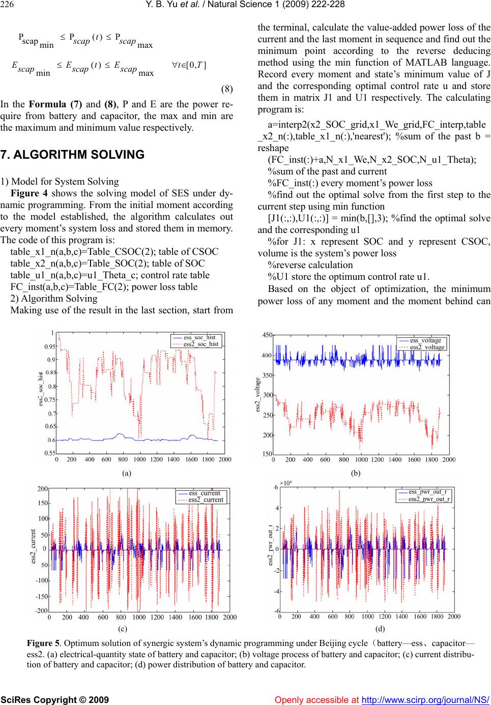 Y. B. Yu et al. / Natural Science 1 (2009) 222-228 SciRes Copyright © 2009 Openly accessible at http://www.scirp.org/journal/NS/ 226 PP()P scap min max ()[0,] min max t scap scap E EtE tT scapscap scap (8) In the Formula (7) and (8), P and E are the power re- quire from battery and capacitor, the max and min are the maximum and minimum value respectively. 7. ALGORITHM SOLVING 1) Model for System Solving Figure 4 shows the solving model of SES under dy- namic programming. From the initial moment according to the model established, the algorithm calculates out every moment’s system loss and stored them in memory. The code of this program is: table_x1_n(a,b,c)=Table_CSOC(2); table of CSOC table_x2_n(a,b,c)=Table_SOC(2); table of SOC table_u1_n(a,b,c)=u1_Theta_c; control rate table FC_inst(a,b,c)=Table_FC(2); power loss table 2) Algorithm Solving Making use of the result in the last section, start from the terminal, calculate the value-added power loss of the current and the last moment in sequence and find out the minimum point according to the reverse deducing method using the min function of MATLAB language. Record every moment and state’s minimum value of J and the corresponding optimal control rate u and store them in matrix J1 and U1 respectively. The calculating program is: a=interp2(x2_SOC_grid,x1_We_grid,FC_interp,table _x2_n(:),table_x1_n(:),'nearest'); %sum of the past b = reshape (FC_inst(:)+a,N_x1_We,N_x2_SOC,N_u1_Theta); %sum of the past and current %FC_inst(:) every moment’s power loss %find out the optimal solve from the first step to the current step using min function [J1(:,:),U1(:,:)] = min(b,[],3); %find the optimal solve and the corresponding u1 %for J1: x represent SOC and y represent CSOC, volume is the system’s power loss %reverse calculation %U1 store the optimum control rate u1. Based on the object of optimization, the minimum power loss of any moment and the moment behind can (a) (b) (c) (d) Figure 5. Optimum solution of synergic system’s dynamic programming under Beijing cycle(battery—ess、capacitor— ess2. (a) electrical-quantity state of battery and capacitor; (b) voltage process of battery and capacitor; (c) current distribu- tion of battery and capacitor; (d) power distribution of battery and capacitor.  Y. B. Yu et al. / Natural Science 1 (2009) 222-228 SciRes Copyright © 2009 Openly accessible at http://www.scirp.org/journal/NS/ 227 be calculated out under the reverse method and stored in J1. At the same time, the optimum control rate is stored in U1.Under Beijing cycle, the electrical power require- ment of the 126th sec and the 127th sec is -16859w and 37467w. Table 1 to 4 list out the optimum solve J1 and optimum control rate U1, and from which, the trend and principle of controlling can be induced. As is shown from the data, if the SOC and CSOC of battery and super capacitor at some moment are known, then the optimum solution J1 and optimum control rate U1 can be checked up from tables above. After known about the point’s power demand Pm and the optimum control rate U1, the SOC and CSOC of battery and super capacitor on the next moment can be calculated out through every parts model, and then continue to look-up tables to find out the optimum solution and optimum control rate. Followed by analogy, on the situation when the forward calculation mode. Connect every moment’s optimal control rate, the optimum control rate of SES under Beijing cycle can be drawn approximately. During calculation, if the less interval of every component’s state and control rate were used, the closer the result to the synergic system’s optimal control rate. In this way, under Beijing cycle, divide the battery’s SOC from 0.4 to 0.8 into 9 parts. The interval of each calculation point is 0.05. Divide the capacitor’s CSOC from 0.5 to 1 into 11parts to ensure that the same inter- val of calculation point is chose. After optimized calcu- lation, the optimal control rate can be counted out shown in Figure 5. Figure 5a illustrates the SOC of battery and capacitor resulted from the optimized control under Bei- jing cycle. Figure 5b shows the voltage process of bat- tery and capacitor resulted from optimum control. Figure (c&d) illustrate the current and power distribution re- sulted from the optimum control rate at every moment respectively. 3) Improved Rule-based Control Strategy The result is based on cycle, so the Dynamic Pro- gramming algorithm can be not directed applied to en- gineering control. However, some enlightening can be drawn used as the guidance of actual control algorithm programming. For example, based on the result of pre- vious section, the following four laws can be educed: a).During power assisting, if the motor required a low current, the battery would provide the power. b).During power assisting, the capacitor should provide more power when the motor is under high power demand. The two tips above are all induced by the low efficient of DC/DC under low load. c).If the capacitor is in high CSOC, and then it should share a greater proportion of discharge. However, as the CSOC drops, the discharge proportion of capacitor would diminish responsively, while battery’s proportion would increase gradually till the battery pack power the motor alone. d).When low-power braking, capacitor can recovery all the vehicle braking energy; While, with the increase of braking power, collaborative work mode of battery and capacitor would be taken by the optimized control algorithm to make the two both working on a high effi- ciency and contribute to the balance of battery. Also the proportion of discharge from capacitor would increase as the braking power increase. This is different from the rule of rule-based control strategy that energy firstly go to the capacitor and it gives inspiration for the improve- ment of control strategy. Based on the analysis above, this section proposed a modification on rule-based control strategy of SES when motor power assisting and braking energy regeneration. Details as follows: (1) When power assisting, if Pm>0,and Pm<Pset , then Pbat=Pm; (2) Otherwise, if Pm>Pset1,then Pscap=K1*Pm,but Pbat=(1- K1) *Pm;in the formula: K1 is the function of capacitor’s CSOC showed in table 5. Pset1=12.33kw. (3) When braking: if P m<0,and Pm>Pset2 , capacitor is not over recharged, then Pbat=0;otherwise when Pm<Pset2,Pscap=K2*Pm, and Pbat=(1- K2) *Pm,K2 increases as Pm decreases.Pset2=8.7kw. Figure 6 shows working process manipulate of SES’s control rate, battery and capacitor resulted from the simulation of rule-based control strategy, which is modi- fied by applied optimal algorithm. Table 6 lists com- parison of SES’s HEV simulation result under different control algorithm. Conclusions can be drawn from the various SES’s simulation results listed in the table, that HEV vehicle have optimum fuel economy under control of dynamic programming algorithm. Using the principle of optimized DP algorithm, designer could know the maximum energy-saving efficient contributed by SES and also could compile optimal control algorithm of SES, which can be used in actual engineering. Under this cir- Table 5. Relationship between Ki and CSOC. CSOC0.5 0.6 0.7 0.8 0.9 1.0 K1 0 0.2 0.4 0.6 0.8 1.0 Table 6. Simulation result comparison of synergic system. Control strategyRule-based Dynamic programming Improved rule-based Fuel economy (L/100km) 25.7 23.2 24.5 Fuel economy improvement 1 ↑2.1% ↑1.6% Power effi- ciency 87% 93% 91% Brake energy recovery effi- cient 8.34% 9.74% 9.35%  Y. B. Yu et al. / Natural Science 1 (2009) 222-228 SciRes Copyright © 2009 http://www.scirp.org/journal/NS/ 228 Openly accessible at (a) (b) Figure 6. Simulation result based on the optimized rule-based control strategy under Beijing cycle; (a) SOC,current and voltage of battery; (b) CSOC, current and voltage of capacitor. cumstance,capacitor can keep appropriate power state at anytime and make vehicle fuel consumption a further reduction. All the advantages above can prove the sig- nificance improvement by dynamic programming opti- mization algorithm 8. CONCLUSIONS 1) Dynamic programming algorithm had been applied to SES to find out the optimum control rate using off-line simulation. 2) Rule-based control algorithm was established based on the optimum control rate. The simulation results demonstrated that the method is practical and effective. 3) Based on the control rules of overall optimized al- gorithm, the rule-based control strategy of the SES had been improved and the control effect had also been evaluated. The dissertation explicated the best perform- ance and most efficient control method of SES which could make the best contribution to vehicle energy-saving. 4) The overall optimized principle was suitable for the programming and optimizing of control algorithm for HEV vehicle with multi-energy power source. REFERENCES [1] T. Markel, M. Zolot, K. B. Wipke, and A. A. Pesaran, (2003) Energy storage system requirement for hybrid fuel cell vehicles. Advanced Automotive Battery Con- ference, Nice, France, June. 10-13. [2] A. C. Baisden and A. Emadi, (2004) ADVISOR-based model of a battery and an ultra capacitor energy source for hybrid vehicles. IEEE Transactions on Vehicular Technology, 53(1). [3] Y. B. Yu and Q. N. Wang, (2005) The redevelopment of synergy electric power HEV simulation software based on advisor. Jilin Daxue Xuebao (Gongxueban) /Journal of Jilin University (Engineering and Technology Edition), 35(4), 353-357. [4] Y. B. Yu and W. H. Wang, (2007) The research on fuzzy logic control strategy of synergic electric system of hy- brid electric vehicle. SAE Internatioal, 07APAC-185. [5] D. P. Bertsekas, (1995) Dynamic programming and op- timal control, Athena Scientific. [6] J. M. Kang, I. Kolmanovsky, and J. W. Grizzle, (1999) Approximate dynamic programming solutions for lean burn engine aftertreatment. proceedings of the IEEE conference on decision and control, 2, Piscataway, NJ, 1703-1708. [7] C. Lin, J. Kang, J. W. Grizzle, and H. Peng, (2001) En- ergy management strategy for a parallel hybrid electric truck. Proceedings of the 2001 American Control Con- ference, Arlington, VA, 2878-2883. [8] M. P. O’Keefe and T. Markel, (2006) Dynamic pro- gramming applied to investigate energy management strategies for a plug-in HEV. The 22nd International Bat- tery, Hybrid and Fuel Cell Electric Vehicle Symposium and Exhibition (EVS-22), Yokohama, Japan, October 23–28. [9] L. V. P´erez and G. R. Bossio, (2006) Optimization of power management in an hybrid electric vehicle using dynamic programming. Mathematics and Computers in Simulation, 73, 244–254. |