Engineering
Vol.06 No.13(2014), Article ID:52681,15 pages
10.4236/eng.2014.613088
Simultaneous Multimode Oscillation of Stress-Compensated Cut Quartz Resonator with Narrow-Band Wide Variable-Range Quartz Crystal Oscillator
Tomio Sato, Tetsuya Akitsu
Division of Human Environmental and Medical Engineering, Interdisciplinary Graduate School of Medicine and Engineering, University of Yamanashi, Kofu, Japan
Email: akitsu@yamanashi.ac.jp
Academic Editor: Yongdong Li, Department of Mechanical Engineering, Academy of Armored Force Engineering, China
Copyright © 2014 by authors and Scientific Research Publishing Inc.
This work is licensed under the Creative Commons Attribution International License (CC BY).
http://creativecommons.org/licenses/by/4.0/


Received 16 September 2014; revised 12 October 2014; accepted 5 November 2014
ABSTRACT
A multimode-quartz-crystal oscillator was developed to excite stable dual-mode resonance at different frequencies: The oscillation of the 3rd harmonic resonance of the principle C-mode and an additional resonance B-mode of SC-cut crystal. Harmonic combinations of the 3rd and fundamental mode of B-mode with the 3rd harmonics of C-mode are demonstrated. The measurement of the temperature dependence of the oscillation frequency is demonstrated along with the stability determined by root Allan variance. Dependence on the open conductance of the active circuit and the dependence on the coupling capacitors are discussed.
Keywords:
Temperature Sensing, Piezoelectric Sensor, Dual-Mode Quartz Crystal Resonance, Stress-Compensated Cut (SC-Cut)

1. Introduction
Piezoelectric sensing is increasingly attracting attentions, employing frequency-based measurement depending on the surface loading, mass, and a variety of force acting on the piezoelectric resonator. The quartz crystal resonator determines a stable electrical resonance frequency corresponding to the mechanical resonance frequency. The quartz crystal resonator shows a variety of resonance modes. For example, in an AT-cut quartz crystal, the harmonic combination of the different temperature characteristics of the fundamental, 3rd and 5th harmonic resonances of provides a high precision thermometric system. In the past history, dual-mode oscillation was attempted by several groups and is reviewed in References [1] -[6] . In Reference [3] , a thermometry method is presented, using a harmonically related pair of C-modes of an SC-cut quartz crystal resonator. SC cut is pro- duced with a double rotated cut angle. One of the benefits of SC cut application is stress compensation, which can provide a solution for the temperature shock sensitivity and multimode oscillation: providing primary mode oscillation with high stability called C-mode and additional resonance B-mode located at 9% higher frequency. The experiment is realized by the combination of oscillation circuit with passive frequency discrimination cir- cuits or heterodyne method observing a mixed signal response of the quartz crystal resonator. Simultaneous multimode observation in the crystal provides larger information, because this mode acts as an embedded ther- mometer having a frequency shift proportional to temperature, which in turn enables precise control of the tem- perature stabilizing the oscillation frequency and precise control of the oscillation frequency and the stability. Recently, we described the development of a narrow-band quartz crystal oscillator circuit [7] . C-mode is aimed as a stable frequency standard and B-mode is aimed as a thermometry method. The dual-mode quartz crystal oscillator in the combination of the 3rd harmonics oscillations of C-mode and the 3rd harmonics of B-mode needs the discrimination of narrower frequency separation, compared with the combination of the fundamental oscillation of B-mode. In this work, stable dual-mode quartz crystal oscillator circuit was developed based on a combination of two identical narrow gain quartz crystal oscillators. Measurement of frequency stability is based on the Allan deviation for discrete multiple measure determined following Barnes et al. [8] and Allan [9] . The Allan deviation in the simultaneous dual-mode oscillation and the oscillation condition for multiple oscillation modes are presented following IEEE Standard 1139 [10] .
2. Dual Mode Quartz Crystal Oscillator
2.1. Analysis of Dual Mode Quartz Crystal Oscillator
Figure 1 shows the dual-mode oscillation circuit. Individual oscillator circuits are developed from a narrow- band, double-resonance quartz crystal oscillator [7] .

Figure 1. Dual mode quartz crystal oscillator.
Local resonance circuits consist of L02 and C0x, L12 and C1x. C0y and C1y are inserted to the connection to a crystal resonator. Feedback resistors R02, R03, R12, and R13 are inserted into the power line between CMOS inverter integrated circuits IC1 and IC2 and ground aimed at suppression of current and gain control. C05, C06, C15, and C16 are pass capacitors. C02, C03, C12, and C13 are necessary for the generation of negative resistance. This circuit synthesizes LC oscillation mode determined by L02 and combined capacitors C0x, C02, C03, and C0y, and LC oscillation mode determined by L12 and combined capacitors C1x, C12, C13, and C1y. The oscillation frequency is settled in the vicinity of the quartz crystal oscillation frequency. Coupling capacitors C04 and C14 are omitted in the following analysis. Coupling capacitors C0y and C1y are connected to the quartz crystal resonator. Appropriate choice of the local resonance circuit and the coupling capacitors are necessary to realize stable dual-mode quartz crystal oscillation. Two oscillator circuits OSC1 and OSC2 are connected to the resonator by capacitors C0y and C1y. The SC-cut quartz crystal resonator shows C-mode a primary oscillation mode with good stability, and B-mode, a side mode, linearly proportional to the change of ambient temperature. CMOS Inverters IC1 and IC2 are replaced with a constant current source. In the equivalent circuit on the left side is OSC1 and on the right side is OSC2. Iout1 and Iout2 are output current, and Vin1 and Vin2 are input voltage of each inverter: r02 and r12 are internal resistance of inductance L02 and L12, respectively. C0s and C1s are stray capacitance parallel to capacitance C0x and C1s. Impedance Z01 consists of L02, r02, C0x, and C0s, similarly, impedance of the circuit Z11 which consists of L12, r12, C1x, and C1s, and Zxt for the parallel circuit of a quartz resonator and Cp, reduced impedance is found. Capacitance of leads and connected lines on the circuit board are modeled by Cp. Applying Kirchhoff’s law, homogeneous Equation (1) is found.
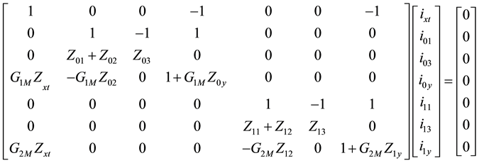 (1)
(1)
The open conductance Gm is adjusted by negative feedback resistors R02, R03, R12, and R13. Equivalent trans- conductance is defined by the open conductance and a feedback resistance, as in (2).
 (2)
(2)
The open conductance of the CMOS inverter is expressed with drain current Id and conductance coefficient K defined in the terms of electron and hole mobility μ and the unit gap capacitance Cg. W/L is the ratio of width over length of the gate:

Feedback resistance:

Solving the determinant of the coefficient matrix, relation (3) is found. The second term on the left side of this relation indicates the impedance of OSC1, and the third term indicates the impedance of OSC2. The impedance of individual oscillator is connected in parallel to Zxt.
 (3)
(3)
Figure 2 shows the entire structure of the oscillator equivalent circuit-2, indicating the impedance of OSC1 as Z1 and the impedance of OSC2 as Z2, R1, R2, C1, and C2 are equivalent resistance and capacitance of the imped-

Figure 2. Equivalent circuit-2.
ance. R1, C1, Ra, La, C0xs, ω0x, ω0s, and ω1 are found in (4). R2, C2, Rb, Lb, C1xs, ω1x, ω1s, and ω2 are found in (5).

 (4)
(4)


Similarly,
 (5)
(5)
where


Including the equivalent circuit of Zxt, equivalent circuit-3 is found in Figure 3, where L1, C1, and R1 are the motion arm and C0 is the parallel capacitance. Cp is stray capacitance on the circuit board connected to the reso- nator. Solving for Zxt, equivalent resistance Rci and equivalent reactance Cci of parallel connection of Z1 and Z2

Figure 3. Equivalent circuit-3.
are found.

where
 (6)
(6)
Figure 4 shows a simplified graphical expression of equivalent circuit-4, where capacitance C0p consists of C0 and Cp, and Ccci consists of Cci and Cz. The whole circuit consists of elements C0, L1, C1, and R1 representing the equivalent circuit of the selected mode of the SC-cut quartz crystal resonator (values are in Table 1).
Including C0, Cp and Cz into Cci and Rci composed equivalent impedance Ccci and Rcci are found, as in (7).
 (7)
(7)
Supposing i(ω) in the closed circuit of this diagram, the resistance condition is found from the matching condition for the real part where the real part is equal to zero. Oscillation frequency is determined from the matching condition of the capacitance, where the imaginary part is equal to zero.
2.2. Oscillation Conditions: Combination of Fundamental Resonance and the 3rd Harmonics
Oscillation conditions are given as the resistance condition and frequency condition, in the following forms (8) and (9), respectively:
 (8)
(8)
 (9)
(9)

Figure 4. Equivalent circuit-4.

Table 1. Equivalent circuit constant of the SC cut quartz crystal resonator.
Inequality in condition (8) indicates that the negative resistance larger than damping is necessary at the beginning of oscillation. The series resonance frequency f1 is determined by L1 and C1 determined in relation (10), where ω1 is angular frequency and fr is the series resonance frequency.
 (10)
(10)
The resistance condition is estimated for the oscillation of each mode from Table 1, the value of series resistance R1c and R1b determined by the impedance analyzer. Relation (11) shows resistance conditions for the 3rd harmonic resonance modes. The frequency condition shows the resonance frequency determined by L1c and C1c or L1b and C1b. C1c and C1b are extremely smaller than Ccci.
 (11)
(11)
In the case of the fundamental resonance of B-mode, the series resistance is reduced to 61.77Ω. Negative resistance of the active circuit is indicated by the absolute value. In the physical meaning, this value balances with the damping; this value is expressed in the following form:

Figure 5 shows the tuning characteristics by changing resonator capacitors C0x and C1x combined with L02 and L12, which determine the oscillation frequency of the individual oscillation mode.
The frequency dependence of negative resistance is tailored considering the influence of resonator capacitors C0x and C1x. The oscillation condition of the 3rd harmonics of C-mode is fulfilled at C1x = 20.5 pF, where the oscillation frequency is close to the series resonance frequency. The maximum absolute value of negative resistance is approximately 1.99 kΩ, at 9.992 MHz. The frequency range varies from 0.28 to 0.3 MHz. Similarly, the oscillation condition of the 3rd harmonics B-mode is fulfilled at C0x = 13.5 pF, close to the series resonance frequency f1b. The maximum absolute value of negative resistance is approximately 1.9 kΩ, at 10.9 MHz. The oscillation condition is fulfilled from 10.84 to 10.96 MHz. The frequency range varies from 0.11 to 0.12 MHz. In the combination of the fundamental oscillation of B-mode and the 3rd harmonic resonance of C-mode, the dual mode oscillation is realized at C0x = 31 pF and C1x = 20.5 pF.
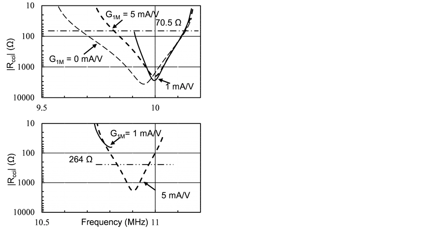
In the combination of the 3rd harmonic resonance modes, the multimode-oscillation is observed provided that the oscillation condition is fulfilled simultaneously. In the stable oscillation, gain G1M decreases compared with

Figure 5. Frequency dependence of negative resistance for local resonator capacitors: C0x and C1x.
the initial phase. At G1M = 1 mA/V, the damping resistance becomes larger than negative resistance. The maximum absolute value of negative resistance is approximately equal to 2 kΩ and the damping resistance of the 3rd harmonic resonance of B-mode is 264 Ω. The negative resistance of the oscillator is shown for various values of gain G1M, in the vicinity of 10.9 MHz and 10 MHz.
In Figure 6(a) and Figure 6(b), as the gain decreases in the stable oscillation at G1M = 1 mA/V, the negative resistance becomes smaller than R1b then the oscillation condition is no longer fulfilled, while the oscillation condition for C-mode still holds. Transition of oscillation mode occurs from dual-mode oscillation to the single oscillation. Figure 6(c) and Figure 6(d) shows the oscillation condition the gain of C-mode oscillator G2M. G2M is settled to 5 mA/V initially, and the gain of the counterpart oscillator B-mode oscillator G1M is settled to 5 mA/V. The maximum absolute value of negative resistance is approximately 2 kΩ. Generally, the transconductance GM of the oscillator circuit decreases in the magnitude on the growth of signals, and the frequency dependence of negative resistance varies depending on GM. In the case where G1M of OSC1 is equal to 0 mA/V, negative resistance of OSC2 shows wide-frequency characteristics and decreases in the frequency according to the increase in the magnitude of G1M. Negative resistance of OSC1 shows an abrupt change in the vicinity of G1M = 1 mA/V. Negative resistance of OSC2 shows corresponding change but the oscillation condition is fulfilled. Similar tendency is observed in the dependence of negative resistance of OSC1 according to the decrease in conductance G2M of OSC2.
The gain at the initial stage of oscillation is set at 5 mA/V, along with the growth of the signal, B-mode shows a maximum value of negative resistance 4.5 kΩ at G1M of approximately 2 mA/V, then steeply decreases. In Figure 7(a), negative resistance shows zero at G1M approximately 1.8 mA/V. As the negative resistance of C- mode is larger than 1 kΩ, a maximum value 3.4 kΩ is observed at G1M approximately 0.5 mA/V, the oscillation condition is fulfilled for this mode, and the oscillation mode transfers to C-mode and B-mode becomes incapable. Similarly in Figure 7(b), the gain settled to 5 mA/V at the initial stage of oscillation, and the negative resistance shows zero at G2M approximately 1.0 mA/V. As the negative resistance of B-mode is larger than 0.7 kΩ, a maximum 4.7 kΩ at G1M of 1.3 mA/V, the oscillation mode transfers to the single mode oscillation of B-mode when the condition of C-mode becomes unfulfilled. When the 3rd harmonic resonance of B-mode is selected, the resistance is 264 Ω, and the oscillation region becomes narrower, because larger negative resistance is needed due to the dependence on G1M. Because the dependence on G2M is fulfilled, the oscillation region is limited by the the B-mode oscillator. Figure 7(c) and Figure 7(d) show the case of the combination of B-mode fundamental versus the 3rd harmonics of C-mode. In this case, the series resistance of B-mode decreases to 61.77 Ω.
Figure 8 shows the dependence on the transconductance for the case two parameters are varied simultaneously. Initially, gain G1M and G2M are settled to 5 mA/V. When the gain G1M decreases to 2.6 mA/V, negative resistance for B-mode shows 4.8 kΩ. Then it shows a maximum value 0 Ω at G1M = 2.1 mA/V. Similarly, C-mode shows 2.9 kΩ, at G2M = 1.8 mA/V. Then, it shows a maximum 0 Ω at G1M = 1.15 mA/V. The maximum value of negative resistance is located at a certain value of gain, which is not necessarily large. In another view of the oscillation conditions, quartz crystal oscillation is stabilized at minimum negative resistance. The minimum value of negative resistance |Rcci|min is 264 Ω for B-mode and 70.5 Ω for C-mode, from Table 1. At |Rcci|min larger than
 (a) (b)
 (c) (d)
Figure 6. Depencence of negative resistance on transconductance: G1M and G2M. (a) Negative resistance in the combination of the 3rd harmonics B-mode vs. 3rd C-mode; (b) Negative resistance in the combination of B-mode fundamental vs. the 3rd harmonics C-mode; (c) Negative resistance in the combination of the 3rd harmonics B-mode vs. 3rd C-mode; (d) Negative resistance in the combination of B-mode fundamental vs. the 3rd harmonics C-mode.
70.5 Ω the oscillation condition of C-mode is fulfilled before the oscillation condition of B-mode is achieved, if negative resistance is smaller than 264 Ω. In this case, the oscillation mode transfers to the single oscillation of C-mode.
Figure 9 shows the dependence of negative resistance on frequency for various values of coupling capacitors: C0y and C1y.
In Figure 9(a), the case of the combination of the 3rd harmonic resonance of B-mode and C-mode, C0y is

 (a) (b)
 (c) (d)
Figure 7. Dependence of negative resistance on gain: G1M and G2M. (a) Dependence on G1M, G2M = 5 mA/V; (b) Dependence on G2M, G1M = 5 mA/V; (c) Dependence on G1M, G2M = 5 mA/V; (d) Dependence on G2M, G1M = 5 mA/V.

 (a) (b)
Figure 8. Dependence of negative resistance on gain: G1M and G2M. (a) Combination of the 3rd harmonics of B-mode versus 3rd harmonics of C-mode; (b) Combination of the fundamental of B-mode versus 3rd harmonics of C-mode.
fixed at 10 pF. The case of C0y = 0 pF means that the oscillator is disconnected from the quartz resonator and only OSC1 is connected to the resonator. The oscillation condition for B-mode (OSC1) is fulfilled in a narrow region in the vicinity of the resonance frequency, in the case where C1y = 30 pF:

In Figure 9(b), the case of the combination of the fundamental B-mode versus the 3rd harmonics of C-mode, C1y is fixed at 10 pF. The case C0y = 0 pF means that OSC1 (B-mode) is disconnected and only OSC2 (C-mode) is connected with the quartz resonator. The oscillation condition for C-mode is fulfilled from 9.7 to 10.1 MHz. For C0y = 10 pF, the negative resistance of OSC1 and OSC2 is approximately equal to 2 kΩ. The oscillation con-

 (a) (b)
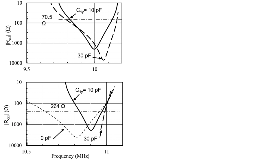
 (c) (d)
Figure 9. Dependence of negative resistance on coupling capacitors: C0y and C1y. (a) Combination of the 3rd harmonics of B-mode versus the 3rd harmonics of C-mode. C1y is fixed at 10 pF; (b) Combination of B-mode fundamental versus the 3rd harmonics of C-mode. G1M = 5 mA/V and G2M = 5 mA/V; Cz = ∞ pF; (c) Combination of the 3rd harmonics of B-mode versus the 3rd harmonics of C-mode. C0x = 13.5 pF; C0s = 5 pF; C0y = 10 pF; (d) Combination of fundamental B-mode versus the 3rd harmonics of C-mode. C0x = 31 pF; C1x = 20.5 pF; C1s = 5 pF; L12 = 5.6 μH; G2M = 5 mA/V; Cp = 2 pF; C0c = 3.431 pF; C0b = 3.244 pF.
dition for C-mode is fulfilled from 9.8 to 10.1 MHz and for B-mode from 10.8 to 10.9 MHz. If C0y is set to 30 pF, the oscillation condition for OSC2 is fulfilled, but the negative resistance for OSC1 is lower than the critical value. Figure 9(c) and Figure 9(d) show the oscillation condition for OSC2. C1y is varied while the counterpart C0y is fixed at 10 pF. The peak for the OSC2 steps out of the resonance frequency region at C1y equal to or larger than 30 pF.
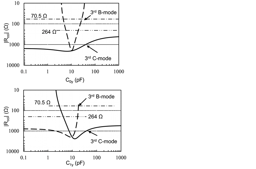
Figure 10 shows negative resistance as functions of coupling capacitors C0y and C1y, where C0y either C1y is variable and counterpart is fixed at 10 pF. C1y = 10 pF, the oscillation condition of B-mode is fulfilled from 3.56 to 3.8 MHz, and the oscillation condition of C-mode is fulfilled from 9.8 to 10.1 MHz. The relation between negative resistance |Rcci| and coupling capacitor C0y shows that negative resistance of C-mode oscillator fulfills the oscillation condition for wide range of C0y.

On the other hand, negative resistance of the B-mode oscillator fulfills the oscillation condition only in a narrower region from 6 to 18 pF.

The oscillation condition of C-mode is fulfilled, at C0y and C1y from 2 to 48 pF, and stable oscillation of C-mode is available. The oscillation condition of B-mode is fulfilled only at narrower region of C0y and C1y from 6 to 13 pF. Stable dual mode resonance oscillation is available in this region. Figure 10(b) shows the case of the combination of fundamental B-mode and the 3rd harmonics of C-mode. The oscillation condition is fulfilled in wider choice of the parameter C0y and C1y. The value of connecting capacitors C0y and C1y is a parameter that enables simultaneous dual mode resonance oscillation. In summary, the best coupling capacitances are C0y = 10 pF and C1y = 10 pF. If C0y is larger than 30 pF, the oscillation condition for OSC1 is not fulfilled, while the oscillation condition for OSC2 is fulfilled from 9.8 to 10.2 MHz. This discussion on the choice of coupling capacitors must be reviewed in the case of the lower limit of the transconductance.
 (a) (b)
Figure 10. Dependence of negative resistance on coupling capacitors: C0y and C1. (a) Combination of the 3rd harmonics of C-mode and B-mode; (b) Combination of the fundamental B-mode and the 3rd harmonics of C-mode.
3. Experimental Result and Discussions
3.1. Analysis of the Stability
The short-time stability of the C-mode oscillation is compared. The bottom level of the σ versus τ dependence is employed as the measure of the stability, where σ is the root Allan variance defined as (12) and τ is the sampling interval (gate time) [10]
 (12)
(12)
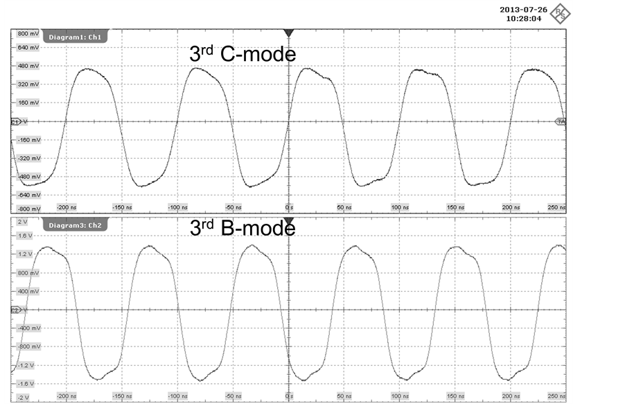
fk is the moving average of 10 sequential of frequency data. τ is the sampling time interval. M is the number of samples per measurement. The average of frequency is calculated over the gate time. Measurement was carried out by universal frequency counters Agilent 53230A (Agilent Technologies, Santa Clara, Ca, USA) synchronized with a rubidium oscillator. Figure 11 shows typical example of wave forms observed in the simultaneous multimode oscillation.
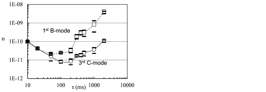
The stability of the single C-mode oscillation is compared with the simultaneous multimode oscillation of different harmonic combinations. In this experiment, the measure of the stability is the bottom level of the σ versus τ dependence, where σ is the root Allan variance defined as (12) and τ is the sampling interval (gate time). Figure 12 shows the σ versus τ curve for the oscillation of C-mode, single-mode oscillation.
Figure 13(a) shows the root Allan variance of the 3rd harmonics of C-mode σy(τ) < 10−10 at τ of 100 - 1000 ms and the 3rd harmonics of B-mode σy(τ) < 10−10 for the gate time below 500 ms. Figure 13(b) shows the 3rd harmonics of C-mode shows σy(τ) < 10−10 for τ from 20 to 1000 ms, and the fundamental B-mode σy(τ) < 10−10 for τ from 20 to 1000 ms, indicating high stability of the simultaneous multimode oscillation comparable to the single mode oscillation.
3.2. Temperature Dependence of Oscillation Frequency
Temperature dependence of the oscillation frequency was measured in the simultaneous oscillation. Allan standard deviation was observed to avoid spontaneous mode change of additional resonance mode. Figure 14 shows root Allan variance at the start point and at higher end of the temperature range. Figure 15 shows the temperature dependence of the oscillation frequency observed simultaneously.
The regression curve of C-mode shows a cubic function with an inflection point at 85.7˚C (Designed value). The frequency drift of C-mode is 0.32 × 10⁻⁶ per degree Celsius. This result suggests that the stability of the oscillator remains at the level of typical quartz crystal oscillator. The regression curve of B-mode indicates a linear dependence of approximately −26.5 ppm/degree. The dual-mode oscillation direct thermometry is applicable over this temperature range.
3.3. Suppression of the Fundamental B-Mode Oscillations
Figure 16 shows a typical example of the spectrum of the dual mode quartz crystal oscillation. The spectrum was measured by real time FFT analysis (Rohde-Schwarz RT1004, Rhode and Schwarz Company, Munich, Germany).
Figure 16(a) shows the combination of the 3rd harmonics of C-mode and B-mode, and Figure 16(b) shows the case of the combination of the 3rd harmonics of C-mode and fundamental B-mode. Compared with the separation of frequency between the 3rd harmonics, the separation between the 3rd harmonics oscillation of C-mode and fundamental oscillation of B-mode is 6.2 MHz. This wide separation enables easier construction of the mode discrimination system, but this scheme results in more numbers of spectral peaks.
The common part of circuit constants for the analysis are as follows: Oscillator 1: C02 and C03 = 47 pF; C0s = 5 pF; C0y = 10 pF; G1M = 5 mA/V. Circuit constant of Oscillator 2: C12 and C13 = 47 pF; C1s = 5 pF; C1y = 10 pF; G2M = 5 mA/V; Cz = 100 pF; Cp = 2 pF; C0c = 3.431 pF; C0b = 3.244 pF. L02 = 5.6 μH; L12 = 5.6 μH; C0x = 9 pF; C1x = 17 pF; L02 = 33 μH for the fundamental mode or L02 = 5.6 μH for the 3rd harmonic resonance of B-mode.
The common part of circuit constants for this experimental part is as follows. Oscillator 1: C02 and C03 = 47 pF; C0y = 10 pF; L02 = 5.6 μH; C0x = 9 pF for the 3rd harmonic resonance and L02 = 33 μH; C0x = 30 pF for the
 (a)
(a) (b)
(b)
Figure 11. Observation of simultaneous dual-mode oscillation of SC-cut quartz crystal resonator. (a) Upper track: C-mode 3rd harmonics, 9.999331 MHz. Lower track: B-mode 3rd harmonics, 10.885515 MHz. Horizontal scale: 100 ns/div; (b) Upper track: C-mode, 3rd harmonics, 9.999733 MHz, Lower track: B-mode, fundamental, 3.691164 MHz. Horizontal scale: 200 ns/div.

Figure 12. σ versus τ curve of single mode oscillation of C- mode. Open circles: C-mode (9.999835 MHz).

 (a) (b)
Figure 13. σ versus τ curve of simultaneous dual-mode oscillation. Open circles: C-mode. Open square symbols: B-mode. Bars: Standard deviation of 5 sequential measurement. (a) σ versus τ curve of C-mode (3rd harmonics, 9.999331 MHz), B-mode (3rd harmonics, 10.885515 MHz); (b) σ versus τ curve of C-mode at (3rd harmonics, 9.999733 MHz), B-mode (fundamental, 3.691164 MHz).

 (a) (b)
Figure 14. σ versus τ curve at the start and the endpoint of the temperature dependence. Open circles: C-mode. Open square symboles: B-mode. Bar: Standard deviation of 5 sequential data. (a) σ versus τ curve of C-mode (3rd harmonics, 9.999331 MHz), B-mode (3rd harmonics, 10.885515 MHz) at 27˚C; (b) σ versus τ curve of C-mode (3rd harmonics, 9.9999956 MHz), B-mode (3rd harmonics, 10.963845 MHz) at 80˚C.

Figure 15. Simultaneously measured oscillation frequency. Open circles: C-mode. Open square symbols: B-mode. Regres- sion function of B-mode: Y = −26.453X + 716.55.
 (a)
(a)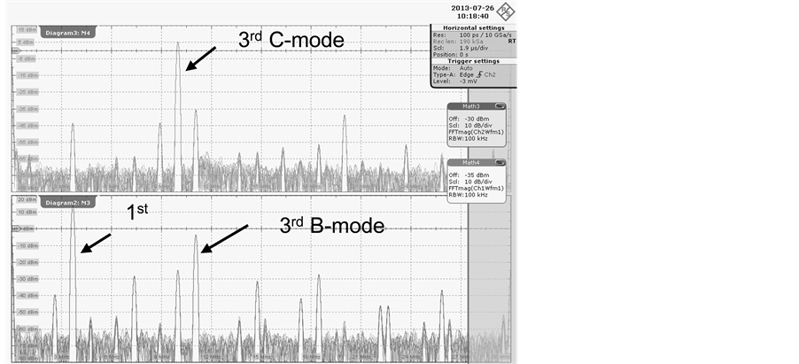 (b)
(b)
Figure 16. Spectrum of the simultaneous oscillation. Horizontal scale: Span 0 to 30 MHz. Resolution 100 kHz. (a) Spectrum of C-mode (3rd harmonics, 9.99975 MHz upper track) and B-mode (3rd harmonics, 10.97758 MHz lower track); (b) Spectrum of C-mode (3rd harmonics, 9.99975 MHz, upper track) and B-mode (fundamental, 3.69147 MHz, lower track).
fundamental resonance of B-mode. Oscillator 2: C12 and C13 = 47 pF; C1y = 10 pF; L12 = 5.6 μH; C1x = 17 pF for the 3rd harmonic resonance of C-mode. IC1 and IC2 TC7SHU04F, Vcc = 5 V.
4. Conclusions
The SC-cut resonator is made of double-rotated cut crystals and it shows a principal resonance C-mode and B-mode, additional resonance mode. High stability of the principal mode was observed in both single and multimode resonance oscillation. The linear dependence of the B-mode on the temperature can realized the thermometric method with the assurances of the stability. Design rules were ensured by the measurement of the stability of σ versus τ curve.
The narrow-band wide variable crystal oscillator circuit was proved to be an efficient experimental maneuver in the simultaneous measurement of the stability and the oscillation frequency dependence on the ambient temperature. The frequency separation is narrower than the combination of the 3rd harmonic resonance of C-mode and the fundamental resonance of B-mode which is approximately 6.2 MHz. The combination of the 3rd harmonic resonance oscillation shows quasi-sinusoidal wave forms with negligible distortion with Allan standard deviation σy(τ), 10−11 < σy(τ) < 10−10, sufficiently stable for standard time base and sensor applications. In the present stage of the experiment, the demonstrated result was obtained by precise choice of the circuit constant and bias current. It is necessary to monitor the unlocking from crystal resonance by the real-time monitoring of the Allan standard deviation. Although the reproducibility of the circuit and the oscillation condition is not thoroughly identified and appropriate circuit design is still necessary, we risk concluding that the dual-mode quartz crystal resonance oscillation can be applied to piezoelectric sensing and the production of a stable frequency standard.
Acknowledgements
We express acknowledgement to Ms Ruzaini Izyan binti Ruslan and Ms Izzati Syazwani binti Othman for their collaboration in the early stage of experiment, and Mr. Masahide Marumo, River Eletec Company (Japan) for fruitful discussions.
References
- Vig, J.R. (1999) Dual-Mode Oscillators for Clocks and Sensors. Proceedings of the 1999 IEEE Ultrasonics Symposium, Caesars Tahoe, 17-20 October 1999, 859-868. http://dx.doi.org/10.1109/ULTSYM.1999.849128
- Vig, J.R. (2001) Temperature Insensitive Dual-Mode-Resonant Sensors―A Review. IEEE Sensors Journal, 1, 62-68. http://dx.doi.org/10.1109/JSEN.2001.923588
- Schodowski, S.S. (1989) Resonator Self-Temperature Sensing Using a Dual-Harmonic-Mode Oscillator. Proceedings of the 43rd Annual Symposium on Frequency Control, Denver, 31 May-2 June 1989, 2-7. http://dx.doi.org/10.1109/FREQ.1989.68851
- Vig, J.R. (2012) Thermometric Beat Frequency Generation. In: Quartz Crystal Resonators and Oscillators for Frequency Control and Timing Applications. A Tutorial, US Army, Communications Electronics Research Development & Engineering Center (CERDEC), Fort Monmouth, 65-71. http://www.ieee-uffc.org/frequency_control/teaching/vig/vig3.ppt-2012-05-14
- Štofanik, V., Baláž, I., Minárik, M. and Cocherová, E. (2008) Investigation of Self-Temperature-Sensing of SC-Cut with Simultaneous Excitation of Two Higher Overtones in Dual-Mode Crystal Oscillator. IEEE International Frequency Control Symposium, Honolulu, 19-21 May 2008, 170-173.
- Ferrari, M., Ferrari, V. and Kanazawa, K.K. (2008) Dual Harmonic Oscillator for Quartz Crystal Resonator Sensors. Sen- sors and Actuators A, 145-146, 131-138.
- Izyan-Ruslan, R., Sato, T. and Akitsu, T. (2012) Voltage Controlled Narrow Band Wide-Variable Range Four Segment Quartz Crystal Oscillator. Transactions Ultrasonics, Ferro-Electrics and Frequency Control, 59, 564-572.
- Barnes, J.A., Chi, A.R., Cutler, L.S., Healey, D.J., Leeson, D.B., McGunigal, T.E., Mullen Jr., J.A., Smith, W.L., Sydnor, R.L., Vessot, R.F.C. and Winkler, G.M.R. (1971) Characterization of Frequency Stability. IEEE Transactions on Instrumentation and Measurement, IM-20, 105-120.
- Allan, D.W. (1966) Statistics of Atomic Frequency Standards. Proceedings of the IEEE, 54, 221-230. http://dx.doi.org/10.1109/PROC.1966.4634
- 1139-1999 IEEE Standard Definitions of Physical Quantities for Fundamental Frequency and Time Metrology.