Engineering
Vol. 4 No. 10 (2012) , Article ID: 23354 , 4 pages DOI:10.4236/eng.2012.410085
CFD Simulation of Scale Influence on the Hydrodynamics of an Internal Loop Airlift Reactor
Department of Chemical Engineering, Faculty of Engineering, Arak University, Arak, Iran
Email: *R-Davarnejad@araku.ac.ir
Received July 12, 2012; revised August 14, 2012; accepted August 25, 2012
Keywords: Internal Loop Airlift Reactor; Gas Hold-Up; CFD
ABSTRACT
In this work, the overall gas hold-up in the riser and down-comer of three internal airlift reactors with a working volume of 10.5, 32 and 200 l at the range of temperatures 18˚C - 21˚C, under atmospheric pressure was simulated using Computational Fluid Dynamics (CFD). The range of superficial gas velocity was 0.5 - 3 cm/s. The three reactors geometrically were similar to each other. CFD simulation and experimental data showed that the gas hold-up in the riser and down-comer increased by increasing the reactor scale. It was concluded that the simulated data were in good agreement with the experimental ones obtained from the literature.
1. Introduction
Liquid circulation velocity and gas hold-up are the major hydrodynamic parameters and their knowledge is essential for a reliable description of an airlift reactor with internal loop [1]. Internal loop airlift reactors are widely used in biochemical industrial processes because of their simple construction, good heat transfer, low shear rate, low power input and easy scale up [2]. An internal loop airlift reactor is divided into two zones: riser and downcomer zone. There is a vertical baffle between of them and a sparger in bottom of the riser zone. The difference of density between liquid and gas makes the liquid circulation [3]. Recently, many authors have attempted to employ the airlift reactors for organic compounds production [4,5] and wastewater treatment [6]. Internal airlift reactor is the best type of two phase contactors at various aeration processes such as wastewater treatment, animal cell culture and aerobic fermentation (production of enzymes, antibiotics, proteins, biomass and other biotechnology products) [7,8]. Trager et al. used a simple laboratory airlift reactor (fermentor) to produce gluconic acid by Aspergillusniger [9]. Park et al. used an airlift bioreactor in which the top and bottom of the draft tubes were covered with stainless steel sieves for the production of itaconic acid by Aspergillusterreus [10]. Sajjadi et al. investigated the effects of ethanol addition to pure water and its concentration enhancement on the bubbles diameter, gas holdup and flow regime in a split-cylinder airlift bioreactor [11]. They found that an increase in alcohol concentration reduces the bubble diameter.
Joshi et al. applied a model for the external loop airlifts [12]. The reactor height of was used as a key-parameter in a model by the other researchers [13,14]. The influence of gas-liquid separator at top of the reactor was considered in an airlift reactor design [15-18] although the influence of the bottom section on the performance of an airlift reactor was already studied [19-22]. Kawase and Moo-Young investigated a model for the liquid behavior prediction in an airlift reactor [23]. Heijnen et al. discovered a hydrodynamic model which predicted the circulation velocity in an internal loop airlift reactor [24]. This model can be applied for a twoor three-phase flow in a Newtonian liquid with low viscosity. The most important factors in the design and scale-up of airlift reactors are the influence of the geometry of the system on the flow of different phases present. The distance from the reactor base to the draft tube/baffle (bottom clearance) and the distance from top of the draft tube/baffle to the top of the liquid level (top clearance) have received only minimal attention [25-30]. Molina et al. worked with a split cylinder airlift bioreactor, used various sucrose solutions giving viscosities in the range 1.54 - 19.5 mPa·s and reported a decline in the overall gas holdup with increase in viscosity of the sucrose solutions, especially at the highest air rates corresponding to the heterogeneous flow regime. The initial rise in the gas holdup with increase in viscosity inside internal loop airlift bioreactors has been related to the lower bubble rise velocity which leads to higher bubble residence time in the riser and a greater entrapment of the bubbles into the down-comer.
At the higher viscosity values the higher rate of bubble coalescence has been reported as responsible for the observed decrease in gas holdup with increase in liquid viscosity [31]. For a 78 (wt%) glycerol solution, corresponding to a Newtonian viscosity of 49.57 mPa·s. Wachi et al. have reported a lower gas holdup compared to water in a draft tube bubble column but only at high riser gas velocities. Further increase in viscosity, that results in the formation of the slug flow regime, seems to result in an increase in gas holdup with increasing viscosity [32]. For example, Philip et al. worked with viscosities in the range 115 - 285 mPa·s inside an internal loop airlift reactor, have reported a rise in the total gas holdup with increase in viscosity. Philip et al. attributed this observation to the lower liquid circulation rates and lower single slug rising velocities obtained in the slug flow regime observed at these viscosities [33]. Koide et al. studied the effect of viscosity, in the range 0.9 - 13 mPa·s, on the performance of a draft-tube airlift bioreactor, in which the annulus was aerated, and presented their results in from of dimensionless correlations [34].
In this research, the effects of scale up on the hydrodynamics of an internal loop airlift reactor in both riser and down-comer were theoretically studied. For this purpose, the Computational Fluid Dynamics (CFD) software was applied to obtain gas hold-up in the riser and down-comer. These data were compared with the experimental data obtained from the literature [1].
2. Modeling
In this work, the Euler-Euler method based on the twofluid system was applied. Furthermore, each fluid was assumed to be as a continuous phase in each part of the control volume. The phases were dispersed in the interior spaces and diffused within it [35].
2.1. Continuity Equation
The continuity equation for each phase is as:
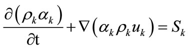 (1)
(1)
where, α, ρ and u are gas hold-up, density and velocity in each phase, respectively. k and Sk are phase type (for liquid phase: k = l and for gas phase: k = g) and source term of phase k in the domain, respectively.
2.2. Momentum Transfer Equation
The momentum transfer equation is derived as following:
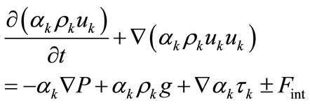 (2)
(2)
The right hand of the Equation (2) illustrates pressure difference (the first term), gravity force (the second term), stress (third term) and the ensemble averaged momentum exchange between the intra-phase force (fourth term) [36, 37].
The equations of state for the liquid and gas phases are derived as following:
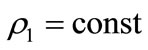 (3)
(3)
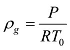 (4)
(4)
 (5)
(5)
where, αl and αg are liquid and gas volume fractions, respectively.
Fint takes into account the interaction forces (such as drag force, lift force and added mass force) between phases [38]. The drag and lift forces and turbulent stresses model employed in the current research are described in detail in the literature [39].
3. Simulation
The reference data were obtained from a published experimental work [1].Three internal loop airlift reactors with different volumes were simulated by fluent (version 6.3) as computational fluid dynamic (CFD). The specifications of three internal loop airlift reactors are shown in Table 1 [1].
In the simulation, the gas and liquid phases were air and water, respectively. The governing equations and constitutive relations have been discertized based on the finite element method [40]. At t = 0, all of the reactor volume is full of water and the volume fraction of air is equal to zero. The simulation will get steady state after 45 to 60 s. In the current simulation, the Reynolds Stress as Turbulence model and 2D Eulerian model as multiphase model were applied to study the hydrodynamic properties of gas and liquid phases in an internal airlift reactor under unsteady conditions. According to the simulation, the number of meshes was 7868. Boundary conditions for principal equations were assumed without any slip on the walls. For inlet and outlet, the boundary condition was the velocity inlet and the pressure outlet, respectively. The liquid phase was as primary phase and the gas phase was as dispersed phase. Figure 1(a) shows the distribution of gas
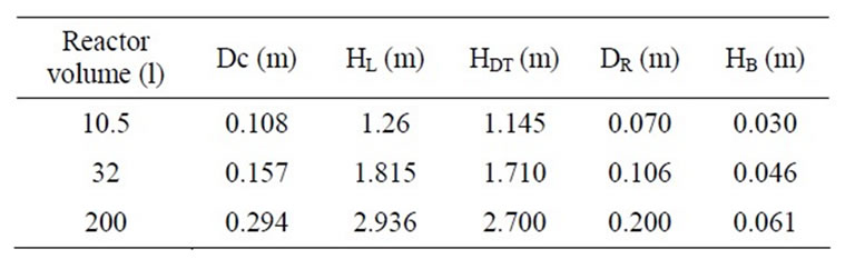
Table 1. Geometrical details of the reactors [1].
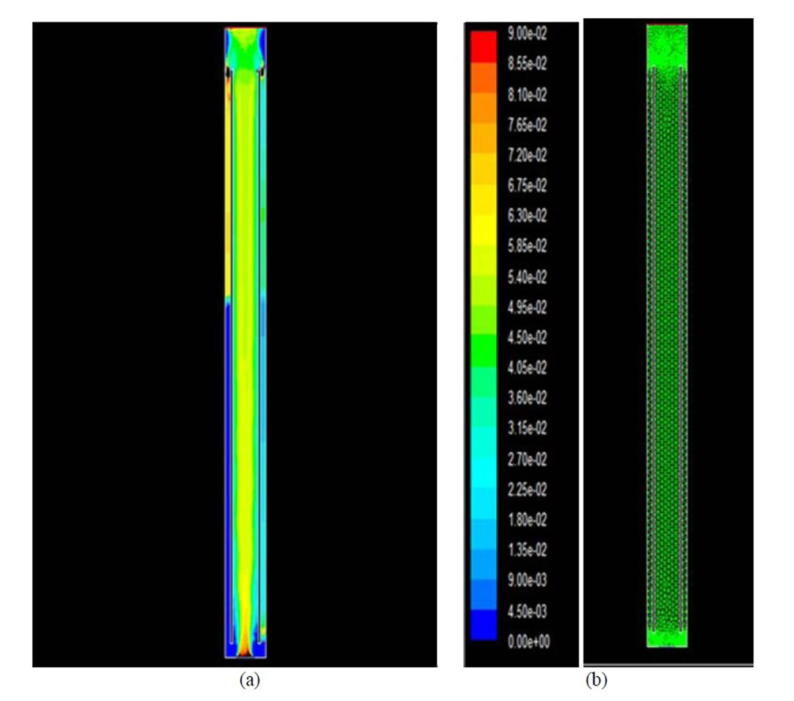
Figure 1. (a) Gas hold-up distribution in the reactor with volume of 10.5 l for water at superficial gas velocity of (Ug) 2 cm/s; (b) Meshes generation in the reactor with volume of 10.5 l.
hold-up in the reactor by volume of 10.5 for water at superficial gas velocity of (Ug) 2 cm/s. Figure 1(b) demonstrates the meshes generation.
4. Results and Discussion
Three airlift reactors (10.5, 32 and 200 l) with similar geometry were simulated at 20˚C and at atmospheric pressure. The hold-up in the riser and down-comer was studied, separately. Gas hold-up is an important parameter, because it determines the amount of the gas phase retained in the system at any time.
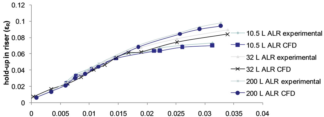
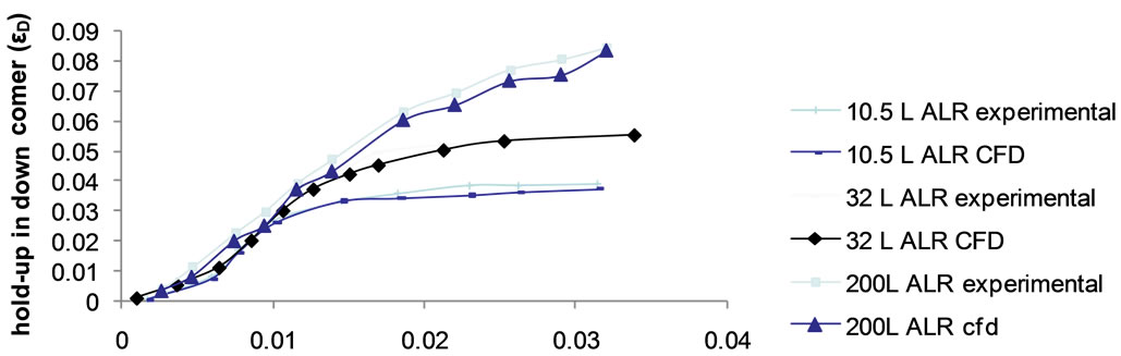
Figures 2 and 3 show the gas hold-up in the riser and down-comer versus superficial gas velocity for each reactor scale, experimentally [1] and theoretically (CFD). As shown in both figures, the gas hold-up increased by increasing the superficial gas velocity in the riser and down-comer for the three reactors and from superficial gas velocity equal to 0.015 m/s to up of this, the holdup in riser and down-comer increases with lower rate. Furthermore, the gas hold-up in the down-comer properly followed the gas hold-up in the riser in high superficial gas velocities. According to Figure 3, the gas hold-up in the down-comer was around zero in low superficial gas velocities. Moreover, a very good agreement between the experimental and theoretical data (CFD) can be observed.
Figure 4 shows gas hold-up in the riser versus gas hold-up in the down-comer based on the experiment and CFD for water. As shown in this figure, there is a linear trend between gas hold-up in the riser (εr) and gas hold-up in the down-comer (εd) for both experiment and CFD however some deviations were observed for few points. Its reason may be due to the experimental errors or our assumptions during the simulation. Furthermore, this figure clearly shows that gas hold-up increased in downcomer by increasing gas hold-up in the riser. An acceptable agreement was observed between the experimental data and CFD results.
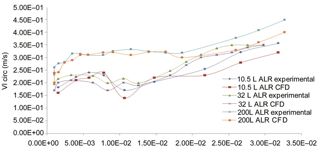
Figure 5 shows overall circulation velocity (VL) versus superficial gas velocity (Ug) for the experimental data and CFD results. As shown in this figure, overall circulation velocity approximately increased by increasing the superficial gas velocity although some deviations were observed for the reactor of 10.5 l (in the range of 0.0075 - 0.015 m/s for Ug) and for the reactor of 32 l (in the range of 0.005 - 0.015 m/s for Ug). In the most of points, the simulated results followed the experimental trends.
Figure 6 shows the volume fraction of gas with aeration of 0.03 m/s in the reactor of 10.5 l (as an example) in various times (up to steady state condition). As shown in this figure, bubbles rise in the airlift reactor and then bubbles accumulation and gas hold-up occur in it.
5. Conclusion
In this research, two-phase air-water flow in internal loop
 Ug (m/s)
Figure 2. Comparison between the experimental data and CFD results for gas hold-up in the riser versus superficial air velocity (Ug).
 Ug (m/s)
Figure 3. Comparison between the experimental data and CFD results for gas hold-up in the down-comer versus superficial air velocity (Ug).
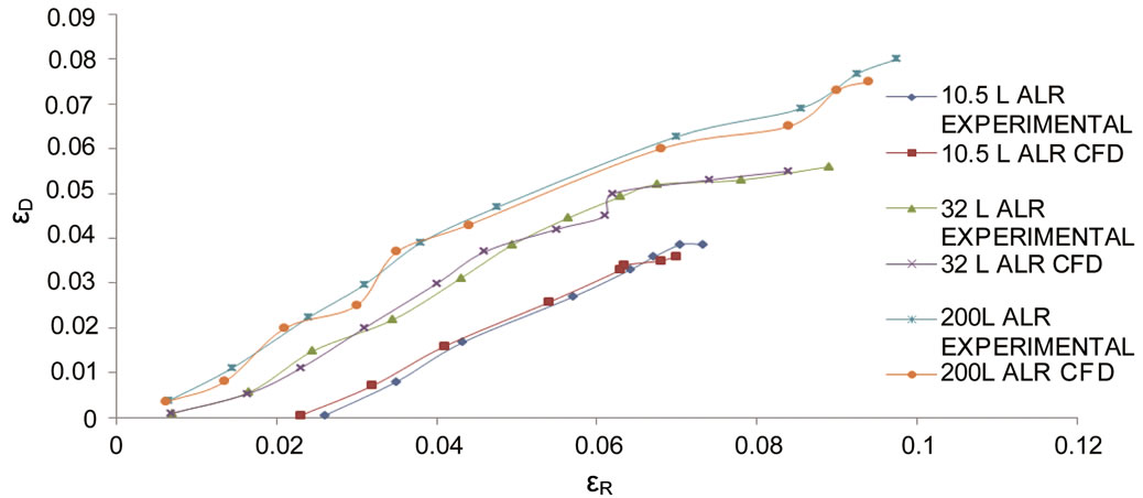
Figure 4. Gas hold-up in the riser versus gas hold-up in the down-comer based on the experiment and CFD.
 Ug (m/s)
Figure 5. Comparison between experimental data and CFD results for overall circulation velocity versus superficial gas velocity (m/s) in the riser.
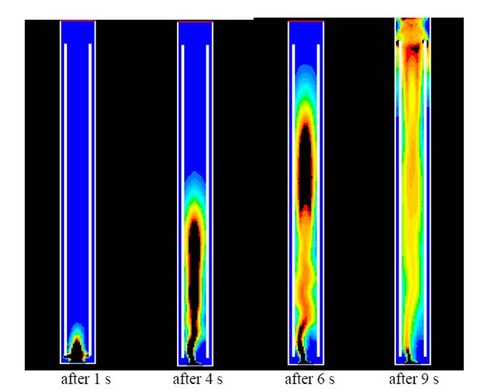
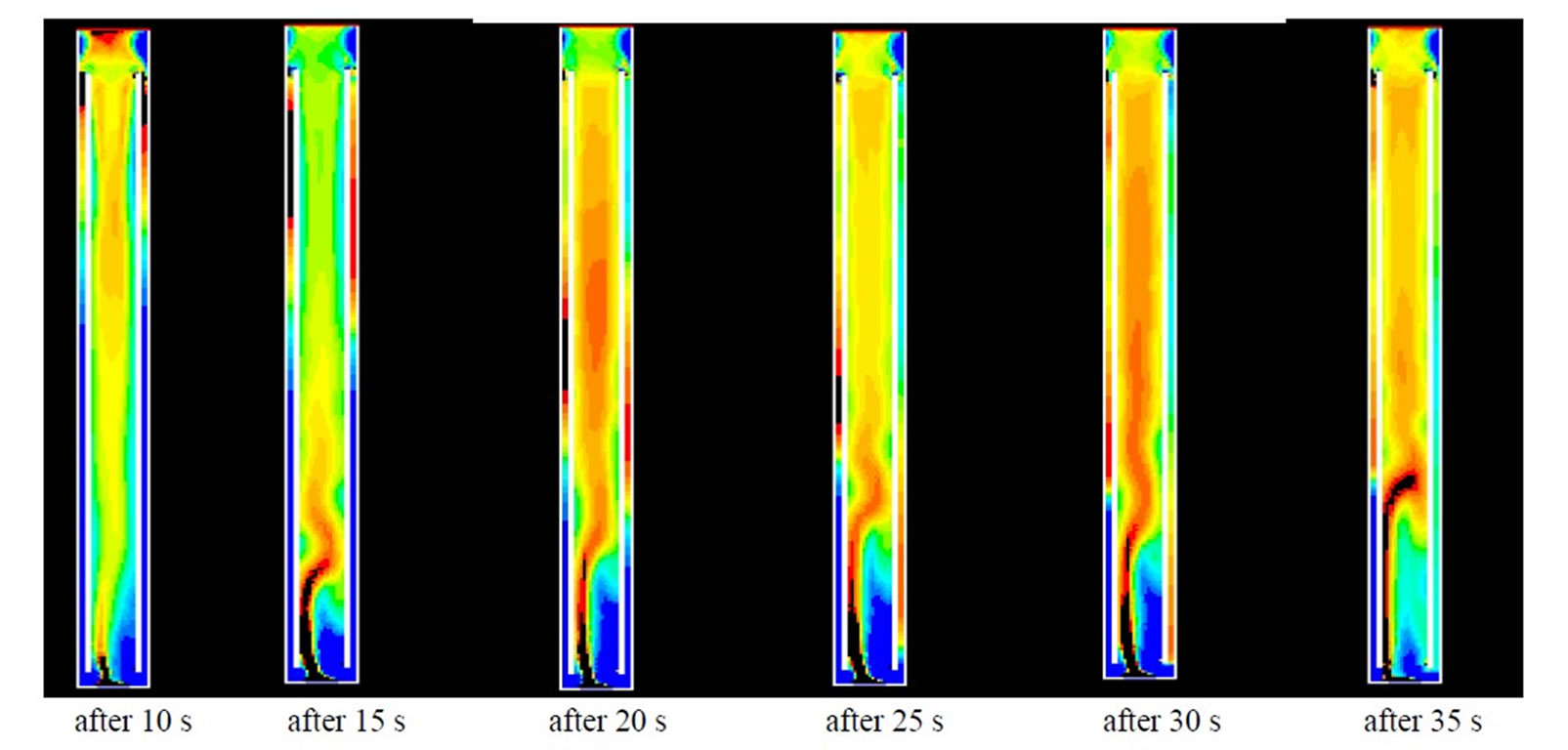
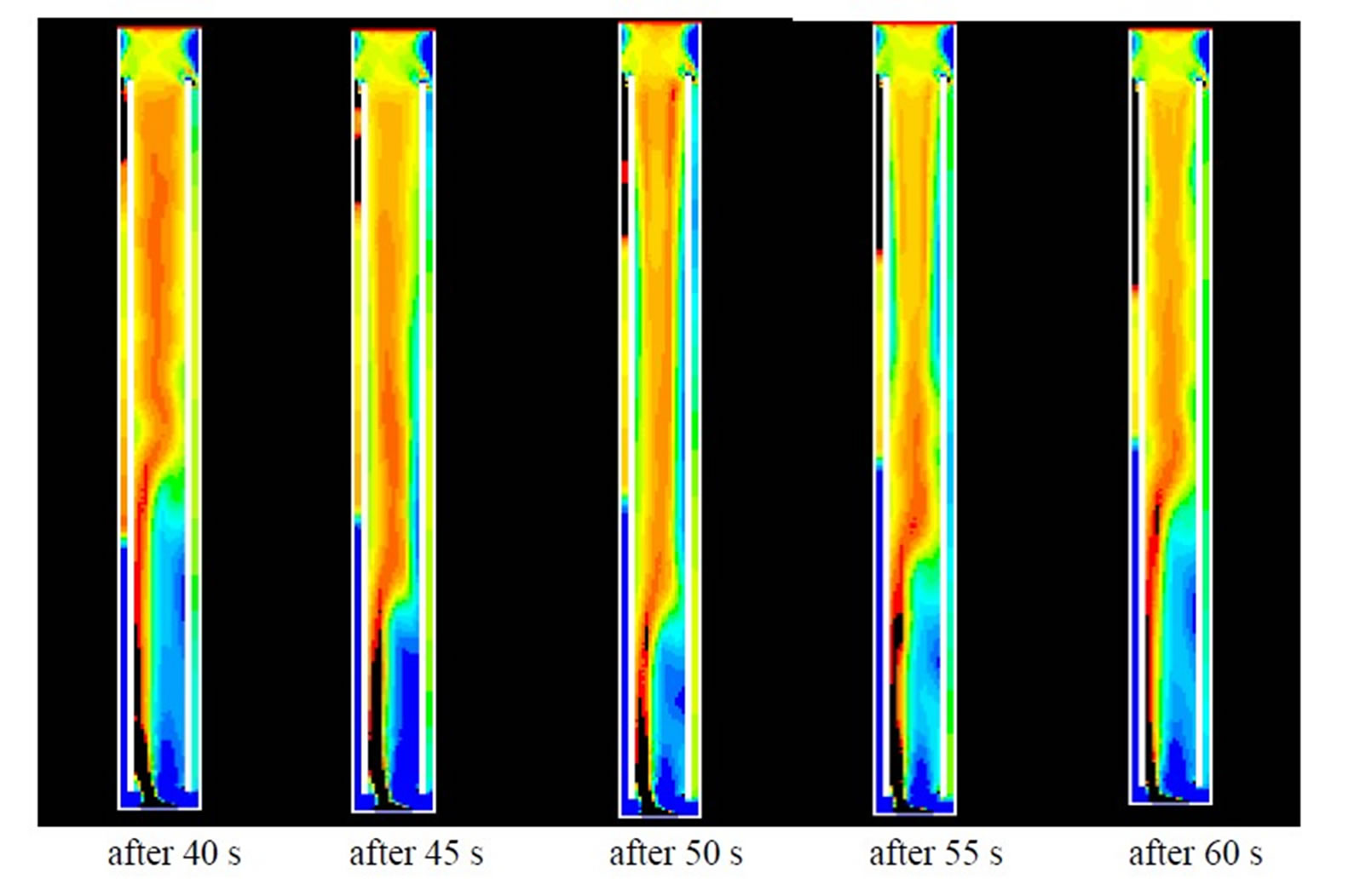
Figure 6. Volume fraction of air with aeration of 0.03 m/s in the reactor of 10.5 l.
airlift reactors [three various scales (10.5, 32 and 200 l)] was simulated using CFD. The results showed that the gas hold-up in the riser and down-comer for the three reactors increased by increasing the superficial gas velocity. Furthermore, an increase in superficial air velocity in the riser increased the overall circulation velocity for the three same reactors. These outputs were also supported by the published experimental work. Therefore, the simulated results were in very good agreement with the experimental data. It was concluded that the CFD is a very useful and accurate tool for scaling-up, as well.
REFERENCES
- M. Blažej, M. Kiša and J. Markoš, “Scale Influence on the Hydrodynamics of an Internal Loop Airlift Reactor,” Chemical Engineering and Processing, Vol. 43, No. 12, 2004, pp. 1519-1527. Hdoi:10.1016/j.cep.2004.02.003
- Z. Deng, T. Wang, N. Zhang and Z. Wang, “Gas Holdup, Bubble Behavior and Mass Transfer in a 5 m High Internal-Loop Airlift Reactor with Non-Newtonian Fluid,” Chemical Engineering Journal, Vol. 160, No. 1-2, 2010, pp. 729-737.
- M. Yoshimoto, S. Suenaga, K. Furumoto, K. Fukunaga and K. Nakao, “Gas-Liquid Interfacial Area, Bubble Size and Liquid-Phase Mass Transfer Coefficient in a ThreePhase External Loop Airlift Bubble Column,” Chemical and Biochemical Engineering Quarterly, Vol. 21, No. 4, 2007, pp. 365-372.
- J. A. Orejas, “Modeling and simulation of a BubbleColumn Reactor with External Loop: Application to the Direct Chlorination of Ethylene,” Chemical Engineering Science, Vol. 54, No. 21, 1999, pp. 5299-5309. Hdoi:10.1016/S0009-2509(99)00254-7
- M. A. Márquez, R. J. Amend, R. G. Carbonell, A. E. Sáez and G. W. Roberts, “Hydrodynamics of Gas-Lift Reactors with a Fast, Liquid-Phase Reaction,” Chemical Engineering Science, Vol. 54, No. 13-14, 1999, pp. 2263-2271. Hdoi:10.1016/S0009-2509(98)00351-0
- R. J. G. M. Van der Lans, “Hydrodynamics of a Bubble Column Loop Reactor,” Ph.D. Thesis, Delft University of Technology, Delft, 1985.
- E. Camarasa, E. Carvalho, L. A. C. Meleiro, R. MacielFilho, A. Domingues, G. Wild, S. Poncin, N. Midoux and J. Bouillard, “Development of a Complete Model for an Air-Lift Reactor,” Chemical Engineering Science, Vol. 56, No. 2, 2001, pp. 493-502. Hdoi:10.1016/S0009-2509(00)00253-0
- Y. Chisti, “Airlift Bioreactors,” Elsevier, London, 1989.
- M. Trager, G. N. Qazi, U. Onfen and C. L. Chopra, “Comparison of Airlift and Stirred Reactors for Fermentation with Aspergillusniger,” Journal Fermentation Bioengineering, Vol. 68, No. 10, 1989, pp. 112-116. Hdoi:10.1016/0922-338X(89)90058-5
- Y. S. Park, N. Ohta and M. Okabe, “Effect of Dissolved Oxygen Concentration and Impeller Tip Speed on Itaconic Acid Production by Aspergillusterreus,” Biotechnology Letters, Vol. 15, No. 6, 1993, pp. 583-586. Hdoi:10.1007/BF00138544
- B. Sajjadi, M. K. Moraveji and R. Davarnejad, “Investigation of Bubble Diameter and Flow Regime between Water and Dilute Aqueous Ethanol Solutions in an Airlift Reactor,” Frontiers of Chemical Science and Engineering, Vol. 5, No. 2, 2011, pp. 194-202. Hdoi:10.1007/s11705-010-1019-2
- J. B. Joshi, V. V. Ranade, S. D. Gharat and S. S. Lele, “Sparged Loop Reactors,” Canadian Journal Chemical Engineering, Vol. 68, No. 5, 1990, pp. 705-716. Hdoi:10.1002/cjce.5450680501
- J. C. Merchuk, G. Osemberg, M. Siegel and M. Shacham, “A Method for Evaluation of Mass Transfer Coefficients in the Different Regions of Airlift Reactors,” Chemical Engineering Science, Vol. 47, No. 9-11, 1992, pp. 3517- 3525. Hdoi:10.1016/0009-2509(92)87038-R
- A. B. Russel, C. R. Thomas and M. D. Lilly, “The Influence of Height and Top-Section Size on the Hydrodynamic Characteristics of Airlift Fermentors,” Biotechnology and Bioengineering, Vol. 43, No. 1, 1994, pp. 69-76. Hdoi:10.1002/bit.260430110
- M. Siegel and J. C. Merchuk, “Hydrodynamics in Rectangular Airlift Reactors, Scale-Up and the Influence of Gas-Liquid Separator Design,” Canadian Journal Chemical Engineering, Vol. 69, No. 2, 1991, pp. 465-473. Hdoi:10.1002/cjce.5450690210
- J. C. Merchuk and R. Younger, “The Role of Gas-Liquid Separator of Airlift Reactors in the Mixing Process,” Chemical Engineering Science, Vol. 45, No. 9, 1990, pp. 2973-2975. Hdoi:10.1016/0009-2509(90)80191-G
- M. M. Siegel and J. C. Merchuk, “Mass Transfer in Airlift Reactors: Effects of Gas Recirculation,” In: J. W. Moody and P. B. Baker, Eds., Bioreactors and Biotransformation, Elsevier, London, 1987, p. 350.
- M. Siegel, J. C. Merchuk and K. Schugerl, “Air-Lift Reactor Analysis: Interrelationships between Riser, DownComer, and Gas-Liquid Separator Behavior, including Gas Recirculation Effects,” AIChE Journal, Vol. 32, No. 10, 1986, pp. 1585-1596. Hdoi:10.1002/aic.690321002
- Y. Bando, H. Hayakawa and M. Nakamura, “Effect of Equipment Dimensions on Liquid Mixing Time of Bubble Column with Draft Tube,” Journal Chemical Engineering Japan, Vol. 31, No. 5, 1998, pp. 765-770. Hdoi:10.1252/jcej.31.765
- J. C. Merchuk, N. Ladwa, A. Cameron, M. Bulmer and A. Picket, “Concentric-Tube Airlift Reactors: Effects of Geometrical Design on Performance,” AIChE Journal, Vol. 40, No. 7, 1994, pp. 1105-1117. Hdoi:10.1002/aic.690400703
- H. Blenke, “Loop Reactors,” Advances in Biochemical Engineering/Biotechnology, Vol. 13, 1979, pp. 121-214. Hdoi:10.1007/3540094687_8
- T. J. Lin and P. C. Chen, “Studies on Hydrodynamics of an Internal-Loop Airlift Reactor in Gas Entrainment Regime by Particle Image Analyzer,” Chemical Engineering Journal, Vol. 108, No. 1-2, 2005, pp. 69-79. Hdoi:10.1016/j.cej.2005.01.001
- Y. Kawase and M. Moo-Young, “Hydrodynamics in Bubble Column Bioreactors with Fermentation Broths Having a Yield Stress,” Applied Microbial and Biotechnology, Vol. 30, No. 6, 1989, pp. 596-603. Hdoi:10.1007/BF00255365
- J. J. Heijnen, J. Hols, R. J. G. M. van der Lans, H. L. J. M. van Leeuwen, A. Mulder and R. Weltevrede, “A Simple Hydrodynamic Model for the Liquid Circulation Velocity in a Full-Scale Twoand Three-Phase Internal Airlift Reactor Operating in the Gas Recirculation Regime,” Chemical Engineering Science, Vol. 52, No. 15, 1997, pp. 2527-2540. Hdoi:10.1016/S0009-2509(97)00070-5
- M. Siegel and J. C. Merchuk, “Hydrodynamics in Rectangular Airlift Reactors, Scale-Up and the Influence of Gas-Liquid Separator Design,” Canadian Journal of Chemical Engineering, Vol. 69, No. 2, 1991, pp. 465-473. Hdoi:10.1002/cjce.5450690210
- T.-J. Lin and P.-C. Chen, “Studies on Hydrodynamics of an Internal-Loop Airlift Reactor in Gas Entrainment Regime by Particle Image Analyzer,” Chemical Engineering Journal, Vol. 108, No. 1-2, 2005, pp. 69-79. Hdoi:10.1016/j.cej.2005.01.001
- M. Tobajas, M. Siegel and S. A. Apitz, “Influence of Geometry and Solid Concentration on the Hydrodynamics and Mass Transfer of a Rectangular Airlift Reactor for Marine Sediment and Soil Bioremediation,” Chemical Engineering Journal, Vol. 77, 1999, pp. 660-669.
- C. Freitas and J. A. Teixeira, “Hydrodynamic Studies in an Air-Lift Reactor with Enlarged Degassing Zone,” Bioprocess and Biosystems Engineering, Vol. 18, No. 4, 1998, pp. 267-279. Hdoi:10.1007/s004490050441
- A. A. Vicent and J. A. Teixeira, “Hydrodynamic Performance of Three-Phase Airlift Bioreactors with Enlarged Degassing Zone,” Bioprocess and Biosystems Engineering, Vol. 14, No. 1, 1995, pp. 17-22. Hdoi:10.1007/BF00369848
- P. M. Kilonzo, A. Margaritis, M. A. Bergougnou, J. T. Yu and Y. Qin, “Influenceof the Baffle Clearance Design on Hydrodynamics of a Two Riser Rectangular Airlift Reactor with Inverse Loop and Expanded Gas-Liquid Separator,” Chemical Engineering Journal, Vol. 121, No. 1, 2006, pp. 17-26. Hdoi:10.1016/j.cej.2006.05.003
- E. Molina, A. Contreras and Y. Chisti, “Gas Holdup, Liquid Velocity and Mixing Behavior of Viscous Newtonian Media in a Split-Cylinder Airlift Bioreactor,” Trans IChemE, Vol. 77, 1999, pp. 27-32.
- S. Wachi, A. G. Jones and T. P. Elson, “Flow Dynamic in Draft Tube Bubble Column Using Various Liquid,” Chemical Engineering Science, Vol. 46, No. 2, 1991, pp. 657-663. Hdoi:10.1016/0009-2509(91)80026-U
- J. Philip, J. M. Proctor, K. Niranjan and J. F. Davidson, “Gas Holdup and Liquid Circulation in Internal Loop Reactors Containing Highly Viscous Newtonian and Non-Newtonian Liquids,” Chemical Engineering Science, Vol. 45, No. 3, 1990, pp. 651-664. Hdoi:10.1016/0009-2509(90)87008-G
- K. Koide, H. Sato and S. Iwamoto, “Gas Holdup and Volumetric Liquid-Phase Mass Transfer Coefficient in Bubble Column with Draught Tube and with Gas Dispersion into Annulus,” Journal of Chemical Engineering of Japan, Vol. 16, No. 5, 1983, pp. 413-419. Hdoi:10.1252/jcej.16.413
- M. E. Abashar, U. Narsingh, A. E. Rouillard and R. Judd, “Hydrodynamic Flow Regimes, Gas Hold-Up, and Liquid Circulation in Airlift Reactors,” Industrial & Engineering Chemistry Research, Vol. 37, No. 4, 1998, pp. 1251-1259. Hdoi:10.1021/ie9704612
- I. M. Šijački, R. R. Čolović, D. Lj. Petrović, M. N. Tekić and M. S. Đurić, “Diluted Alcohol Solutions in Bubble Columns and Draft Tube Airlift Reactors with a Single Orifice Sparger: Experiments and Simple Correlations,” Journal Chemical Technology and Biotechnology, Vol. 85, No. 1, 2010, pp. 39-49. Hdoi:10.1002/jctb.2266
- B. Albijanić, V. Havran, D. Lj. Petrović, M. Đurić and M. N. Tekić, “Hydrodynamics and Mass Transfer in a Draft Tube Airlift Reactor with Dilute Alcohol Solutions,” AIChE Journal, Vol. 53, No. 11, 2007, pp. 2897-2904. Hdoi:10.1002/aic.11306
- M. K. Moraveji, B. Sajjadi and R. Davarnejad, “CFD Simulation of Hold-Up and Liquid Circulation Velocity in a Membrane Airlift Reactor,” Theoretical Foundations of Chemical Engineering, Vol. 46, No. 3, 2012, pp. 266- 273. Hdoi:10.1134/S0040579512020078
- M. K. Moraveji, B. Sajjadi, M. Jafarkhani and R. Davarnejad, “Experimental Investigation and CFD Simulation of Turbulence Effect on Hydrodynamic and Mass Transfer in a Packed Bed Airlift Internal Loop Reactor,” International Communications in Heat and Mass Transfer, Vol. 38, No. 4, 2011, pp. 518-524. Hdoi:10.1016/j.icheatmasstransfer.2010.12.033
- M. K. Moraveji, E. Ghaderi and R. Davarnejad, “Effective Parameters Consideration in Ohmic Heating Process in Two Phase Static System of Bio-Particle-Liquid,” International Journal of Food Engineering, Vol. 7, No. 1, 2011, pp. 1-17.
NOTES
*Corresponding author.