Engineering
Vol.4 No.11(2012), Article ID:24580,4 pages DOI:10.4236/eng.2012.411100
Evaluation of the Ultimate Capacity of Friction Piles
Faculty of Engineering, Sinai University, El Arish, Egypt
Email: wael_nashaat74@yahoo.com
Received July 14, 2012; revised August 20, 2012; accepted September 4, 2012
Keywords: Soil; Pile Capacity; Bored Pile; Friction Pile; Pile Load
ABSTRACT
The precise prediction of maximum load carrying capacity of bored piles is a complex problem because the load is a function of a large number of factors. These factors include method of boring, method of concreting, quality of concrete, expertise of the construction staff, the ground conditions and the pile geometry. To ascertain the field performance and estimate load carrying capacities of piles, in-situ pile load tests are conducted. Due to practical and time constraints, it is not possible to load the pile up-to failure. In this study, field pile load test data is analyzed to estimate the ultimate load for friction piles. The analysis is based on three pile load test results. The tests are conducted at the site of The Cultural and Recreational Complex project in Port Said, Egypt. Three pile load tests are performed on bored piles of 900 mm diameter and 50 m length. Geotechnical investigations at the site are carried out to a maximum depth of 60 m. Ultimate capacities of piles are determined according to different methods including Egyptian Code of practice (2005), Tangent-tangent, Hansen (1963), Chin (1970), Ahmed and Pise (1997) and Decourt (1999). It was concluded that approximately 8% of the ultimate load is resisted by bearing at the base of the pile, and that up to 92% of the load is resisted by friction along the shaft. Based on a comparison of pile capacity predictions using different method, recommendations are made. A new method is proposed to calculate the ultimate capacity of the pile from pile load test data. The ultimate capacity of the bored piles predicted using the proposed method appears to be reliable and compares well to different available methods.
1. Introduction
Pile foundation is an important link in transferring the structural load to the bearing ground located at some depth below ground surface. The design of piles accounts for various parameters such as the nature of substrata, depth of ground water table, depth of the bearing stratum, and type and level of load to be supported. To ascertain the field performance and estimate the load carrying capacity, in-situ pile load tests are relied upon.
A simple method for calculating static shaft resistance of a pile driven into clay is presented by Mirza (1997) [1]. The method is based on correlations derived for marine clays between index properties and strengths. Applications of the method to half a dozen full scale pile load tests of high quality are described. Except for short piles in very stiff to hard clays, the predictions agree well with the field test measurements. The correlation presented allows an assessment of residual skin friction and indicates the importance of the liquidity index of the clay in static capacity calculations.
Dewaikar and Pallavi (2000) presented analysis of field pile load tests data to estimate the ultimate pile load. The analysis is based on forty pile load tests results collected from various infrastructure and building sites in Mumbai region of India. Collected data is analyzed using various graphical and semi-empirical methods available in literature [2].
Nabil (2001) studied the behavior of bored pile groups in cemented sands by a field testing program at a site in South Surra, Kuwait. The program consisted of axial load tests on single bored piles in tension and compression. Two groups of piles, each consisting of five piles were tested. The spacing between the piles in the groups was twoand three-pile diameters. The calculated pile group efficiencies were 1.22 and 1.93 for a pile spacing of twoand three-pile diameters, respectively. Since settlement usually controls the design of pile groups in sand, the group factor, defined as the ratio of the settlement of the group to the settlement of a single pile at comparable loads in the elastic range, was determined from test results [3].
Abdelrahman et al. (2003) suggested that axial pile loading tests on single pile may offer the justification of the pile design load. Codes for deep foundations design stipulate the acceptance criteria for piles tested in compression based on specified limits for pile settlement at specified load levels. The researchers examined the different methods used in interpreting pile load test results. Sixty-four continuous flight auger piles were tested using the maintained load test method and the results were analyzed using the different methods of interpretation [4].
Wehnert and Vermeer (2004) analyzed the load results of short large diameter bored pile tested in Germany. The results for total resistance as well as for base and shaft resistance are presented. The pile is assumed to be linear elastic. Different constitutive models for the subsoil such as elastic-plastic, Mohr-Coulmb, are used [5].
A new approach for the design of large diameter bored piles resting on cohesionless soils was suggested by Radwan et al. (2007) [6]. The approach is based on the results obtained from finite element analysis performed using data from thirty case histories of large diameter bored piles collected from several construction projects. Both unit end bearing and skin friction resistance are estimated taking the settlement criterion into account. Mohr-Coulomb constitutive model is used in the numerical model. Eventually, statistical study is conducted to evaluate the improvement, accuracy, and reliability of design using the new approach, compared with the prediction of the Egyptian Code (2005) [7].
Akbar et al. (2008) presented the experience gained from four pile load tests at a site in the North West Frontier Province of Pakistan. Geotechnical investigations at the site are carried out to a maximum depth of 60 m. The soil at the site is predominantly hard clays within the investigated depth with thin layers of gravels and boulders below 40 m depth. Four piles of diameters varying from 660 mm to 760 mm and length ranging between 20 m and 47.5 m were subjected to axial loads. Using the pile load test results, back calculations are carried out to estimate the appropriate values of pile design parameters [8].
A probabilistic model as a complementary mathematical base for the traditional deterministic approach to quantify the selection of a factor of safety for each term of the load equation of friction piles in clay is presented by Al Jairry (2009) [9].
From the above, the variation in the load estimates of available methods is too much. Thus, additional study on friction pile capacity is needed to be done. However, the objective of this study is to provide the results of pile tests and develop a formula for closer prediction of the pile capacity.
2. Soil Investigation
There have not been many tests on the soil in Port Said in Egypt. The investigated site is the Cultural and Recreation Complex project located in the city of Port Said. The project is built on an area of approximately 50 × 70 m. A comprehensive geotechnical investigation was conducted. The investigation included seven borings. The general layout of site is shown in Figure 1.
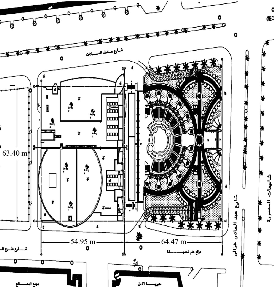
Figure 1. General layout of the site.
Soil Stratification
The soil profile in the investigated site is shown in Figure 2. The profile indicates that the following soil stratifications are encountered:
1) From elevation 0.00 to –10.00 m calcareous sitysand with broken shells.
2) From elevation –10.00 to –17.00 m soft silty-clay with interval of sand.
3) From elevation –17.00 to –49.00 m soft silty-clay with traces of sand.
4) From elevation –49.00 to –52.00 m calcareous sitysand.
5) From elevation –52.00 to –60.00 m hard silty-clay with intervening calcareous silty-sand.
The ground water table has been found to be at 0.70 meter from the ground surface.
3. Prediction of Pile Load Capacity Using Egyptian Code
Various field and laboratory tests are carried out during the geotechnical investigation for the evaluation of subsurface conditions and the pile design parameters at the project site. The code pile capacities are calculated using the provisions of the Egyptian code (2005) [7]. The pile diameter is taken as 900 mm and pile length is 50 m. Tables 1-3 summarize the soil properties as well as outlining the calculated pile resistance (shaft friction and end bearing). Figure 3 shows the calculated ultimate capacity of the pile. Based on data from the figure, the ultimate pile capacity, Qult is obtained as 4622.81 kN/m2. By applying a factor of safety, F.S. of 2, the allowable design pile capacity, Qall is 2311.41 kN/m2. The allowable bearing capacity of the pile adopted for the design is taken as 2300 kN/m2.
4. Pile Load Tests
Three pile load tests are performed on bored piles of 900 mm diameters and 50 m lengths. One of the piles is non-working pile test #1 and two are working piles tests #2 and #3. The nonworking pile test #1 is loaded to twice the working load of 230 ton while the working piles for tests #2 and #3 are loaded to 1.5 times the working load.
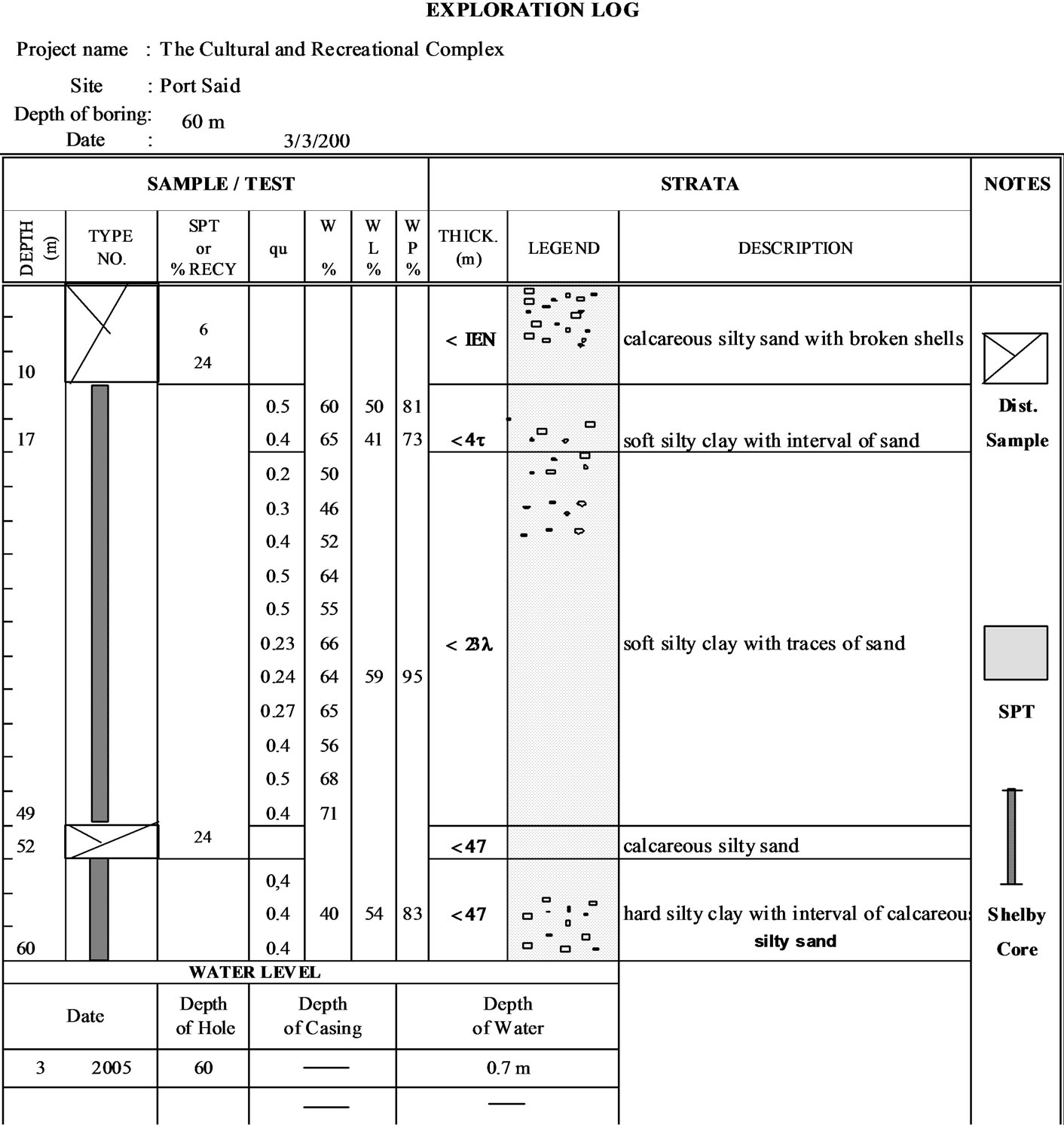
Figure 2. Soil profile of the investigated site.
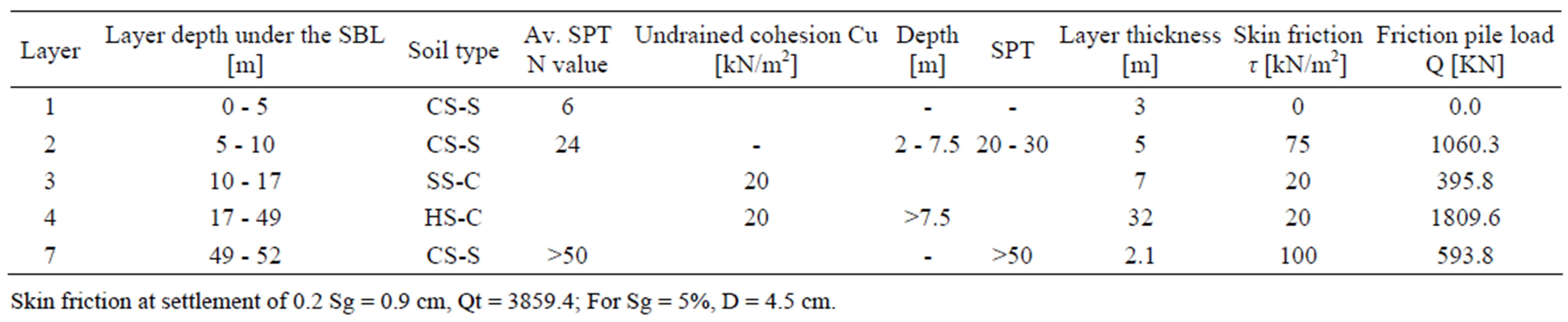
Table 1. Calculated skin friction to be used in the design of pile according to the Egyptian Code [7].
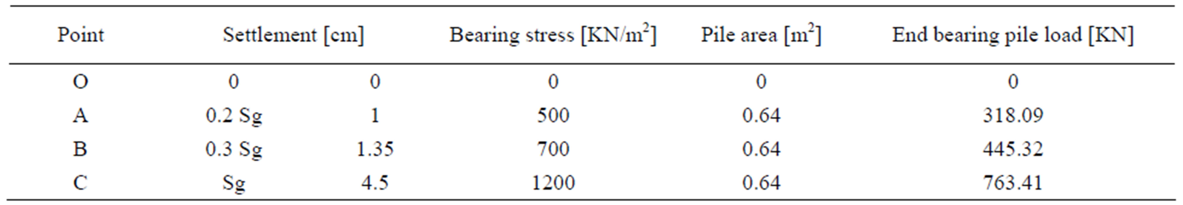
Table 2. Calculated end bearing resistance to be used in the design according to the Egyptian Code [7].
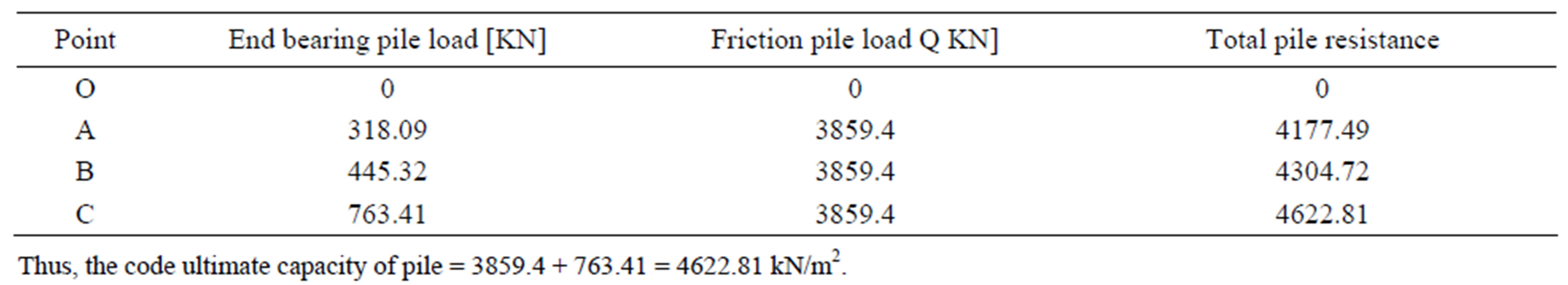
Table 3. Total pile load to be used in the design according to the Egyptian Code [7].
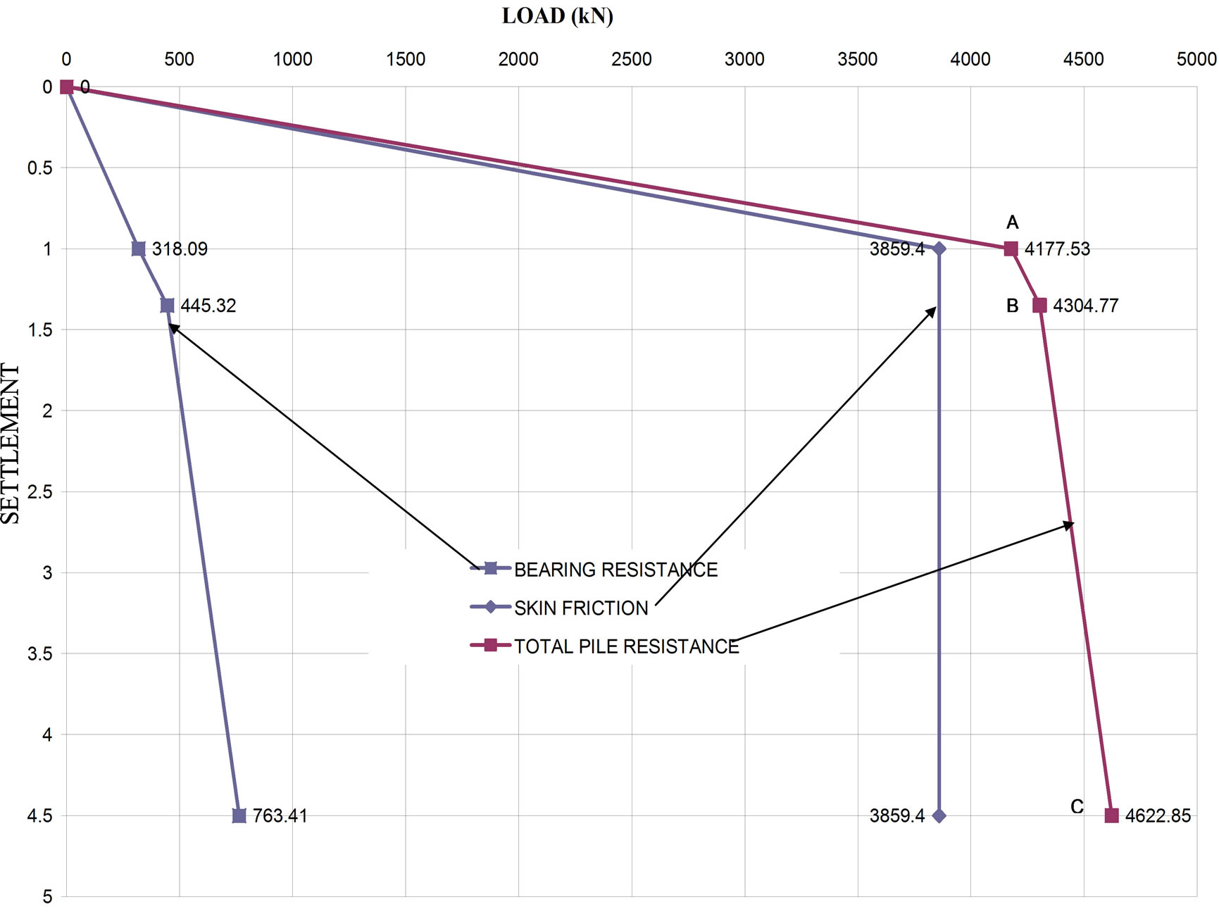
Figure 3. Shows the relationship between calculated capacity and settlement for the bored pile according the Egyptian Code.
4.1. Reaction System
The reaction system for the test piles was provided by a test head restrained by twelve ground anchors distributed around the pile as shown in the test setup in Figure 4.
4.2. Loading of Pile
The load was applied using three hydraulic jacks placed between the pile head and the anchored test head as shown in Figures 4 and 5. The loading cycles increment adopted for the test piles according Egyptian code.
4.3. Test Measurements
1) Measurement of load The load was measured by calibrated load cells with digital readout device. Load cells were seated on top of spherical bearing plates placed above the hydraulic jacks. Also, the applied load was checked by recording the applied hydraulic pressure by a pressure gauge mounted on the pumping unit.
2) Measurement of pile head settlement Settlement of the pile head is measured using three dial gauges of precision of 0.01 mm.
4.4. Test Results
1) General Observation during tests a) Settlement of pile did not reach 10% of its nominal diameter.
b) The test piles did not show any sign of geotechnical failure. This means that the test piles did not continue to settle or sink without increase in the applied load.
c) No section of the test piles failed structurally.
The load-settlement relationships for pile load tests are shown in Figure 6.
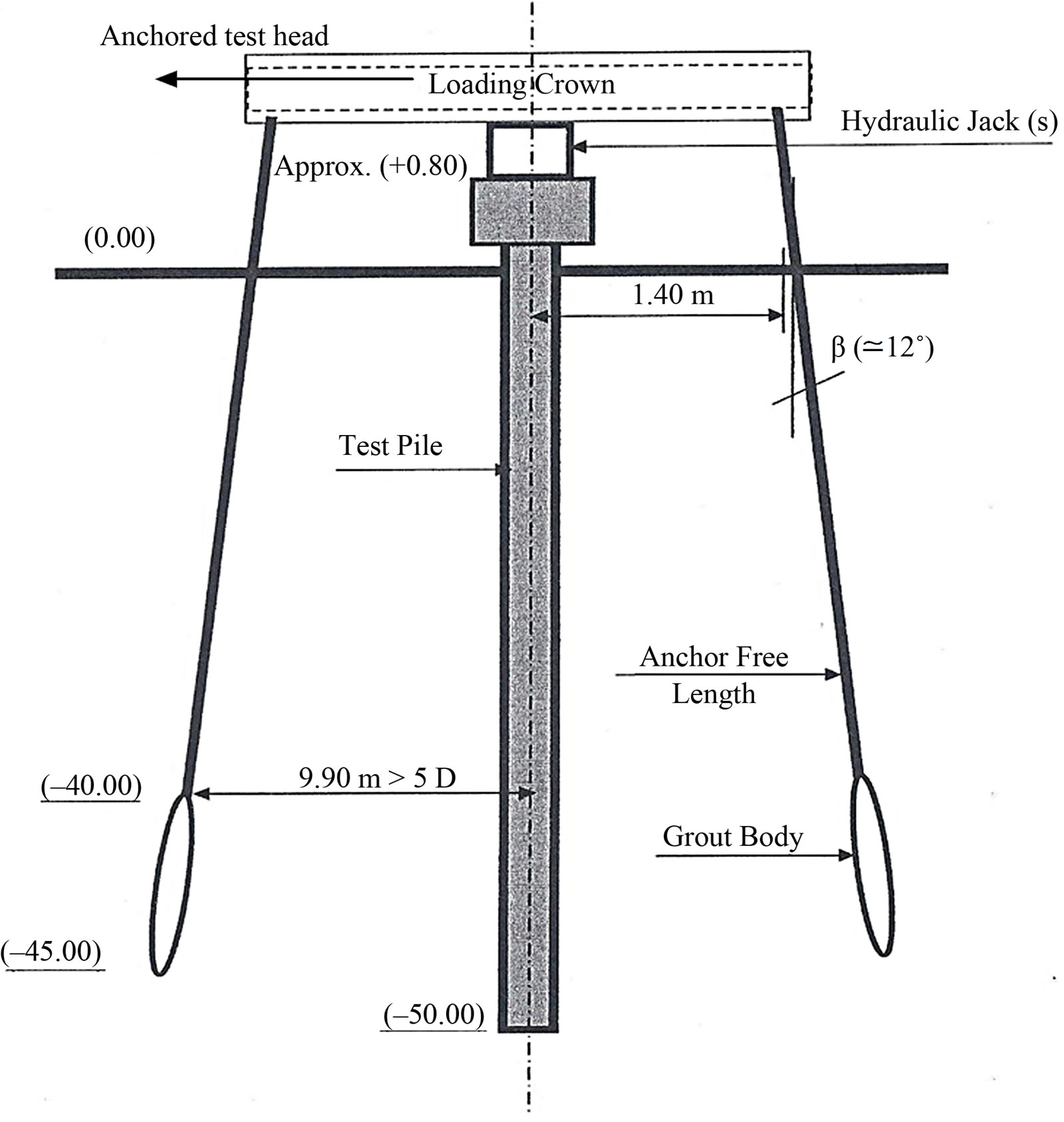
Figure 4. Test setup.
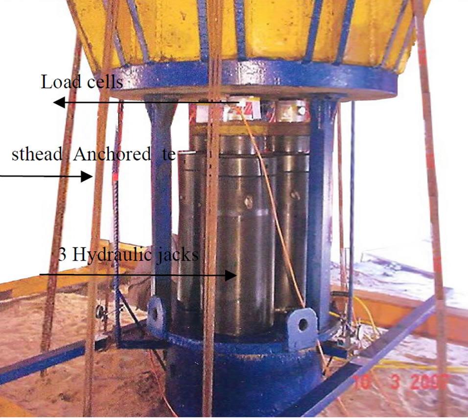
Figure 5. Pile loading setup.
d) Head Settlement is recorded in Table 4. It is noted that no sign of plunging is detected.
5. Ultimate Capacity of Piles
The ultimate capacities of the piles are determined from the load test results using different approaches.
5.1. Tangent—Tangent Method
Applying tangent—tangent method, a plot is made between load divided by cross sectional area of pile and the settlement on semi logarithmic scale as shown in Figure 7 for working pile load test #2 [7].
5.2. Hansen Method (1963)
Applying Hansen Method the square root of each settlement value from field load test data divided by the corresponding load value is plotted against the settlement as shown in Figure 8 for working pile load test #3. Estimation of the ultimate load by Hansen Method is given by the formula [10]:
 (1)
(1)
where:
Qu = ultimate load capacity.
C1 = slope of the best fitting straight line.
C2 = y-intercept of the straight line.
5.3. Chin’s Method (1970)
Applying Chin’s method, a plot is made between settlement divided by corresponding load and the settlement as shown in Figure 9 for non-working test pile #1. The inverse slope of the straight line gives the ultimate load as proposed by Chin [11].
Figure 6. Load-settlement relationship for non-working pile load test #1.
Table 4. Recorded head settlement.
Figure 7. Ultimate pile capacities by tangent—tangent method for working pile load test #2.
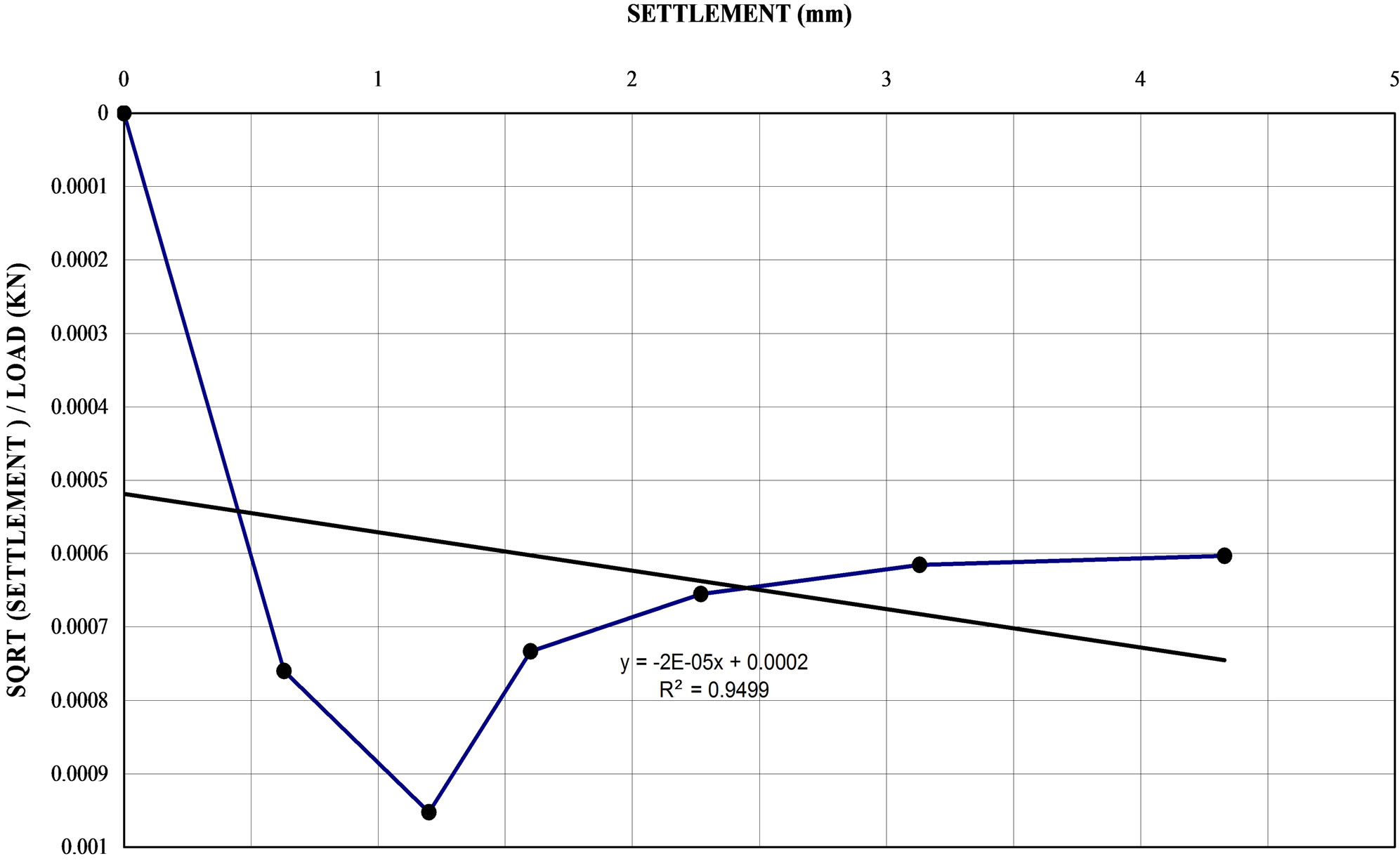
Figure 8. Ultimate pile capacities by Hansen method for working pile load test #3.
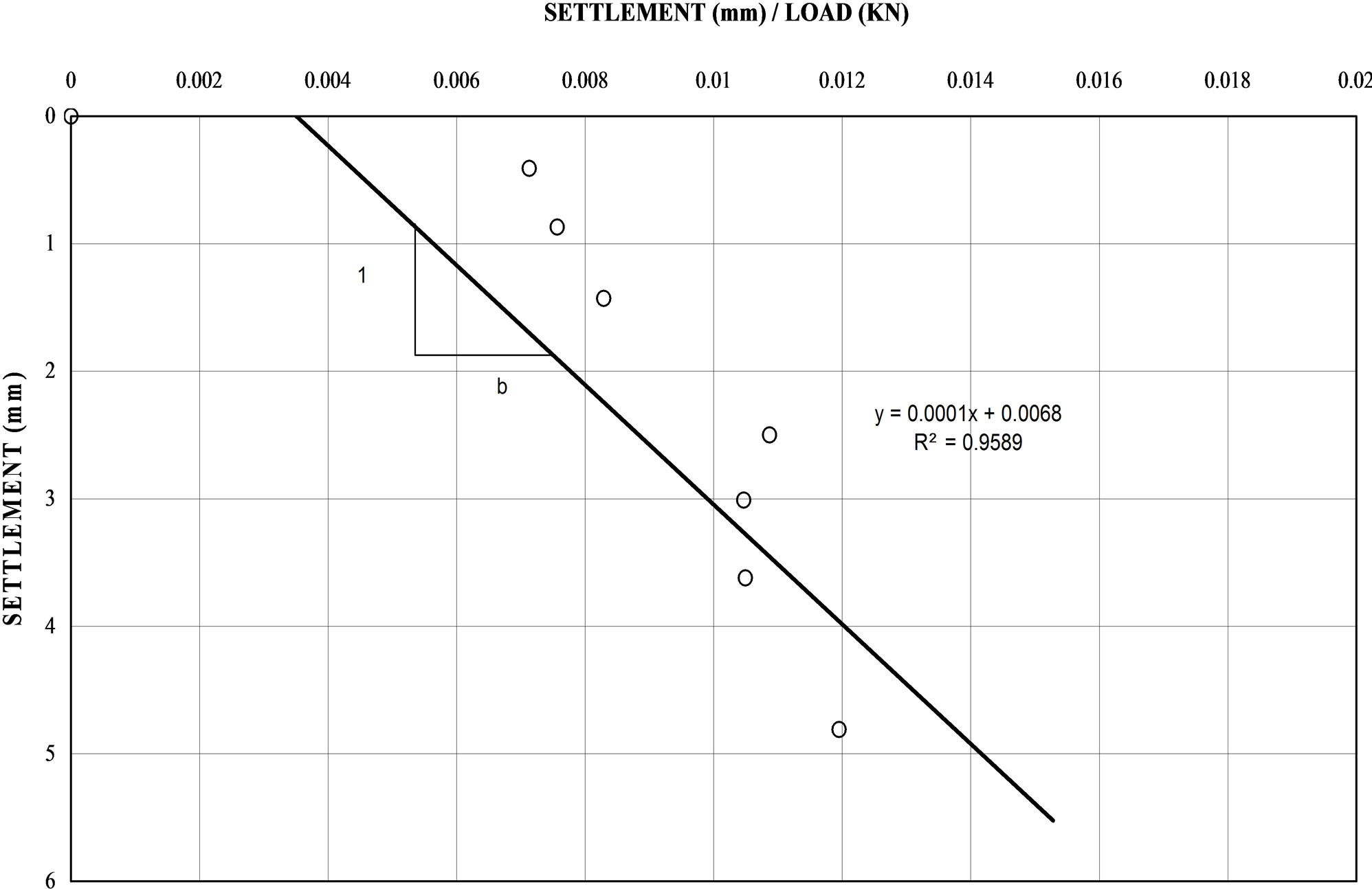
Figure 9. Ultimate pile capacity by Chin method for non-working test pile #1.
5.4. Ahmad and Pise (1997)
Ahmad and Pise (1997) proposed a reduction factor to Chin’s extrapolated value of the ultimate capacity. In the settlement/load vs. settlement plot, it was observed that, generally two straight lines could be drawn through these points. As shown in Figure 10 for non-working test pile #1, the ratio of settlement ΔS (settlement between the point of intersection of two straight lines and that corresponding to final test load) to S (total settlement) is taken to be the reduction factor (RF) for that set of test data [12]. However, reduction factor (RF) is given by the following:
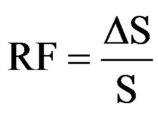 (2)
(2)
where:
RF = Reduction factor.
Qmod = Modified Chin’s value of ultimate capacity.
Qch = Chin’s value of ultimate capacity.
5.5. Decourt’s Extrapolation (1999)
Applying Decourt’s Extrapolation by dividing each load by its corresponding settlement and ploting the resulting values against the applied load. A linear regression over the apparent line (last three points) determines a line. Decourt identified the ultimate load as the intersection of this line with load axis as shown in Figures 11 for working test pile #3 [13].
6. Proposed Method for Determination of Ultimate Pile Capacity from Load Test
The load vs settlement behavior of the pile is extrapolated using an empirical method. The estimation of ultimate load consists of two steps as given below:
1) Plotting load settlement curve from field load test data as shown in Figures 12-14.
2) The ultimate pile capacity is given by the empirical formula:
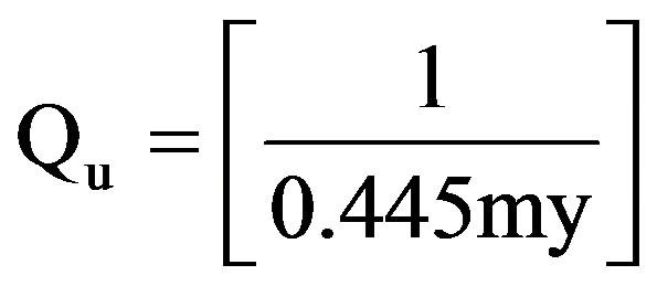 (3)
(3)
where:
Qu = ultimate load capacity (kN).
m = slope of the trend straight line.
y = y-intercept of the straight line (as a value without sign).
7. Comparison between Different Methods for Determination of Ultimate Pile Capacity
The calculation of the ultimate capacity of piles and the corresponding factors of safety using the above mention methods are summarized in Table 5.
The ultimate loads obtained by various methods from the pile load test results are shown in Figure 15.
8. Load Carried by End Bearing and Friction along Shaft
From Table 6 the values of the ultimate pile capacity were taken to evaluate the percentage of friction and end bearing capacity from Figure 3. Based on the above findings, it was found that the percentage of load carried by friction along the pile shaft and the end bearing are shown in the following Table 6.
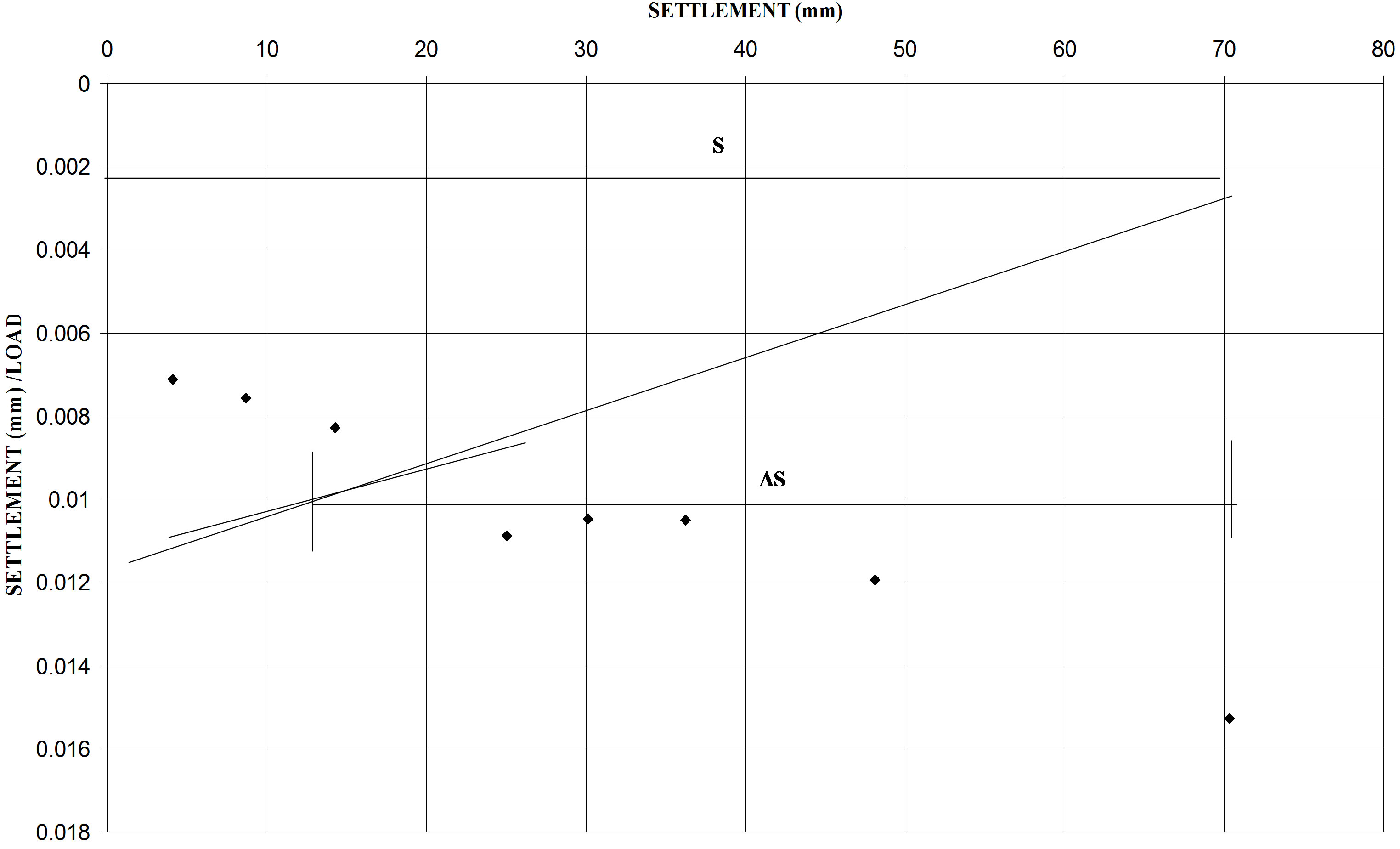
Figure 10. Ultimate pile capacity by Ahmad and Pise method for non-working test pile #1.
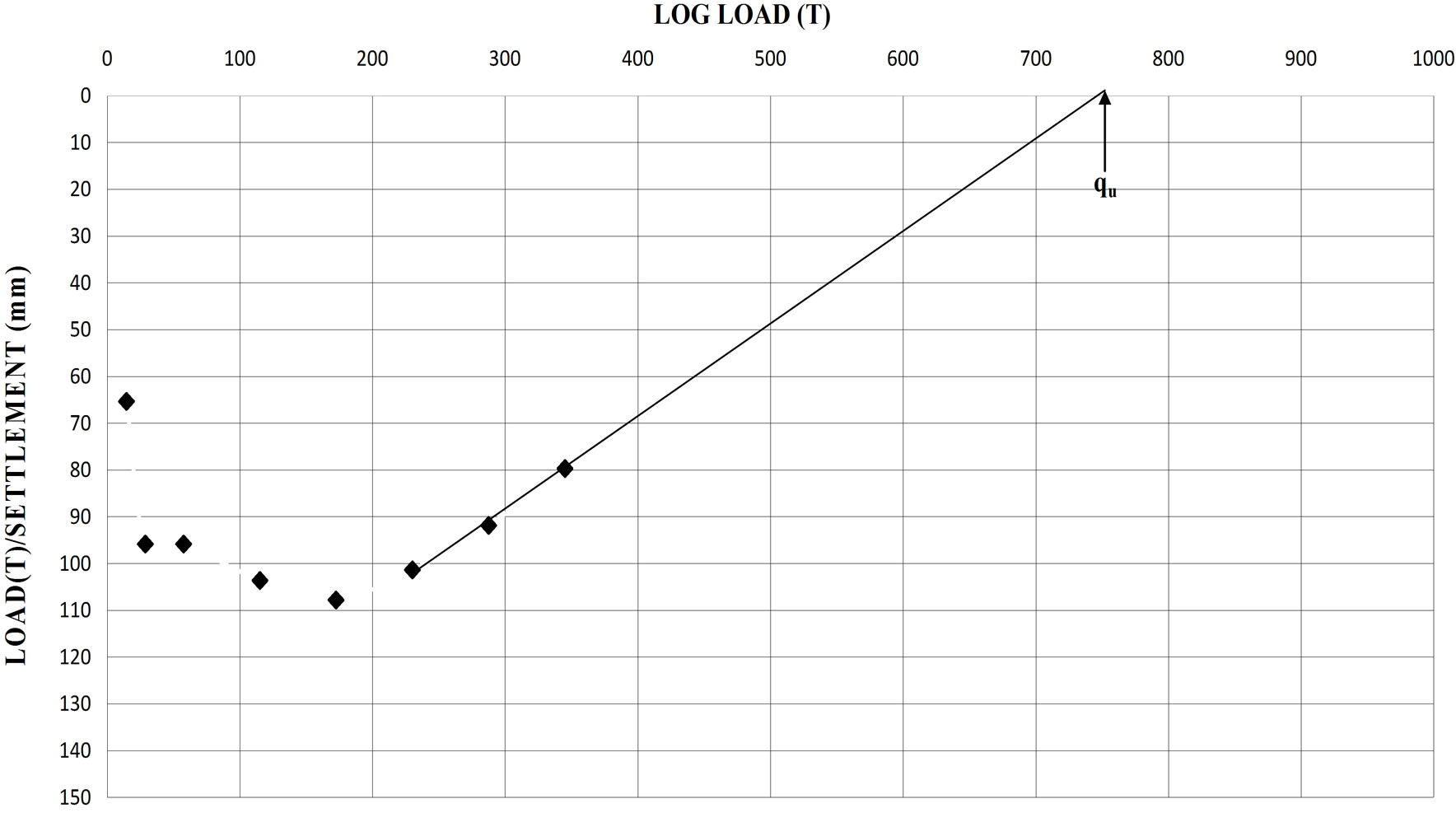
Figure 11. Ultimate pile capacities by Decourt’s extrapolation method for working test pile #3.
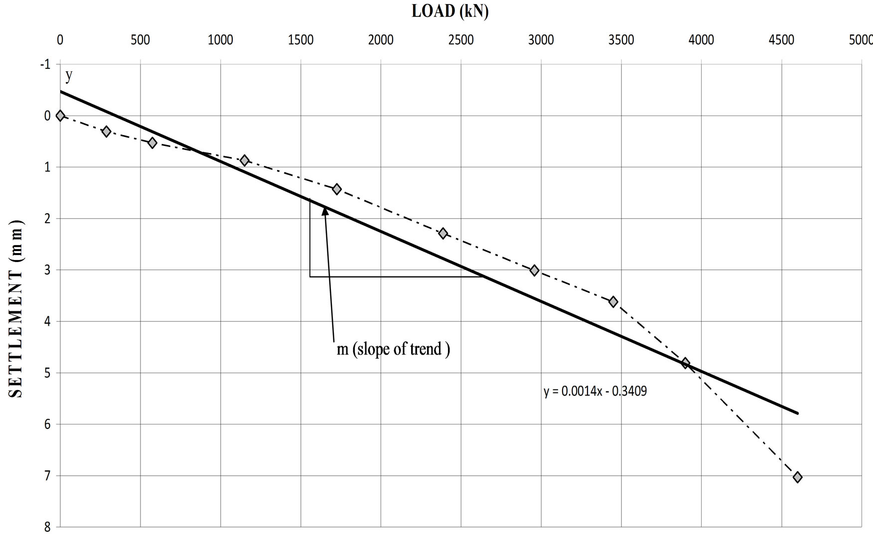
Figure 12. Ultimate pile capacity using proposed method for non-working test pile #1.
9. Conclusions
From the testing program and comparable study conducted, the following conclusions are arrived at:
1) The percentage of friction load carried by the shaft is approximately 85% to 90% and the percentage of load carried by the end bearing is 15% to 10%.
2) Hansen (1963) method gives higher values of ultimate capacity carried by the pile than the other methods.
3) A new proposed method to calculate the ultimate capacity of pile from pile load test is presented.
4) The proposed method for determining the ultimate capacity of friction piles appears to give results that are in good agreement with the analytical predictions.
5) The proposed method is good to apply, easier, quicker, more reliable, does not give max or min numbers as compared to some others.
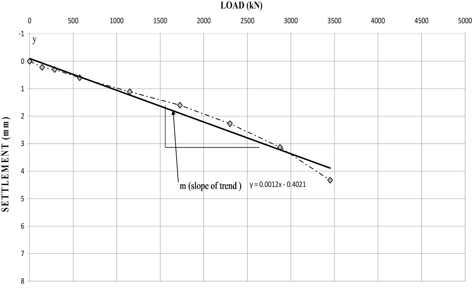
Figure 13. Ultimate pile capacity piles using proposed method for working test pile pile #2.
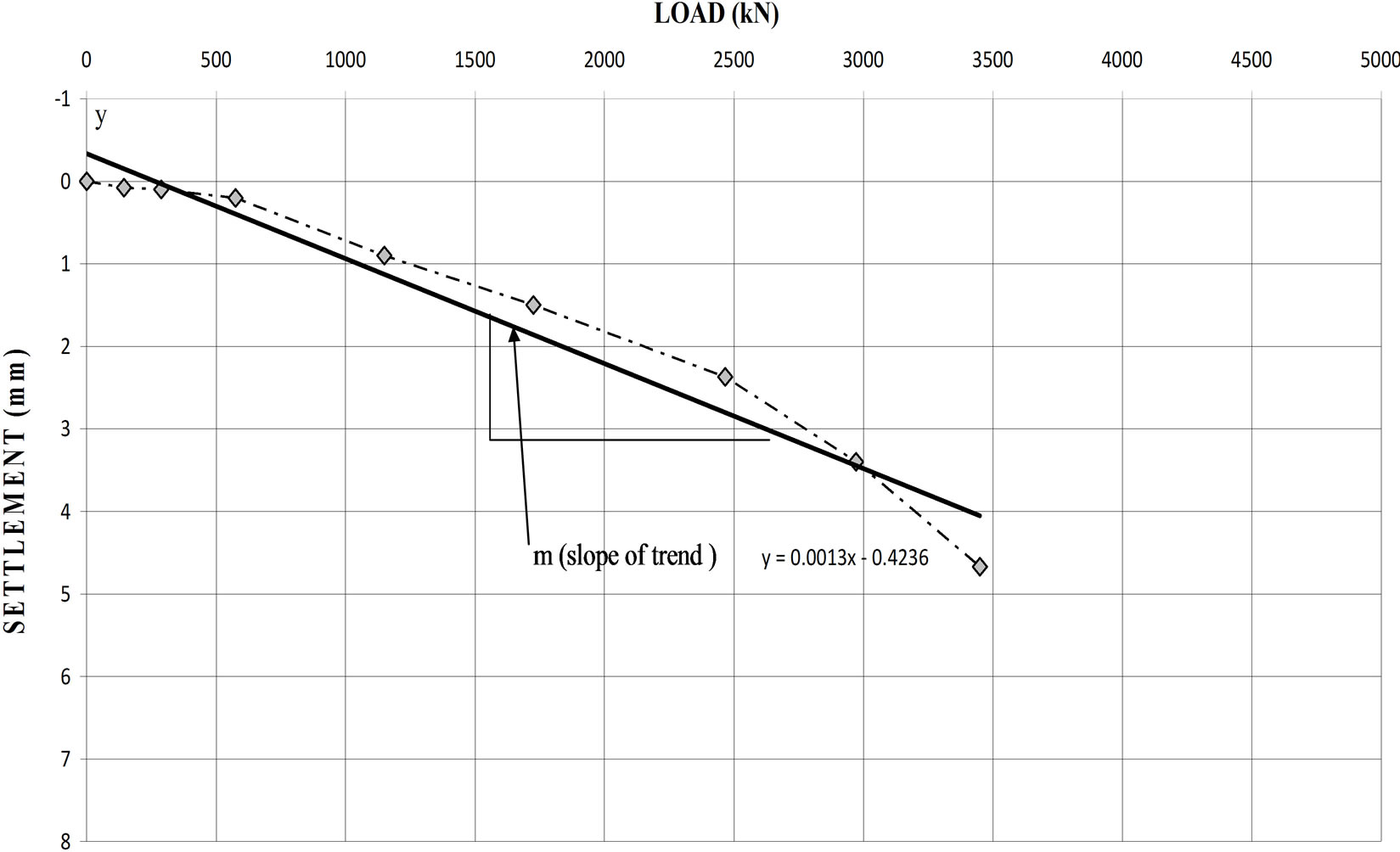
Figure 14. Ultimate pile capacity pile using proposed method for working test pile #3.
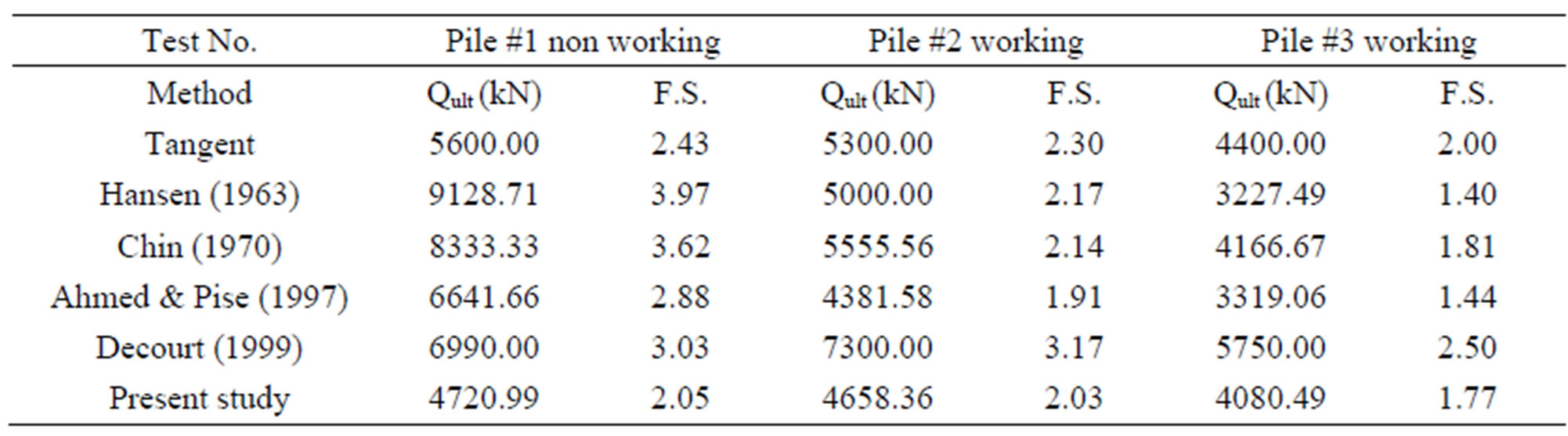
Table 5. Ultimate capacity and factor of safety (F.S.) of pile using different methods.
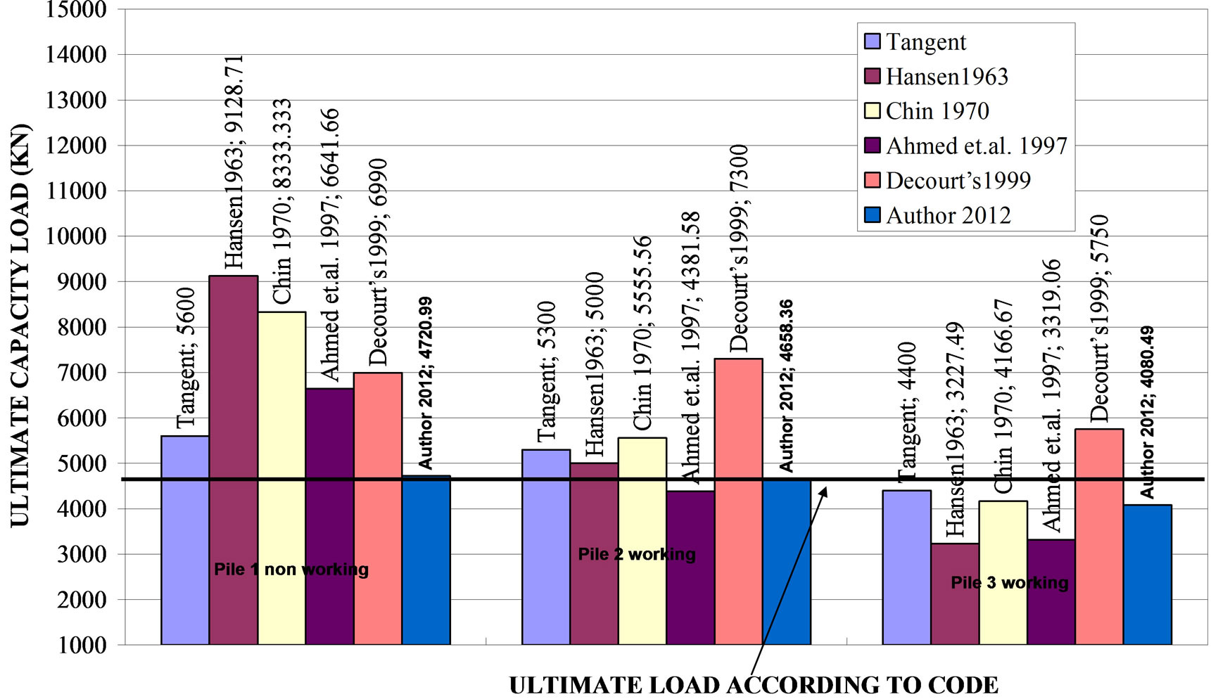
Figure 15. Comparison of ultimate pile loads using different methods.
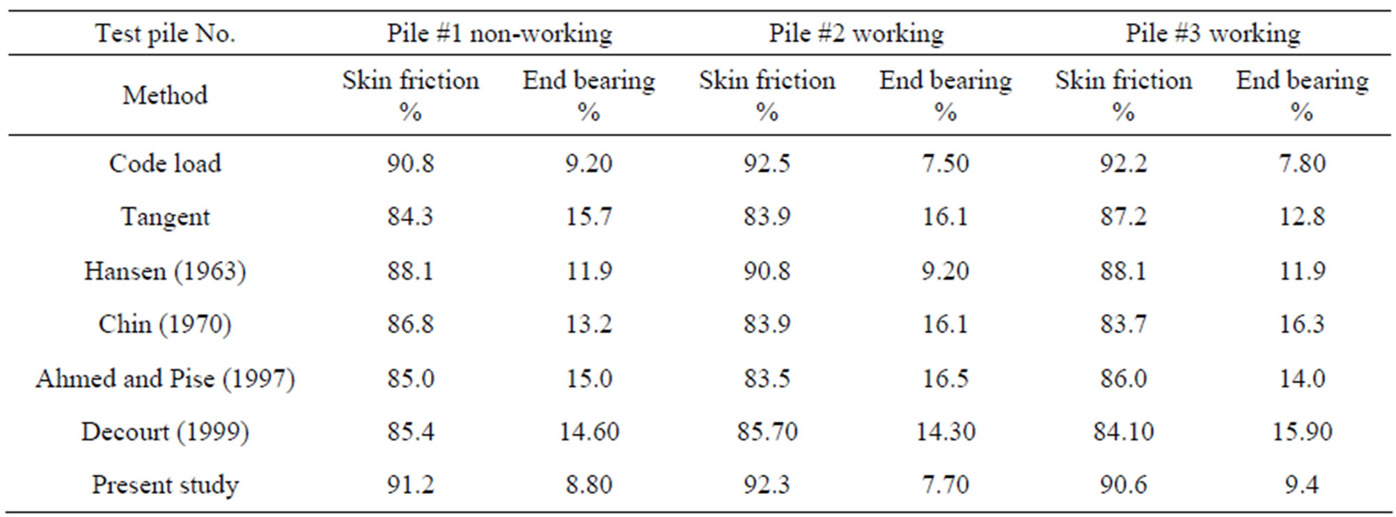
Table 6. Percentage of ultimate load carried by end bearing and friction.
10. Acknowledgements
The author would like to acknowledge the Fetih Construction Company and Pauer-Egypt Company for their valuable assistance.
REFERENCES
- U. A. A. Mirza, “Pile Skin Friction in Clays,” International Journal of Offshore and Polar Engineering, Vol. 7, No. 1, 1997, pp. 538-540.
- D. M. Dewaikar and M. J. Pallavi, “Analysis of Pile Load Tests Data,” Journal of Southeast Asian Geotechnical Society, Vol. 6, No. 4, 2000, pp. 27-39.
- F. I. Nabil, “Axial Load Tests on Bored Piles and Pile Groups in Cemented Sands,” Journal of Geotechnical and Geoenvironmental Engineering, Vol. 127, No. 9, 2001, pp. 766-733. doi:10.1061/(ASCE)1090-0241(2001)127:9(766)
- G. E. Abdelrahman, E. M. Shaarawi and K. S. Abouzaid, “Interpretation of Axial Pile Load Test Results for Continuous Flight Auger Piles,” Emerging Technologies in Structural Engineering, Proceedings of the 9th Arab Structural Engineering Conference, Abu Dhabi, 29 November- 1 December 2003, pp. 791-802.
- M. Wehnert and P. A. Vermeer, “Numerical Analysis of Load Test on Bored Piles,” Proceedings of the Ninth International Symposium on “Numerical Models in Geomechanics”, Ottawa, 25-27 August 2004, pp. 1-6.
- A. M. Radwan, A. H. Abdel-rahman, M. Rabie and M. F. Awad-Allah, “New Suggested Approach for Design of Large Diameter Bored Piles Based on Finite Element Analysis,” Twelfth International Colloquium on Structural and Geotechnical Engineering (12th ICSGE), 10-12 December 2007, Cairo, pp. 340-357.
- Egyptian Code, “Soil Mechanics and Foundation,” Organization, Cairo, 2005.
- A. Akbar, S. Khilji, S. B. Khan, M. S. Qureshi and M. Sattar, “Shaft Friction of Bored Piles in Hard Clay,” Pakistan Journal of Engineering and Applied Science, Vol. 3, 2008, pp. 54-60.
- H. H. Al Jairry, “Exact Probability Equation for Friction Piles in Clay,” Iraqi Journal of Civil Engineering, Vol. 6, No. 1, 2009, pp. 791-802.
- J. B. Hansen, “Discussion on Hyperbolic Stress-Strain Response, Cohesive Soils,” Journal for Soil Mechanics and Foundation Engineering, Vol. 89, 1963, pp. 241- 242.
- F. K. Chin, “Estimation of the Ultimate Load of Piles from Tests Not Carried to Failure,” Proceedings of Second Southeast Asian Conference on Soil Engineering, Singapore City, 11-15 June 1970, pp. 81-92.
- F. Ahmed and P. J. Pise, “Pile Load Test Data-Interpretation & Correlation Study,” Indian Geotechnical Conference, Vadodara, 17-20 December 1997, pp. 443-446.
- L. Decourt, “Behavior of Foundations under Working Load Conditions,” Proceedings of the 11th Pan-American Conference on Soil Mechanics and Geotechnical Engineering, Foz DoIguassu, August 1999, Vol. 4, pp. 453-488.