Engineering
Vol. 3 No. 12 (2011) , Article ID: 9214 , 12 pages DOI:10.4236/eng.2011.312151
Design and Development of a House-Mobile Security System
1Department of Mechanical Engineering, Faculty of Engineering, Taif University, Al-Haweiah, Saudi Arabia
2Tecnológico de Monterrey, Campus Ciudad Juárez, Parque Industrial Bermudez, Chihuahua, Mexico
E-mail: ashr12000@yahoo.com
Received October 19, 2011; revised November 1, 2011; accepted November 11, 2011
Keywords: Home Security, Alarm, Mobile, Low Cost, Design, Text Message
ABSTRACT
The objective of this work is to design, develop and implement an alarm system that triggers the alarm and alerts the owner via a mobile text message if the house has been opened or an attempt has been made to open it illegally. The system will also feature two different forms of activation/deactivation and will automatically open or close the door for the user. The advantages of this house-mobile security system (HMSS) are its high security level, robustness, low cost and ease of use (uncomplicated) and that there is no distance limitation for contact. The system integrates different sensors via a microcon-troller, which is the brain of the system, in order to avoid the problem of false alarms sent by other alarm monitoring systems to “Alarm Receiving Centers” or Police departments. The HMSS is useful in homes, small businesses, offices, warehouses, etc.
1. Introduction
The importance of home security has greatly increased in recent years. Let us consider the issue of security around our town of Ciudad Juarez, Mexico. Many houses are burgled mainly by means of illegal entry by force, such as breaking a window or slashing a screen or by entering through an unlocked door or an open window. Consequently, we have seen a trend in the increasing need for home security systems. Early studies have shown that burglaries seldom occur in places where an efficient, secure home security system has been installed [1].
Safety alarms are electronic alarms designed to alert the user of a specific danger. Sensors are connected to a control unit via low-voltage wiring or a narrowband radio frequency (RF) signal which is used to interact with a response device. The most common security sensors are used to indicate the opening of a door or window or to detect motion via passive infrared (PIR). Alarm systems often use wireless techniques for a faster and more economical installation. Some systems serve a single purpose of burglar or fire protection. Systems range from small, self-contained noisemakers, to complicated, multizoned systems with color-coded computer monitor outputs.
Today, home security system manufacturers and alarm monitoring services offer a variety of ways for users to monitor their home’s security system even when users are away from their home on vacation or simply away because of work. Modern alarm systems can notify owners of changes in their alarm system status by paging them. While these innovations are certainly useful and offer more peace of mind about home security, they are not the most exciting technologies used in many home security systems.
Many alarm monitoring services now allow users to access their home security system online via the Internet [2-4]. They can check the status of their system, and even view video in their home if they have installed surveillance cameras [5-7]. Very advanced alarm systems even allow users to change security codes, lockout security codes and arm or disarm the security system via a web interface. However, there is a new and very popular trend emerging in home security system monitoring mobile devices and telephones.
The integration of the mobile phone and a surveillance system becomes more meaningful so that people can monitor the security of their properties anytime, anywhere. People can access and manipulate uploaded pictures directly by Wireless Application Protocol (WAP) via a mobile phone [8]. They can use a gateway to enable the control of consumer electronics devices connected to the home network from a mobile phone; the gateway intermediates are wired between the home network and a wireless communication network using Home Audio Video interoperability (HAVi) and WAP specification, respectively [9]. Recently, a video clip system has developed a way to transfer the video stream to a mobile phone through Ethernet from PCs [10]. A new kind of wireless image system provides users with the image information by means of a multimedia message service (MMS) [11].
In this work, a practical house-mobile security system (HMSS) is designed and implemented. But why design a home security system when there are already a number of security systems widely available? While it is true that there are some high-quality security systems available, as mentioned earlier, a majority of homeowners, especially in Ciudad Juarez, simply cannot afford to pay for a professional security system. In addition, many homeowners may not feel the need to actually invest in those expensive security systems. On the other hand, most inexpensive home security devices and components are nothing more than cheap and ineffective noise makers. In such systems, false alarms are very frequent and many urbanites tend to ignore alarms rather than investigate, i.e., there may be no response at all. The aim of this work is to fill this gap by presenting a system with a high security level and a low cost. The HMSS solves the problem related to the false alarms found in other systems by integrating different sensors into one unique system. This system is planned to work at a high security level, and is robust, low-cost, uncomplicated, and has no distance limitation. The system is designed to avoid the entry of possible intruders into the house and to alert the owner via a mobile phone text message. It is inexpensive and useful in homes, small businesses, offices, warehouses, etc.
2. System Design
The House Mobile Security System (HMSS) consists of mechanical, electrical, and electronic compon-ents, which are integrated to complete the system design, as follows.
2.1. Vibration Sensor
An AK-CGQtype vibration detector alarm sensor is mounted on barriers and used to detect an attack on the structure itself (door/window). This vibration sensor works based on an unstable mechanical configuration that forms part of the electrical circuit. When movement or vibration occurs, the unstable portion of the circuit moves and breaks the current flow, which produces an alarm. The technology of the sensor varies and can be sensitive to different levels of vibration. The suitable sensitivity of the sensor must be correctly selected based on the working environment as they are best suited to different types of structures and configurations. Figure 1 shows the vibration sensor and its detailed characteristics are presented in Table 1.
2.2. Magnetic Sensor
The magnetic sensor includes two strips, one attached to the door and the other to the door frame. A relay switch, in the sensor, is connected to the strips within a wire, as shown in Figure 2. The relay switch is held down to show a “closed” circuit when the two magnetic metal strips touch each other. Once one strip moves away from the other, the circuit is opened and the switch pushes up into the signaling wire. That wire alerts the controller that the circuit is open and then the controller triggers an alarm. The magnetic sensor we used, type DS10A, selfchecks every 90 minutes and is capable of sending radio frequency (RF) signals to any home security system’s base receiver. The sensor uses standard AA batteries to provide up to 1 year of operation.

Figure 1. Vibration detector alarm sensor AK-CGQ.

Table 1. Characteristics of the vibration sensor (AK-CGQ).
2.3. DC Motor
The main function is to open and close the door/window/gates for the user. The DC motor, as shown in Figure 3, provides the conversion of microcontroller signals to mechanical actions. The full detailed characteristics of the DC motor are presented in Table 2 below. This motor was chosen because its speed and torque characteristics were best suited for our application.
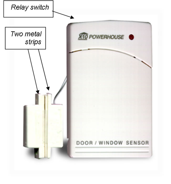
Figure 2. Magnetic sensor.

Figure 3. DC motor.
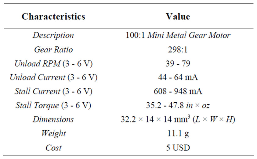
Table 2. Characteristics of DC motor.
2.4. Numeric Keypad
Normally, alarm systems are deactivated or reconfigured when authorized personnel are present. Authorization may be indicated in a number of ways, often with keys or codes used at the control panel or a remote panel near an entry. High-security alarms may require multiple codes, or a fingerprint, badge, hand-geometry, retinal scan, encrypted response generator, and other means that are deemed sufficiently secure for the purpose. Failed authorizations result in an alarm and a timed lockout to prevent “experimenting” with possible codes. In this system, we used a numeric keypad with a USB host interface, as shown in Figure 4.
2.5. Relay Receiver Board
A relay receiver board, as shown in Figure 5, provides independently programmable control for each of the onboard relays. Relay outputs are used to automatically turn sensors and system devices On/Off. The software interface is compatible with Windows 7/Vista/XP/ME/ 2000/NT/9x and allows users to program and save an infinite number of On/Off sequences. Each relay output is capable of switching resistive loads of up to 1 Amp @ 45 Vac/70 Vdc max and has an LED to indicate its status. The detailed characteristics of the relay receiver board are presented in Table 3 and details of the work are shown in Figure 6.
2.6. Power Supply
A power supply with the following features, as shown in Figure 7, is needed for our system.
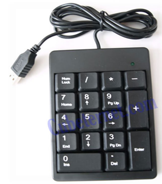
Figure 4. Numeric keypad lenovo group limited.

Figure 5. Relay receiver board with remote control.
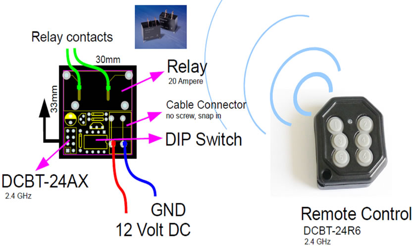
Figure 6. Detailed characteristics of the relay receiver board with remote control.

Figure 7. Power supply with adapter transformer.
2.7. Motorola C168i Model Mobile Phone
The Motorola C168i mobile phone, as shown in Figure 8, is used for receiving the alarm message. There is a possibility of sending the alarm message to more than one mobile phone. The features of our mobile phone are presented in Table 4.
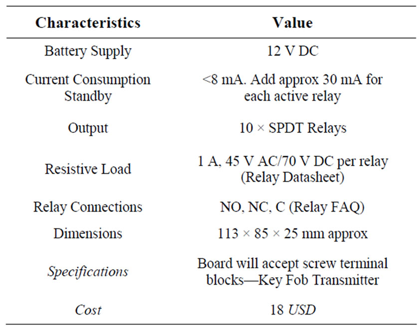
Table 3. Characteristics of the relay receiver board.
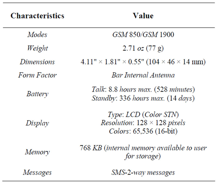
Table 4. Features of motorola c168i model.
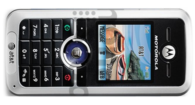
Figure 8. Motorola c168i model mobile phone.
2.8. Microcontroller ATMEL 168
The microcontroller is the “brain” of the entire system and provides the calculations needed to control all the actions taken. Since this microcontroller is “open hardware”, there are no licensing or copyright issues [12].
The microcontroller used is an Atmega 368 which comes with a development/programming board named “Arduino”, as shown in Figure 9. The programming language is very similar to C but includes several libraryies that help in the control of the I/O ports, timers, and serial communication. This microcontroller was chosen because of its low price, ease of reprogramming and simple programming language, and, in addition, interrupts are available for this particular chip. Features of the microcontroller are shown in Table 5.
2.9. Housing
The last part of the design is the housing for the system. After all the mechanical, electrical, and electronic equipments were defined, the device was assembled in a firm housing to guarantee the security system and its functionality. The housing design comprises a high-resistance structure that holds the components well. The housing with the complete prototype of the integrated system is shown in Figure 10.
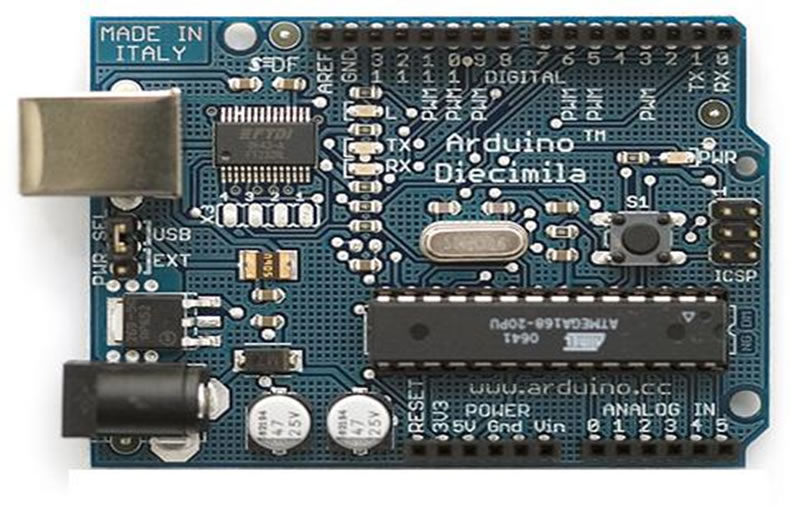
Figure 9. Arduino microcontroller board.
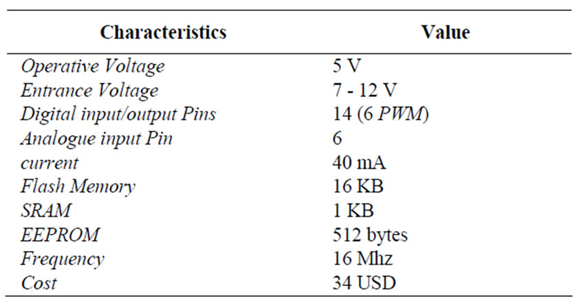
Table 5. Features of microcontroller ATMEL 168.
2.10. Software Design
As system consists of a hard ware and software, the detailed code of software code is presented in appendix. However, software of different components is presented within system operation and development section in this paper.
3. Testing and Validation
We considered testing to be a very important part of this work and placed emphasis on conducting it meticulously. Several tests were carried out to validate the HMSS and its components. The tests covered both the particular elements and the overall system. Firstly all components were tested individually to demonstrate their capability of working properly. After words, the overall system is tested. Since we have three working modules, as described in the next section, we tested these modules using the black-box testing methodology, which involved sending inputs into the module, measuring the outputs and comparing them with the expected outputs. We are not concerned with what happens inside the module.
After each module was completely tested and debugged, the vibration sensor position was tested by placing it in different positions on the door. This test was carried out to determine the best sensing position for detecting vibrations or blows in the event of someone trying to open the door. We placed the sensor in three different locations, top, next to lock and center, and tested the vibration results in each case, as shown in
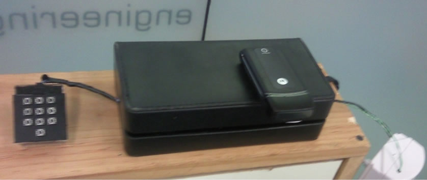
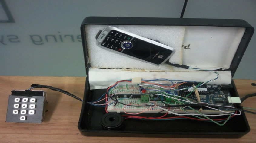
Figure 10. HMSS housing.
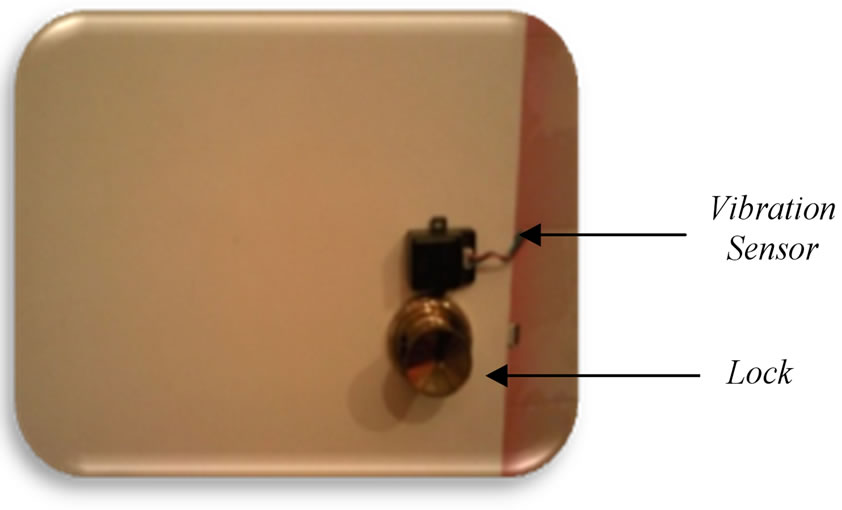
Figure 11. The sensitivity to vibration was low when the sensor was in the next to door position. However, it was high when the sensor was in the top of door position. In the center of door position, the sensitivity was medium, as shown in Table 6. We decided to place the vibration sensor in the center position so that the sensor will detect when someone is trying to open the door and avoid the false alarm in the top position, e.g., a visitor knocking on the door or windy days, or the lower sensitivity in the next to lock position. Figure 12 shows the final positions of the vibration and magnetic sensors attached to the door.
 (a)
(a)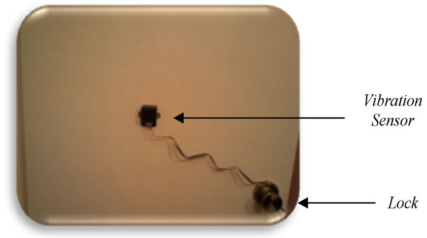 (b)
(b)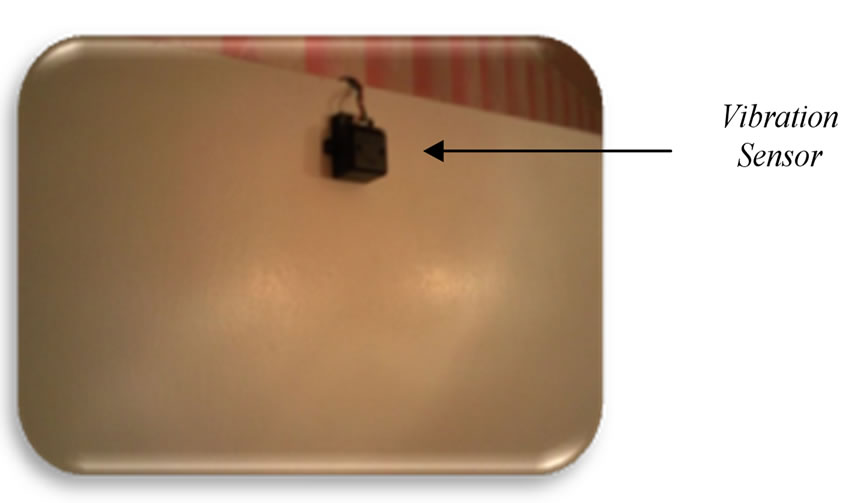 (c)
(c)
Figure 11. Testing different positions for the vibration sensor at: (a) next to lock; (b) center, and (c) top of door.
4. System Operation and Development
The system operation interface is shown in Figure 13 and the system operation flowchart is presented in Figure 14. As shown in Figure 14, the system contains three different modules. In Module 1, the system will send a message to the user’s mobile when someone attempts to open the door or when the door has already been opened without the correct password on the keypad or signal by remote control.
In Module 2, the system will lock or unlock the door via remote control. In Module 3, the system will lock or unlock the door by entering a 4 digit password. In short, the door will be opened normally in 2 ways: with the correct password entered on the keypad or with the remote control. It is important to note that it is not necessary to activate both of the systems to unlock the door. The three system operation modules are summarized in Table 7 and then discussed in detail.
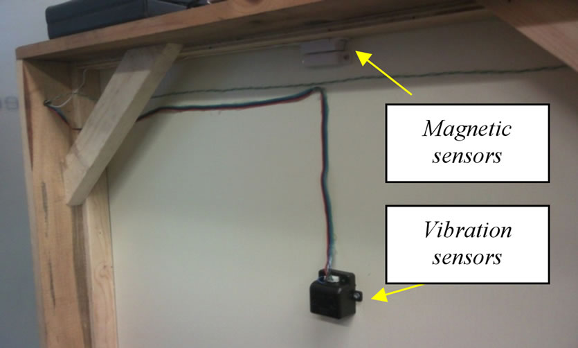
Figure 12. Final position of vibration and magnetic sensors.

Table 6. Vibration sensitivity with the sensor in 3 different locations on the door.

Table 7. Three different working modules of HMSS.
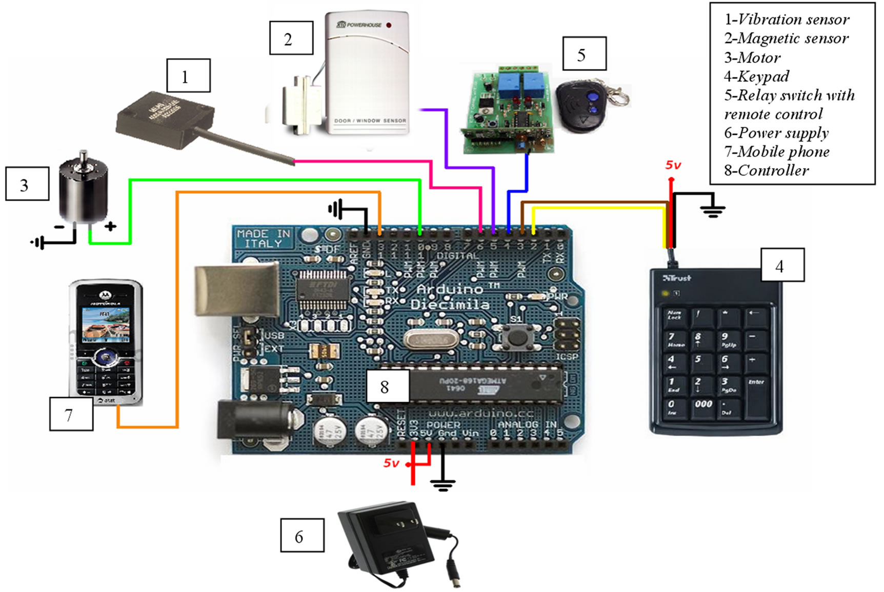
Figure 13. HMSS operation interface.
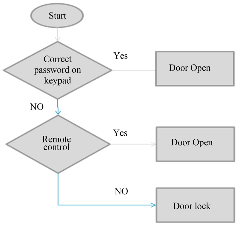
Figure 14. System operation flowchart.
4.1. Module 1: Text Message Sending
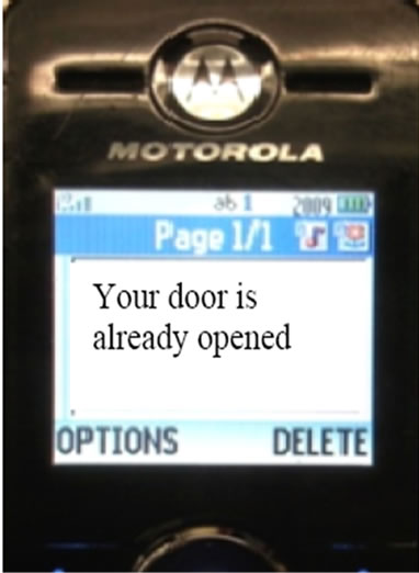
The basic function of Module 1 is to send a message to the user’s mobile device when someone is attempting to open the door or when it has already been opened incurrectly, e.g., without the correct password on the keypad or the remote signal. If somebody is trying to open the door, message number 1 will be sent, “Someone is attempting to open your door”, as shown in Figure 15. When the system detects that the door is opened, message 2 will be sent by the magnetic sensor, “Your door is already opened”; in addition, the magnetic sensor will trigger an alarm signal.
The program enables interaction between the microcontroller and the mobile phone and sending the messages in Module 1 is presented in Table 8 with brief explanations for each command. This program sets specific commands for the Motorola C168i, however, it should work with other phones or only need minor changes.
For the vibration sensor, which is an analog input to the controller, we defined the correct parameter as the value of “40”. So, if the signal of the sensor is larger or equal to 40, the message will be sent and the program will be as follows.
buttonState1 = analogRead (senialVibracion);
delay (200);
if (buttonState1 >= 40 && a! = HIGH) {
mensaje1();}
 (a)
(a) (b)
(b)
Figure 15. Messages sent to mobile if (a) someone is attempting to open the door; (b) the door has already been opened.
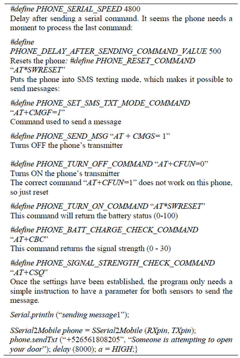
Table 8. Program interact the microcontroller with the cell phone and sending messages in Module 1 with brief explanations for each command.
This value was carefully defined because we just want to sense rough movements or aggressive knocks on the door to avoid false alarms, for example when somebody knocks normally the door. In addition, the program defined a variable to allow a message to be sent only in a determinate time. This is to avoid sending several messages for each second during which somebody is trying to open the door.
For the magnetic sensor, the structure of the program was easier since the magnetic sensor gives a digital input and therefore we just needed to define the text to send the message where the program is as follows:
buttonState2 = digitalRead (senialMagnetico);
delay (200);
if (buttonState2 == LOW) {mensaje2();}
In the magnetic sensor, once the message has been sent, we apply some delay for sending a new message. This is because if somebody gets into the house, he/she will probably leave the door open and, therefore, without message delaying, the message would be sent over and over again.
4.2. Module 2: Lock/Unlock the Door via Remote control
This module is related to the action taken by the remote control. The remote control normally sends a signal to the main controller to activate/deactivate the alarm and also to open or close the door. It was necessary to assign variables for the different states of the door and the remote control. The signals assigned, as shown in Table 9, include four cases:
■ C1—Door closed, alarm not activated.
■ C2—Door closed, alarm activated.
■ C3—Door open, alarm not activated.
■ C4—Door open, alarm activated, message sent.
Since the remote signal is only 1 or 0 (HIGH or LOW), the controller will have an instruction to do nothing before the first “1” given by the user, meaning that the alarm has been activated and then keeps working to detect the next deactivation and so on. With this signal, the remote control will activate the mechanism that opens the door, as shown in Figure 16. The different conditions for the remote signals are:
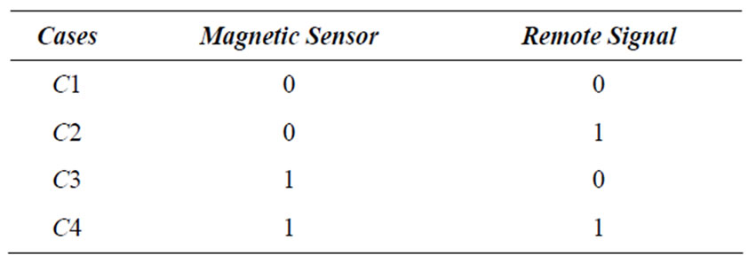
Table 9. Signals assigned in module 2.
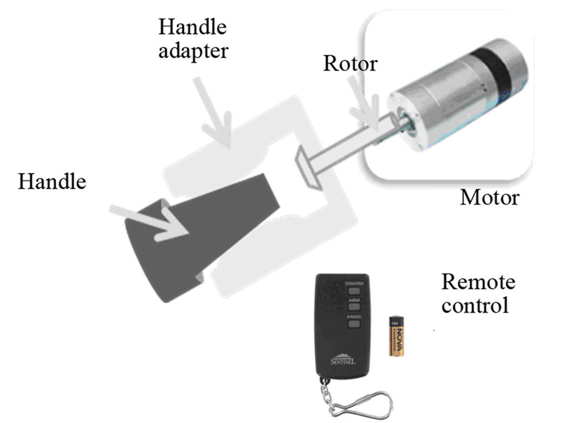
Figure 16. Scenario of lock/unlock the door via remote control.

Table 10. Cost of HMSS (excluding the mobil phone).
■ 0—Alarm not activated (On Reset).
■ 1—Alarm activation. Open/Close mechanism CLOSED.
■ 0—Alarm deactivation. Open/Close mechanism OPEN.
Once the signal has been received, it only needs to be defined in the program as a digital input. The program is simply:
const int senialInalambrica = 4;
pinMode (senialInalambrica, INPUT);
4.3. Module 3: Lock/Unlock the Door by Introducing a 4 Digit Password
This module deals with developing a numeric keypad with a USB host interface, as shown in Figure 4. The keypad is connected to the HMSS via a microcontroller, as shown in Figure 13, and in turn allows the user to activate or deactivate the alarm system via a 4 digit password. The keypad, as remote control in module 2, sends a signal to the main controller to activate/deactivate the alarm and also to open or close the door. Correct authorization allows to deactivate the alarm and to open the door; however, failed authorizations result in an alarm and a timed lockout to prevent “experimenting” with possible codes.
During the programming of the microcontroller to acquire the signal from the keypad, we faced some problems with the ports since the controller could not detect the signal from the PS/2 converter because we had a USB numeric keypad. Therefore, we had to design one using common circuits such as flip-flops and a relay to read the password from the keypad.
In a very high-security system demand, HMSS is designed to be flexible to implement multiple codes, fingerprints, badge, hand-geometry, retinal scan, encrypted response generator, and other means that are deemed sufficiently secure for the purpose.
We improved our HMSS by adding a small buzzer that gives different sound signals when different actions are occurring in the program; specifically, when the program is started, when the door is opened and when the door is closed. We used musical chords to implement these sounds.
Although the HMSS is tested within the range of Cuidad Juarez city (area of 2 million populations), we expect that it will work for larger range (no distance limitation) based on the system monitoring-mobile devices and telephones technology. The integration of the mobile phone and a surveillance system becomes more meaningful so that people can examine the security of their properties anytime, anywhere.
The cost of different components of HMSS and the whole cost of the system is summarized in Table 10. Compared with other systems, the total cost of our system is very low, about 110 USD excluding the mobile phone. By this low cost, high security level, robust, and uncomplicated design system, many homeowners, especially in Ciudad Juarez, may be come to a decision to invest in the security systems. Currently, as mentioned earlier, a majority of homeowners, especially in Ciudad Juarez, cannot afford to pay for a professional expensive security system and they are unconvinced with currently ineffective low cost systems; however, with our new system, we wish we succeeded to provide their needs.
5. Conclusions
This work presents a house-mobile security system (HMSS) that is able to dial out to a preprogrammed mobile phone number and send a message when the system’s sensor detector is triggered. This system is a great device that will provide a sense of security for any homeowner, small business, office, warehouse, etc. The advantages of this system are its high security level, robustness, low cost, ease of use (uncomplicated) and that there is no distance limitation for contact. The system integrates different sensors via a microcontroller to avoid the problem of false alarms sent by other alarm monitoring systems. The system will also feature two different forms of activation/deactivation and will automatically open or close the door for the user. HMSS is flexible to implement multiple codes, fingerprints, badge, handgeometry, retinal scan, and/or other means that are deemed sufficiently secure for the purpose.
6. REFERENCES
- Cognigen Networks, Inc., “Cognigen Completes Acquisition of Commission River,” 2007. http://cognigen.net.
- K. Y. Kong, C. Y. Ng and K. Ong, “Web-Based Monitoring of Real-Time ECG Data,” Computers in Cardiology 2000, Cambridge, 2000, pp. 189-192.
- A. I. Hernandez, F. Mora, M. Villegas, G. Passariello and G. Carrault, “Real-Time ECG Transmission via Internet for Nonclinical Applications,” IEEE Transactions on Information Technology in Biomedicine, Vol. 5, No. 3, 2001, pp. 253-257.
- F. Lamberti and C. Demartini, “Low-Cost Home Monitoring Using a Java-Based Embedded Computer,” IEEE EMBS Conference on Information Technology Applications in Biomedicine, Lamberti, 24-26 April 2003, pp. 342-345.
- Y. Shirai, J. Miuar, Y Mae, M. Shiohara, H. Egawa and S. Sasaki, “Moving Object Perception and Tracking by Use of DSP,” Proceedings of Computer Architectures for Machine Perception, Roma, 3-5 November 1993, pp. 251- 256.
- P. Mahonen, “Wireless Video Surveillance: System Concepts,” Proceedings of International Conference on Image Analysis and Processing, Venice, 29 September 1999, pp. 1090-1095. doi:10.1109/ICIAP.1999.797745
- K. Sato, B. L. Evans and J. K. Aggarwal, “Designing an Embedded Video Processing Camera Using a 16-Bit Microprocessor for Surveillance System,” Proceedings of DCV Work on Digital and Computational Video, Clearwater, 14-15 November 2002, pp. 151-158.
- P. M. Corcoran, P. Bigioi and E. Steinberg, “Wireless Transfer of Image from a Standard GSM Mobile Phone,” IEEE Transactions on Consumer Electronics, Vol. 47, No. 3, 2001, pp. 542-547. doi:10.1109/30.964144
- M. Nikolova, F. Meijs and P. Voorwinden, “Remote Mobile Control of Home Appliances,” IEEE Transactions on Consumer Electronics, Vol. 49, No. 1, 2003, pp. 123-127. doi:10.1109/TCE.2003.1205464
- “Ugolive,” 2011. http://www.ugolive.com/Browser/default.asp
- “NOKIA,” 2011. http://www.nokia.com/research/observation_camera_demo/index.html
- “Arduino,” 2011. http://www.arduino.cc
Appendix
#include
#include
#define RXpin 10 // Celular Azul (salida)
#define TXpin 11 // Celular Verde (salida)
const int analogOutPin = 9; // PWM driver (salida)
int motor_a1 = 3; // AIN1 (salida)
int motor_a2 = 2; // AIN2 (salida)
const int senialVibracion = 3; // sensor vibracion (entrada analoga)
const int senialInalambrica = 4; // sensor inalambrico (entrada analoga)
int keypad = 5; // keypad (entrada digital)
int speakerPin = 7; // buzzer (salida)
int senialMagnetico = 6; // sensor magnetico
(entrada digital)
int returnVal=10; // celular
int buttonState = 0; // Lee status de boton/inalambrico
int buttonState1 = 0; // Lee status de vibracion
int buttonState2 = 0; // Lee status de magnetico
int buttonState3 = 0; // Lee status de keypad
int a =0; //solo mande un mensaje 1
int x =0; //leen estado boton/inalambrico
int y =0; //leen estado keypad
int z =0; //lee cambio keypad/inalambrico
//-------------------------------------------void setup()
{pinMode(senialInalambrica, INPUT);
pinMode(senialVibracion, INPUT);
pinMode(keypad, INPUT);
pinMode(senialMagnetico, INPUT);
pinMode(speakerPin, OUTPUT);
Serial.begin(9600);
Serial.println(“HOUSE MOBILE ALARM”); delay (500);
Serial.println(“Inicio”); delay (700);
Serial.print(“.”); delay (700);
Serial.print(“.”); delay (700);
Serial.println(“.”); delay (1000);
startupSound();}
//------------------------------------------void loop(){
delay (500);
buttonState = analogRead(senialInalambrica);
buttonState2 = digitalRead(senialMagnetico);
buttonState3 = digitalRead(keypad);
Serial.print(buttonState, DEC);
Serial.print(" and ");
Serial.print(buttonState3, DEC);
Serial.print(" and ");
Serial.println(buttonState2, DEC);
delay(500);
if (buttonState >= 300 && buttonState2 == HIGH || buttonState3 == HIGH && buttonState2 == HIGH ) {//valores de sensor inalambrico y magnetico openSound();
if (buttonState >=300){x=HIGH; z=x;}
else { x=LOW; z=x;}
cerrarPuerta();}//activa el sistema
else{ delay(500); }}
void cerrarPuerta(){
y = buttonState3;
Serial.println("Closing Door");
digitalWrite(motor_a1,LOW);
digitalWrite(motor_a2,HIGH);
analogWrite(analogOutPin,150);
delay(1000);//tiempo del motor cerrando
digitalWrite(motor_a1,LOW);
digitalWrite(motor_a2,LOW);
analogWrite(analogOutPin,0);
delay(500);
while (z == x && buttonState3 == y){
delay (100);
buttonState = analogRead(senialInalambrica);
if (x==HIGH && buttonState <300){ z =!z;}
else {
if (x==LOW && buttonState >=300){ z=!z;}}
buttonState3 = digitalRead(keypad);
Serial.print(“Wireless:”);
Serial.println(buttonState, DEC);
Serial.print(“Keypad:”);
Serial.println(buttonState3, DEC);
delay (500);
buttonState1 = analogRead(senialVibracion);
Serial.print(“Vibration sen:”);
Serial.println(buttonState1, DEC);
delay(200);
if (buttonState1 >= 40 && a != HIGH) {
mensaje1();}
buttonState2 = digitalRead (senialMagnetico);
Serial.print(“Magnetic sen:”);
Serial.println(buttonState2, DEC);
delay(200);
if (buttonState2 == LOW) {
mensaje2();}}
//void abrirPuerta()
Serial.println(“Opening Door”);
closeSound();
y = buttonState3;
a = LOW;
digitalWrite(motor_a1,HIGH);
digitalWrite(motor_a2,LOW);
analogWrite(analogOutPin,150);
delay(400);//tiempo del motor al abrir
digitalWrite(motor_a1,LOW);
digitalWrite(motor_a2,LOW);
analogWrite(analogOutPin,0);
delay(500);
while (!z == x && buttonState3 == y && buttonState2 == HIGH){//valores de s.inalambrico
buttonState = analogRead (senialInalambrica);
if (x==HIGH && buttonState >=900){ z=!z;}
else {
if (x==LOW && buttonState <900){ z=!z;} }
buttonState2 = digitalRead (senialMagnetico);
buttonState3 = digitalRead (keypad);
Serial.print(“Wireless:”);
Serial.print(buttonState, DEC);
Serial.print(“ and Keypad:”);
Serial.print(buttonState3, DEC);
Serial.print(“ and Magnetic:”);
Serial.println(buttonState2, DEC);
delay (500);}}
void mensaje1 (){
Serial.println (“sending message1”);
SSerial2Mobile phone = SSerial2Mobile(RXpin,TXpin);
phone.sendTxt(“+526561808205”, “Someone is attempting to open your door”);
delay(8000);
a = HIGH;}
void mensaje2 (){
Serial.println(“sending message2”);
SSerial2Mobile phone = SSerial2Mobile(RXpin,TXpin);
phone.sendTxt(“+526561808205”, “Your door has been opened”);
delay(30000);}
void openSound(){int n = 300;
for (int vez=0;vez<3;vez++){
for (int _=0;_<100;_++){
delayMicroseconds(n);
digitalWrite(speakerPin, HIGH);
delayMicroseconds(n);
digitalWrite(speakerPin, LOW);}
delay(100);}}
void closeSound(){int n = 300;
for (int vez=0;vez<2;vez++){
for (int _=0;_<100;_++){
delayMicroseconds(n);
digitalWrite(speakerPin, HIGH);
delayMicroseconds(n);
digitalWrite(speakerPin, LOW);}
delay(100);}
n = 450;
for (int _=0;_<110;_++){
delayMicroseconds(n);
digitalWrite(speakerPin, HIGH);
delayMicroseconds(n);
digitalWrite(speakerPin, LOW);}}
void startupSound(){//RE MI DO DO. SOL
int note = (1/587.33)*500000;
for (int _=0;_<100000/note;_++){
delayMicroseconds(note);
digitalWrite(speakerPin, HIGH);
delayMicroseconds(note);
digitalWrite(speakerPin, LOW);}
note = (1/659.26)*500000;
for (int _=0;_<100000/note;_++){
delayMicroseconds(note);
digitalWrite(speakerPin, HIGH);
delayMicroseconds(note);
digitalWrite(speakerPin, LOW);}
note = (1/523.25)*500000;
for (int _=0;_<100000/note;_++){
delayMicroseconds(note);
digitalWrite(speakerPin, HIGH);
delayMicroseconds(note);
digitalWrite(speakerPin, LOW);}
note = (1/261.63)*500000;
for (int _=0;_<100000/note;_++){
delayMicroseconds(note);
digitalWrite(speakerPin, HIGH);
delayMicroseconds(note);
digitalWrite(speakerPin, LOW);}
note = (1/392.00)*500000;
for (int _=0;_<200000/note;_++){
delayMicroseconds(note);
digitalWrite(speakerPin, HIGH);
delayMicroseconds(note);
digitalWrite(speakerPin, LOW);}}

