Engineering
Vol. 3 No. 7 (2011) , Article ID: 6255 , 7 pages DOI:10.4236/eng.2011.37089
Development of Roller Ends Forced-Contact Model and Cambering Technology for UCM Temper Mill (II)
1School of Mechanical Engineering, State Key Laboratory of Metastable Materials Science and Technology, Yanshan University, Qinhuang Island, China
2Thin Strip Co., Ltd., Baoshan Iron & Steel Co., Ltd., Shanghai, China
E-mail: bai_zhenhua@yahoo.com.cn, {sihongxin, xiaodong_shi}@126.com
Received April 18, 2011; revised May 18, 2011; accepted May 25, 2011
Keywords: UCM, Temper Mill, Forced-Contact, Roll Shape, Roll Consumption
ABSTRACT
Roller ends forced-contact and overmuch roll consumption are the widespread problems in temper rolling process of thin strip for two-stand UCM temper mill. Fully thinking the equipment and technology characteristics of UCM temper mill, we took the newly-built 1220 UCM temper mill of Baosteel as the research object in this paper. A model of roller ends forced-contact and a calculation model of flatness for UCM temper mill are established after a great deal of site tracing and theoretical researches. On this basis, an optimal mathematical model of roll shape which is suited for UCM temper mill is developed. Working roll curve is the combination of cosine curve and high order curve. The cosine subentry is used to control edge wave, the high order curve subentry is used to control roller ends forced-contact. Furthermore, the chamfering curve of middle roller end is optimized. Those are the innovations. Through the above-mentioned technology, pressure distribution between rollers caused by the shift of middle roll becomes more homogen-eous, pressure peak disappeared, working life of roll is improved effectively as well. Relevant technologies have been used to the practice of 1220 UCM temper mill of Baosteel and have achieved good use effects, which is of further extending application value.
1. Development of Cambering Technology for UCM Temper Mill
1.1. Target of Cambering
The intermediate roll should have proper shift for improving strip shape in the process of temper rolling. But the shift of intermediate roll will make the pressure distribution between rollers more uneven. Peak distribution will appear and cause uneven abrasion of rollers. Strip shape and surface quality will become worse. Roll consumption will increase sharply. In addition, the contact of working rolls outside the plate width will appear when thin and narrow strip is temper rolled. The forced-contact of working rolls will lead to that partial presetting rolling force is used to metal deformation and others cause the roller ends squashed which lead to the actual elongation is smaller than design value. The product performance does not meet the user needs. Working roll consumption will increase accordingly. Due to the requirements of customers for strip mechanical performance, strip shape and surface quality become higher and higher and the cost for rollers compressed constantly as well, the problems above are bottleneck problems and the focus of technology research in the temper rolling process of thin and narrow strip. Therefore, the newly-built 1220 UCM temper mill of Baosteel is taken as a research object, a model of roller ends forced-contact and a computational model of flatness which is suited for UCM temper mill have been established after lots of field tracing and theoretical research. The following three targets are realized through the optimizing design of roll configuration: 1) good flatness of rolled strip; 2) without forced-contact of working rolls; 3) The pressure distribution between rollers caused by the shift of middle roll become more homogeneous. Side effects such as peak are disappeared. Working life of roll is improved effectively [1].
1.2. Development of Cambering Model for UCM Temper Mill
From the metal deformation model, the strip shape of the first and second stand in exit can be expressed with the following formulas for two-stand UCM temper mill:
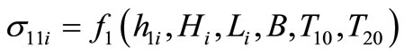 (31)
(31)
 (32)
(32)
where ,
,  are the transverse distribution value of strip exit thickness in the first and the second stand,
  is the transverse distribution value of strip entry thickness,
  is the transverse distribution value of length and used to express the incoming profile, B is the width of strip.
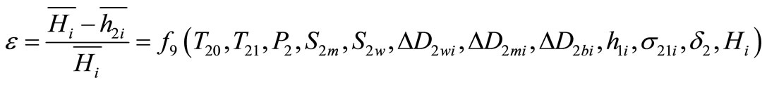
Similarly, from the model for elastic deformation of rolls mentioned in 2.2, the transverse distribution value of strip exit thickness in the first and second stand ,
,  , the pressure between rollers
 ,
,  ,
,  ,
,  and elongation
  can be expressed with the following formulas [2]:
 (33)
(33)
 (34)
(34)
 (35)
(35)
 (36)
(36)
 (37)
(37)
 (38)
(38)
 (39)
(39)
where  and
and  are the pressure between intermediate roll and working roll in the first and the second stand;
  and
and  are the pressure between intermediate roll and back-up roll in the first and the second stand;
 ,
,  ,
,  and
and  are the bending force of working roll and intermediate roll in the first and the second stand;
 ,
,  and
and  are the roll configuration distribution value of working roll, intermediate roll and back-up roll in the first stand;
 ,
,  and
and  are the roll configuration distribution value of working roll, intermediate roll and back-up roll in the second stand;
  and
and  are the intermediate roll’s shift value of the first and the second stand;
 ,
,  and
and  are the back tension, middle tension and front tension;
  and
and  are the total rolling force of the first and the second stand.
During the optimizing process of cambering, if the actual datas of  and
and  existed, then the actual datas should be used. Or the distribution of incoming crown can be considered as conic and proportion crown can be considered as 0.01 as a rule of thumb; the incoming profile is good and the value of
  is zero. The back-up roll can be considered as plain barrelled roll, that is to say the value of
  and
and  are all zero. And then, after a simple analysis, for a specific rolling process of two-stand UCM temper mill, on condition that the back-up roll is plain barrelled roll, if the rolling craft parameters
  , the bending force of working roll and intermediate roll and the shift value of intermediate
  etc. are given,
  the transverse distribution value of front tension in exit,
  the transverse distribution value of pressure between rollers,
  the elongation can be expressed with roll profile parameters of working roll and intermediate roll uniformly after coupling Equation (31) to Equation (39).
 (40)
(40)
 (41)
(41)
 (42)
(42)
 (43)
(43)
 (44)
(44)
 (45)
(45)
It should be noted that the pressure between intermediate roll and working roll and the pressure between intermediate roll and back-up roll in the first stand have nothing with the working roll shape and intermediate roll shape of the second stand. For the convenience of expression, the form of Equations (37) and (38) are similar to Equations (39) and (40)
Actually, according to the production characteristics of two-stand UCM temper mill, the working roll configuration curves and back-up roll configuration curves of two stands are often designed to the same curve. And then, Equations (40) to (45) as follows:
 (46)
(46)
 (47)
(47)
 (48)
(48)
 (49)
(49)
 (50)
(50)
 (51)
(51)
Based on field experiments and theoretical research, shown as Figure 3, the form of working roll configuration curve is shown in the following Equation (52) [3]:
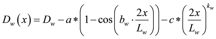 (52)
(52)
where  is the original working roll diameter,
  is the face length of working roll,
  is the crown value,
  is the cosine phase coefficient of working roll configuration curve, c is subentry coefficient of working roll’s high order curve,
  is subentry index of working roll’s high order curve.
In Equation (52), the cosine subentry is used to control edge wave, the high order curve subentry is used to control roll forced-contact. Obviously, it is easy to describe working roll configuration curve shown in Figure 3 and Equation (52) if  are given.
Allow for the actual working ability of grinder, in practice, the intermediate roll configuration curve can be expressed with the following Equation (53) (as shown in Figure 4):
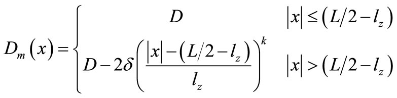 (54)
(54)
where  is the original diameter of intermediate roll,
  is the face length of intermediate roll.
So, relevant roll profile parameters can be expressed with , therefore, Equations (46) to (51) can be expressed with Equations (55) to (60) further.
 (55)
(55)

Figure 3. The Schematic diagram of working roll curve.
Figure 4. The Schematic diagram of intermediate roll curve.
 (56)
(56)
 (57)
(57)
 (58)
(58)
 (59)
(59)
 (60)
(60)
In this way, on condition that the parameters of mental deformation model and roller system model such as rolling force and tension etc. are known, the optimizing objective function of working roll profile and intermediate roll profile can be expressed with the following formulas for a single specification product and the equipment and production craft characters of UCM temper mill [4]:
 (61)
(61)
where  is weighting coefficient,
  is the minimum elongation ruled by product program.
 is objective function of shape control,
 ,
,
 is overall objective function of pressure between rollers:
 .
.
 is control objective function of pressure between intermediate roll and working roll in the first stand,
 .
.
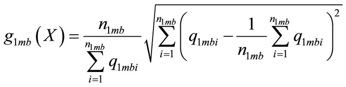
 is the indicator function of pressure’s degree of uniformity between intermediate roll and working roll in the first stand,
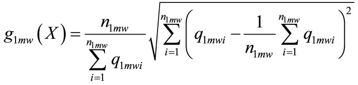 .
.
 is the indicator function of peak pressure between intermediate roll and working roll in the first stand,
 .
.
 is the target function of pressure control between intermediate roll and back-up roll in the first stand,
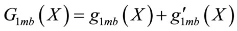 .
.
 the indicator function of pressure’s degree of uniformity between intermediate roll and back-up roll in the first stand,
 .
.
 is the indicator function of peak pressure between intermediate roll and back-up roll in the first stand,
 .
.
 is the target function of pressure control between intermediate roll and working roll in the second stand,
 .
.
 is the indicator function of pressure’s degree of uniformity between intermediate roll and working roll in the second stand [5],
 .
.
 is the indicator function of peak pressure between intermediate roll and working roll in the second stand,
 .
.
 is the target function of pressure control between intermediate roll and back-up roll in the second stand,
 .
.
 is the indicator function of pressure’s degree of uniformity between intermediate roll and back-up roll in the second stand,
 .
.
 is the indicator function of peak pressure between intermediate roll and back-up roll in the second stand,
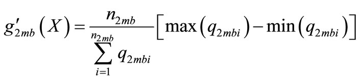 .
.
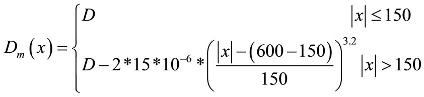
where  is allowable transverse maximum peak value between rolls,
  is number of transverse strip element,
  is number of strip element between intermediate roll and working roll in the first stand,
  is number of strip element between intermediate roll and back-up roll in the first stand,
  is number of strip element between intermediate roll and working roll in the second stand,
  is number of strip element between intermediate roll and back-up roll in the second stand.
Obviously, the optimal setting of working roll configuration curve and intermediate roll configuration curve is aimed at improving strip shape quality and managing roll forced-contact at the same time, making the pressure distribution between rollers become more homogeneous, reducing the peak value of pressure between rolls, improving working life of rollers. It should be noted that production site, in practical, often m kinds of specifications are choosed for optimization, and according to the portion of total amount to weight, the more often produced the product is, the weighting coefficient is more larger. So, the objective control function for the optimization of roll contour can be expressed as follows [6]:
 (62)
(62)
where  is weighted coefficient of output, which is depend on the portion of each specification output share in all output.
So, the comprehensive optimization of working roll configuration curve and intermediate roll configuration curve translate into seeking a suitable roll configuration curve parameters , which minimizes
 .
.
1.3. Application of Cambering Model in UCM Temper Mill
Working roll, intermediate roll and back-up roll are all flat roll at the beginning of putting into production of the newly-built 1220 UCM temper mill of Baosteel. The phenomenons which Elongation does not reach the standard and strip shape is unqualified were often found in production. In order to solve the shape and mechanical property problems, relevant theories introduced in 3.2 are applied at the base of Section 2 and the working roll and back-up roll configuration curves are optimized. Moreover, the new roll shape has been put into field operation in 2010, a significant effect have been received. Not only the strip shape has guaranteed, but also the mechanical property has the users’ request. At present, this roll shape has been adopted regularly by field as process planning. Relevant circumstances are introduced in details as follows:
1.3.1. Cambering Scheme of 1220 Two-Stand UCM Temper Mill
Based on calculations, working roll adopts the roll configuration curve illustrated in Equation (63), intermediate roll adopts the roll configuration curve illustrated in Equation (64), back-up roll adopts flat roll [7].
 (63)
(63)
 (64)
(64)
1.3.2. Introduction for Test Results of Field Comparison
To further analyses the roll shape reconstruction effect of the newly-built 1220 two-stand UCM temper mill of Baosteel, as a contrast, take the second stand as the example, working roll and intermediate roll adopt the roll configuration curve illustrated in Equations (63) and (64) respectively, back-up roll adopts flat roll. 0.15 × 718 mm was choosed as specimen to do the forced-contact test (related equipments and process parameters as shown in the following Table 1). The value of contact width, actual rolling force and strip shape before and after roll crown optimization were given though test. After the forced-contact test, the production of this specification proceeded with the elongation of 1.0% until roll changing. The length of rolling this moment was recorded in the following Table 3. The value of the indicator function of pressure’s degree of uniformity and the indicator function of peak pressure are computed as well, shown in the following Table 4 [8].
It can be seen from Table 3 that the roll forced-contact has been controlled effectively after roll shape was optimized. Slight roll forced-contact just appeared at the elongation of 1.2% (this moment, the product mechanical property has meet the users’ demand). When elongation increased to 0.4%, the roller ends forced-contact just appeared if original roll shape was adopted, and with the increase of elongation, the roller ends forced-contact become worse and worse, normal rolling was affected at last. In addition, it can be seen clearly from Table 3 that the shape quality of strip improved greatly, measured maximum strip shape decreased apparently, the length of rolling increased greatly. Last, it can be seen from Table 3 that both the value of the indicator function of pressure’s degree of uniformity and the value of the indicator function of peak pressure decreased greatly. Combining Tables 3 and 4, it can be seen through field contrast tests that expected targets such as the control of roll forced-contact, the improvement of shape quality and the reducing of roll consumption all achieved.
2. Conclusions
Roller ends forced-contact and overmuch roll consumption exist in the rolling process of two-stand UCM temper mill. Fully thinking the equipment and production craft characters of UCM temper mill, a model of roller
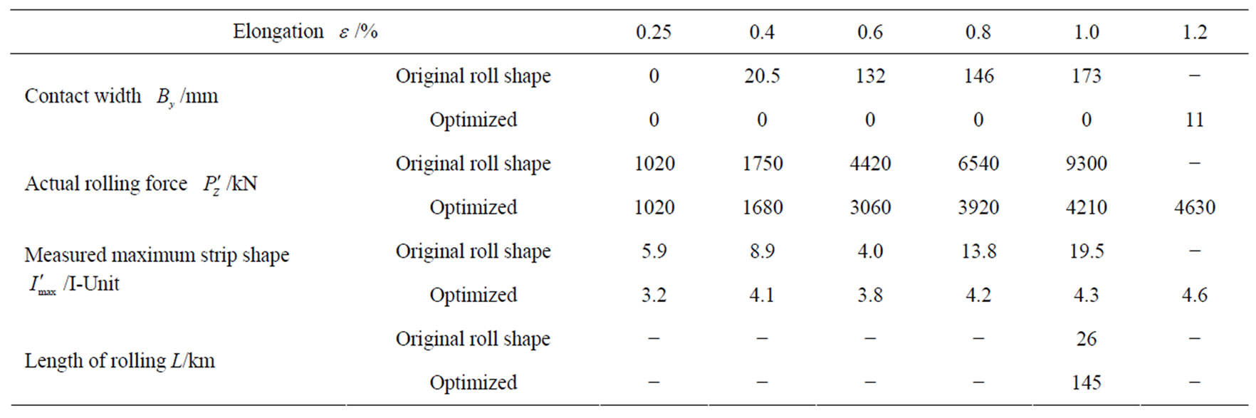
Table 3. The value of contact width, actual rolling force and strip shape before and after roll crown optimization.
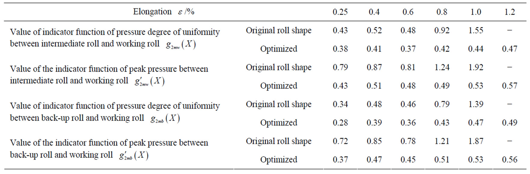
Table 4. Contrast of the indicator function of pressure’s degree of uniformity and the indicator function of peak pressure before and after roll crown optimization.
ends forced-contact and a computational model of flatness which is suited for UCM temper mill is established after lots of field tracing and theoretical research. Moreover, on the basis of this, starting with the roll crown optimization of working rolls and intermediate rolls, strip shape, roll consumption and the management of roll forced-contact are considered as well. A mathematical model of roll crown optimization which is suited for the working rolls and intermediate rolls of UCM temper mill is developed. Relevant technologies have been used to the practice of 1220 UCM temper mill of Baosteel. The pressure distribution between rollers caused by the shift of middle roll becomes more homogeneous. Side effects such as peak are disappeared. Working life of roll is improved effectively. This technology has achieved good use effects, which is of further extending application value.
3. Acknowledgements
Contract/grant sponsor and Grant Number:
1) Contract/grant sponsor: Hundred Excellent Researchers Award Program of Department of Education of Hebei Province. Grant Number: CPRC018.
2) Contract/grant sponsor: Natural Science Foundation of Hebei Province (Surface Project). Grant Number: E2011203019.
3) Contract/grant sponsor: Natural Science Foundation of Hebei Province (Base Special Fund). Grant Number: 08B015.
4. REFERENCES
- Z. H. Bai, “Development and Research of Shape Control Technology about Skin Mill,” Doctoral Dissertations, Yanshan University, Qinhuang Island, 2002.
- J. C. Lian and H. M. Liu, “Guage and Shape Control,” Weapon Industry Press, Beijing, 1995.
- Z. H. Bai, X. P. Kang and R. B. Long, “Practical Temper Rolling Force Model and Its Self Study Technology,” Steel, Vol. 43, No. 10, 2008, pp. 51-54.
- Z. H. Bai, Y. F. Jiang and X. D. Li, “Kiss between Roller Ends in Skin Rolling Process of Super Thin Strip,” Chinese Journal of Mechanical Engineering, Vol. 42, No. 8, 2006, pp. 224-228. doi:10.3901/JME.2006.08.224
- Z. H. Bai and J. Yang, “Research on Shape Technique for Baosteel Planishing Mill,” Bao-Steel Technology, Vol. 1, 2003, pp. 48-51.
- Z. H. Bai, “Calculating Model of Rolling Parameters of Two-Stand Planishing Mill,” Journal of Iron and Steel Research, Vol. 18, No. 9, 2006, pp. 29-31.
- Z. H. Bai, X. P. Kang and S. M. Wu, “Shape Parameters Online Setting of Two-Stand UCM Temper Mill,” Steel, Vol. 44, No. 5, 2009, pp. 39-43.
- Z. H. Bai, J. C. Lian, F. Liu and J. Q. Wang, “Research of the Roll Crown Optimization on Skin Pass Mill in Baosteel 2050 Hot Rolling Plant,” Steel, Vol. 37, No. 9, 2002, pp. 35-38.