Materials Sciences and Applications
Vol. 3 No. 12 (2012) , Article ID: 25534 , 7 pages DOI:10.4236/msa.2012.312129
Physical and Morphological Structure of Chicken Feathers (Keratin Biofiber) in Natural, Chemically and Thermally Modified Forms
![]()
1Post-Graduate Program in Mechanical Engineering, Federal University of Rio Grande do Norte, Natal, Brazil; 2Post-Graduate Program in Chemistry, Federal University of Rio Grande do Norte, Natal, Brazil.
Email: rasiah@ufrnet.br/debelarmino@yahoo.com.br
Received September 19th, 2012; revised October 16th, 2012; accepted November 17th, 2012
Keywords: Feather; Keratin; Carbon; Structure; Microparticles; Nanoparticles
ABSTRACT
Because of the constant challenge to preserve the environment and the search for new materials, a comparative study was carried out using keratin fiber, a fibrous protein, found in the chicken feathers. Five different samples of the feather were analyzed by Scanning Electron Microscopy (SEM) and X-ray diffractometer (XRD). First in their natural form Keratin Fiber (KF); the second treated with sodium hydroxide (KFNaOH); the third and fourth samples were semi carbonized at 220˚C in an oven without atmospheric control for 24 hours (samples obtained: Clear brown (SCFC) and Dark brown (SCFD)); and the fifth sample was carbonized by pyrolysis Carbonized Feathers (CF). The SEM result shows that the KF has a hollow structure, with knots and hooks. The KFNaOH structure presented rougher than that of the KF, but lost their hooks. The SCFC and SCFD presented brittle structures, but preserved the hollow structure of KF; however, it was only noticeable to a magnification of 3000 times. On the other hand, the CF, was shiny, black, and showed a higher amount of porosity with open micro-pores and micro-tubes, preserved the hollow structure of KF than any other samples studied, and also presented well-defined closed micro-tubes. From the XRD analysis of the KF, CF, KFNaOH, SCFC and SCFD, presented semi-crystalline structures, with the following indices of crystallinity, 20.09%, 18.93%, 17.97%, 15.02% and 14.31%, respectively. The CF presented smaller size crystallites, in between the microparticulates, around 27 nm and the KFNaOH with larger size around 74 nm. From this study it was concluded that micro-porous carbon material from chicken feathers (KF) could be efficiently obtained through pyrolysis.
1. Introduction
The demand by the society and the environment, especially in times of global warming, in recent years the search for the materials of low weight and relatively low cost, durable, and well supplied, is increasing, as good parts of the materials in use are from resources with decreasing availability, nonrenewable and high cost. The fiber of chicken feathers, primarily made up of three separate units. A central axis (rachis with up to 7 cm in length) that are attached to the calamus, the secondary structures (bards from 1 to 4.5 cm depending on its location in the rachis, for example near the base are longer than in the tip) (Figure 1). In a similar manner, the third structure (barbules with length between 0.3 - 0.5 mm) is connected to the barbs and has hooks in its ends, which are best viewed by Scanning Electron Microscopy (SEM) (Figure 2) [1].
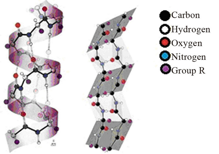
The feather is composed of about 90% of keratin, which has a structure characteristic of materials of high mechanical strength [2,3]. The keratin has α-helix and β-pleated sheet structure (Figure 3), comprising about
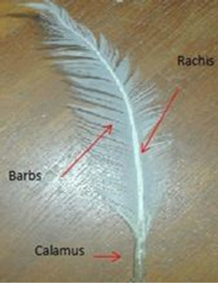
Figure 1. Photograph of a chicken feather showing, calamus, rachis and barbs.
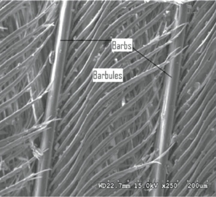
Figure 2. Micrograph of the secondary and tertiary structure of the chicken feather showing barbs and barbules [1].
 (a) (b)
Figure 3. (a) α-helix and (b) β-pleated Sheet structure [5].
20 amino acids, mainly of cysteine and its structure consists of a central carbon linked to functional groups (amine, -NH2, and carboxylic acid, -COOH), the hydrogen atoms and the group R (sulfur) [4].
The feathers are sources of natural, renewable, lowcost and hollow structure, which characterizes its lowdensity (0.8 g/cm3) compared with wool (1.3 g/cm3) and cellulose fibers (1.5 g/cm3) and act as thermal insulators. They possess high flexibility and are hydrophobic, where their structure has high-carbon content. In addition to all these features, it is fibrous, has good compressibility and resiliency, when used in textile products, films and composites [1,2]. Due the length of the chicken feathers, they cannot be processed in textile machinery; however, the feathers need of suitable process for the manufacture of yarns and cloths, in 100% form or mixed with other materials, whether natural or synthetics [1,3].
Besides, they can be modified to improve their properties, by chemical treatment or subjected during the process of “slow pyrolysis” which is one of the heat treatments to obtain carbon under controlled atmosphere, time and temperature, and during the pyrolysis carbonaceous material releases volatile components. Remembering that these organic substances are a waste, which returned to the environment in the form of CO2 [6].
The protein keratin when heated forms cross-links, while strengthening its structure, it becomes more porous, thus increasing its surface area. The cycle of pyrolysis needed to be performed at the temperature ranges between 400˚C - 500˚C, and the temperature selected for pyrolysis should be kept constant in the nonoxidizing atmosphere. The carbonaceous material goes through gradual heating, which follows physical and chemical phenomena that generate the development of a solid residue concentrated in carbon and a gaseous part. Above 400˚C, release of H2 with the breaking up of the C=C and C-H groups occur. In an oxidative atmosphere, there is a loss of mass is higher at temperatures below 300˚C compared to a controlled atmosphere. Above 300˚C the thermal degradation occurs independently of an oxidative atmosphere, however in an inert atmosphere this process is mitigated [7,8].
The carbon has applications in the form of coke for the steel and iron industries. It furthermore, applies in industry of printing inks; paper, plastics, paint, manufacturing of carbon brushes for engines and as an insulator, among other applications. From of the carbon can be made tubular microstructures (with graphene layers perfectly arranged and wrapped), and its unique properties of carbon fibers have expanded the science and technology of composite materials in recent decades. The carbon fiber and its variant of smaller size (carbon nanofibers) are among the short carbon fibers that have attracted much attention, due to its properties, such as thermal, electrical, frequency shielding, and mechanical. They are increasingly being used for different systems of materials, such as composites, thanks to their exceptional properties and low cost [9-11].
Therefore, it is necessary to determine experimentally the various parameters, which reflect the efficiency of new materials obtained by characterizations of different techniques. Among them the microstructure analysis, which can be performed by SEM, because it allows greater visualization of the microstructure of the material and the mineralogical analysis by X-ray diffraction (XRD), which is the most indicated to determine the crystalline phases in materials, mainly due to its reliability of the results [12].
2. Materials and Methods
2.1. Materials
The raw material used were chicken feathers Keratin Fiber (KF), originated from the poultry industry located in the city of Natal/RN-Brazil, representing zero costs. All the other samples were prepared using the feathers, according to the methodology in reference [13]. By chemical treatment with a 2% aqueous solution of sodium hydroxide (KFNaOH) and subsequently washed to remove any traces of NaOH. And by termic treatments: semicarbonized in conventional oven without control atmospheric, at 220˚C for 24 hours, causing different colors, clear brown (SCFC) and dark brown (SCFD) and carbonized by pyrolysis in tubular furnace, under flow of argon, in temperatures of 220˚C for 24 h, and 450˚C for one hour, creating a homogeneous material, black and bright (CF) (Figure 4).
All the samples were characterized by the techniques: SEM and XRD, for comparative study and determining the efficiency of the proposed study.
2.2. Morphological Structure
Whole feather in its natural, crushed and modified forms were morphologically analyzed by SEMat the Nucleus for Studies in Petroleum and Gas (NEPGN) of UFRN which isfinanced by projects CTPETRO-INFRA, FINEP/ LIEM. The equipment used was the XL-30-ESEM, brand: PHILIPS.
2.3. Mineralogical Analysis
The mineralogical analysis was performed by XRD, by the dust method, to identify the crystalline phases at the Center of Technologies of Gas and Renewable Energy (CTGas-ER). The equipment used was the XRD-600 brand: SHIMADZU. The scanning was made between the angles 2θ (θ—Bragg’s angle of diffraction) = 5 - 80, using the radiation of CuKα with γ 1.5418 Å and speed of 2/min and step of 0.02˚.
The parameters: Theta (angle of incidence), d (spacing between the parallel planes, in angstroms) of the peaks of crystallinity of the samples were identified by software (X’Pert High Score) to measure the diameters (D) of the crystallites in each peak, by the relation of Scherrer, Equation (1). Where, K—constant which depends on the shape of the particles (sphere or when it is not known = 0.94 or 0.9), λ—wavelength of X-ray, emissions of the Cu tubes (λ = 1.54 Å), θ, β (2θ) —width at half the height of the diffraction peak in radians [14,15].
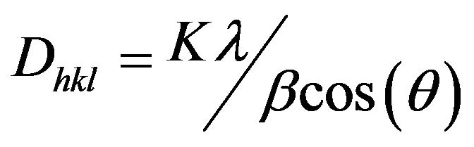 (1)
(1)
3. Results and Discussions
3.1. Morphological Structure
The morphological characteristics of the samples are shown in Figures 5-7. The crushed KF remains intact, a structure with knots and hooks, comparing with the whole KF (Figures 5(a) and (b)) [16].
The KFNaOH, lost their hooks and presented a rougher surface whichis characteristic of increased porosity in relation to the KF, Figure 5(c).
The oxidized and irregular particles, Figure 6(a), SCFC and SCFD, presented the similar morphological structure, although they have different colorations. A brittle structure was observed with fragments adhered to its surface, with cracks, protein degradation, which is due to oxidation of the material, and formation of overlapping layers, Figures 6(b)-(d). The hollow structure of KF was preserved, however, is only noticeable to a magnification of 3000 times, Figures 6(c) and (d).
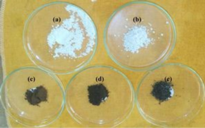
Figure 4. (a) KF; (b) KFNaOH; (c) SCFC; (d) SCFD; (e) CF.
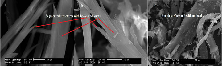
Figure 5. Micrographs. (a) Whole KF; (b) Crushed; and (c) KFNaOH.
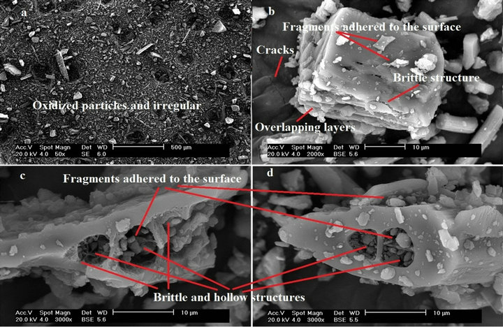
Figure 6. Micrographs of (a) SCFC at 50; (b) SCFD at 2000; (c) SCFC with 3000; and (d) SCFD at 3000× magnification.
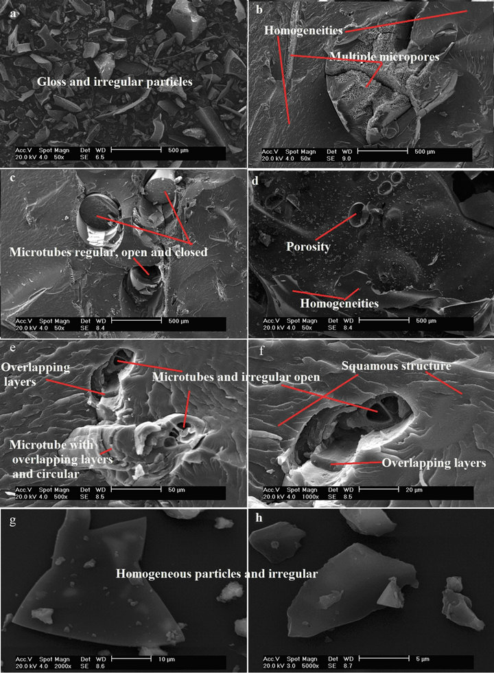
Figure 7. Micrographs of CF (a), (b), (c) and (d) in 50 and (e), (f), (g) and (h) in 500, 1000, 2000 and 5000, magnification respectively.
It is possible to observe, Figure 7, the shiny particles of CF with different sizes, homogeneous parts. Increase in porosity is observed, which represents crystalline regions or the removal of chemical elements of the original structure, with multiple micro-pores with diameters apparently regular and small, Figure 7(b). It was observed in Figure 7(c), that the CF shows habitual, open and unopen micro-tubes. The un-open micro-tubes of smaller sizes make the difference, in relation to other samples, because confer greater resistance [16].
In Figures 7(d)-(h), it has seen that the micrographs of CF in magnifications of 50, 500, 1000, 2000 and 5000×, respectively to a better view of the microstructures, which in addition to preserve, in some regions, the integrity of hollow axes of KF, with open micro-tubes uneven or not presented a scaly structure, overlapping layers, overlapping tubes and circular and uneven and homogeneous particles.
By comparing the particle size of all the samples, the micrographs show, that they have equivalent sizes in micrometers, for example, for a magnification of 2000 times, Figures 5(a) and (b), 6(b) and 7(g), they have a size of 10 micrometers, and are considered particulate reinforcements [17].
3.2. Mineralogical Analysis
The KF (Figure 8(a)) exhibits three narrow peaks around 2θ = 38˚, 64˚ and 77˚, which corresponds to the interplaynary spacings of 2.38231 Å, 1.44719 Å and 1.23161 Å, and relative intensity (%) of 9.97%, 43.12% and 50.54% respectively, related to 100% of crystallinity to peak 4˚, that besides being narrow, it is the most intense, around 44˚, which corresponds to the interplanary spacing of 2.05916. These effects are caused by the presence of crystalline regions within the sample. However, the existence of the reflection band around 2θ =10˚ and 20˚, clearly shows that the material may have an amorphous region.
For the KFNaOH, it was observed that the characteristic peaks of the KF around 2θ = 44˚, 64˚ and 77˚ are preserved, but its intensities are reduced, Figure 8(b), indicating a reduction in the crystallinity (compared with Figure 8(a)).
Already the diffraction of SCFC and SCFD, show that the KF loses its crystalline regions, presenting 2 peaks and 3 peaks of very short intensity, respectively, found around 64˚ and 77˚ to the SCFC and around 44˚, 64˚ and 77˚ to the SCFD. Being evidenced amorphous phases with the existence of reflection band in positions around 2θ = 20˚, which demonstrates that the materials may have amorphous phases in almost its entirety, Figures 8(c) and (d).
Figure 8(e) shows that the diffractograms of CF, where the diffraction patterns are similar to KF. However
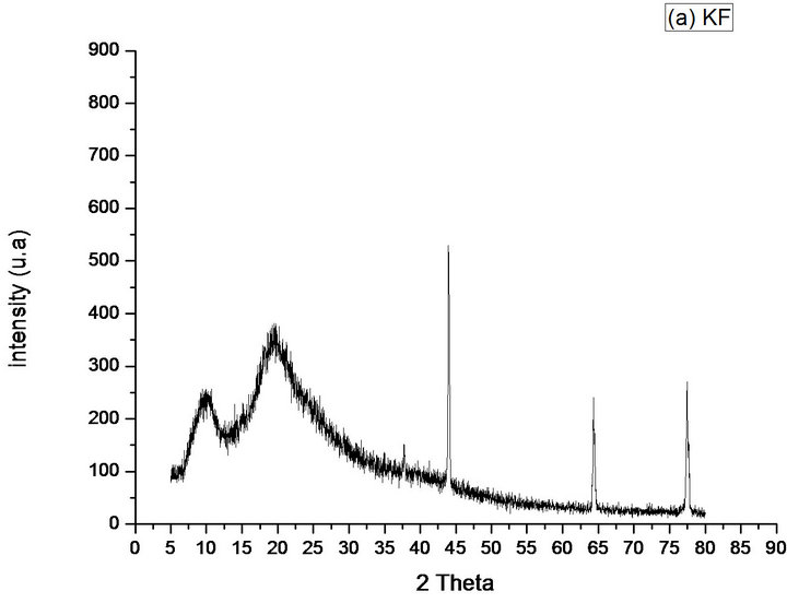
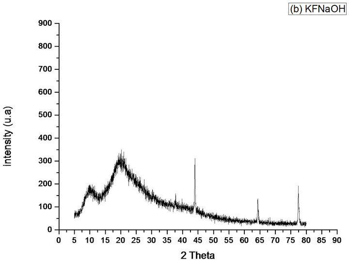
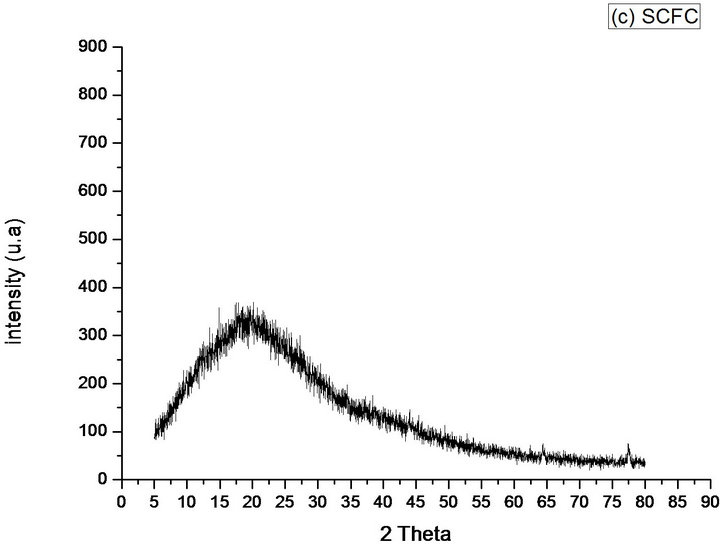
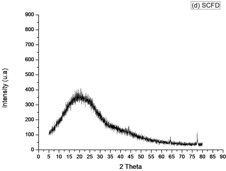
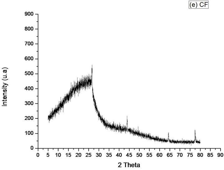
Figure 8. Diffractograms of the phases identified in Samples (a) KF; (b) KFNaOH; (c) SCFC; (d) SCFD; (e) CF.
preserves only 3 peaks of the KF (around 44˚, 64˚ and 77˚), with lower intensities in relation to the KF, in this region. As seen, the KF has diffraction standards more pronounced, in those positions, not only in relation to CF, but also observed in the other samples. The CF has more pronounced standard peak diffraction, compared to the one observed in SCFC and SCFD and produces an additional more intense peak around 26.7˚, in the position in which the other samples have an amorphous region, that is, the process of pyrolysis with an increase in temperature, produced further oriented crystals at this position (comparison with Figures 8(a)-(d). The material possesses an amorphous phase was evidenced by the presence of the reflection band in positions lower than 2θ = 26˚.
From the crystalline peaks, the crystallinity indexes were obtained using software (X’Pert High Score-Philips), and the Equation (1) was used to calculate the crystallite sizes. The data were used to compare and to evaluate the samples studied in this work. The CF presented the smallest crystallite size (27 nm), and the KFNaOH presented largest size (74 nm) (Table 1). Reference [18] confirms the results obtained in the present work regarding the presence of nanoparticles (<100 nm) between the micro particles in the samples.
The NaOH treatment decreased the crystallinity of the KF, and the CF was better preserved the semi crystalline structure of the same. Already the SCFC and SCFD obtained lower percentage of crystallinity when compared to other samples and although the SCFD has three peaks, the amorphous event is higher as compared with the SCFC, that has only two peaks (Table 1).
4. Conclusions
The study reports the physical structure and morphology of chicken feathers in natural and modified forms, benefiting the environment with its analysis for future uses. It took into account the intact structure and semi-crystalline structure of KF, to develop a carbonaceous material, more suitable for the manufacture of particulate composite materials (with the presence of micro-particles and nanoparticles), with better characteristics of durability and processing.
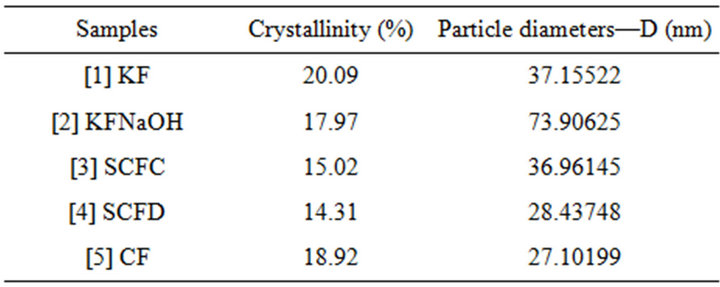
Table 1. Percentage crystallinity of the samples.
By comparative study, the CF presented structures with micro-pores and smaller size crystallites. It was also more efficient to preserve the semi-crystalline structure and the hollow micro-tubes of KF, but has lost knots and hooks, on the other hand, gained multilayer and closed micro-tubes and, consequently, increased the carbon-carbon links, which offer greater resistance to particulate composites. It was verified that the KFNaOH lost their hooks, have larger crystallites and lower crystallinity compared to KF and CF, but increased the surface porosity compared to KF. Due to oxidation of SCFC and SCFD, presented structures that are amorphous and brittle in their totality.
However, for the characterization of the materials studied, it is noted that the pyrolysis of waste obtained from chicken feathers in their natural form, is an efficient means for obtaining carbon with high specific area, for these conditions and this route of synthesis. The materials analyzed in this work are very promising because of their structures. In particular, the CF will enable future studies in the manufacture of carbon fibers of low-cost and in the search for its variant of smaller size (carbon nanotubes) in its structure, which has attracted much attention for improvements to thermal and mechanical property. Allied to these properties, which have expanded the science and technology of composite materials in recent decades and the environmental issue, in which millions of tons of chicken feathers are discarded as trash, annually, the proposed work offers economic and environmental benefits, and its marketing will contribute to be global sustainability.
5. Acknowledgements
The authors wish to express their gratitude to the projects CTPETRO-INFRA I and FINEPNEP/LIEM, NUPEG laboratory—UFRN, the Capes and the Post-graduate Program in Mechanical Engineering—UFRN.
REFERENCES
- N. Reddy and Y. Yang, “Structure and Properties of Chicken Feather Barbs as Natural Protein Fibers,” Journal of Polymers and the Environment, Vol. 1, No. 1, 2007, pp. 81-87. doi:10.1007/s10924-007-0054-7
- G. R. P. Moore, S. M. Martelli, C. A. Gandolfo, A. T. N. Pires and J. B. Laurindo, “Queratina de Penas de Frango: Extração, Caracterização e Obtenção de Filmes,” Ciência e Tecnologia de Alimentos, Vol. 26, No. 2, 2006, pp. 421- 427. doi:10.1590/S0101-20612006000200027
- M. K. Campbell, “Bioquímica,” 3th Edition, Artes Medicas Sul-Sul/Biomed, 2006.
- A. L. M. Hernandez and C. V. Santos, “Keratin Fibers from Chicken-Feathers: Structure and Advances in Polymer Composites,” In: R. Dullaart, et al., Eds., Keratin Structure, Properties and Applications, Nova Science Publishers, 2012, pp. 149-211.
- M. A. Meyers, P. Chen, A. Y. Lin and Y. Seki, “Biological Materials: Structure and Mechanical Properties,” Elsevier, Vol. 53, No. 1, 2008, pp. 1-206. doi:10.1016/j.pmatsci.2007.05.002
- H. B. Goyal, D. Seal and R. C. Saxena, “Bio-Fuels from Thermochemical Conversion of Renewable Resources: A Review,” Renewable and Sustainable Energy Reviews, Vol. 12, No. 2, 2008, pp. 504-517. doi:10.1016/j.rser.2006.07.014
- O. Sandru, “Carbonized Chicken Feathers Better Than Carbon Nanotubes at Storing Hydrogen,” The Green Optimistic, 2009. http://www.greenoptimistic.com/2009/06/25/carbonized-chicken-feathers-hydrogen-storage/
- A. V. Maciel, “Estudo dos Processos de Redução Carbotérmica de Compostos de Zn, Cd e Sn Assistidos pela Co-pirólise de Diferentes Biomassas Para a Obtenção de Materiais Nanoestruturados,” Ph.D. Thesis, Federal University of Minas Gerais, Belo Horizonte, 2010. http://www.bibliotecadigital.ufmg.br/dspace/bitstream/1843/SFSA-8CSNAF/1/tese_qu_mica_adriana_veloso_maciel.pdf
- E. Hammel, et al., “Carbon Nanofibers for Composite Applications,” Carbon, Vol. 42, No. 5-6, 2004, pp. 1153- 1158. doi:10.1016/j.carbon.2003.12.043
- P. Morgan, “Carbon Fibers and Their Composites,” Taylor & Francis, CRC Press, Boca Raton, 2005. doi:10.1201/9781420028744
- G. G. Tibbetts, M. L. Lakea, K. L. Strongb and B. P. Rice, “A Review of the Fabrication and Properties of VaporGrown Carbon Nanofiber/Polymer Composites,” Composites Science and Technology, Vol. 67 No. 7-8, 2007, pp. 1709-1718. doi:10.1016/j.compscitech.2006.06.015
- R. Piccoli, A. Mexias, R. Figueira, O. Montedo and F. Bertan, “Características das Principais Técnicas Analíticas Aplicadas à Caracterização de Materiais,” Brazilian Congress of Engineering and Materials Science, 17, Characterisation of Materials, Metallum, Foz do Iguaçu, Vol. 102, 2006, p. 28. http://www.metallum.com.br/17cbecimat/resumos/17cbecimat-102-028.pdf
- Belarmino, et al., “Estudo da Estabilidade Térmica de Fibra de Quertina—Keratin Fibre (KF) de Penas de Frangopara Obtenção de Carbono—CarbonisedFeatehrs (CF),” Holos Revista, Vol. 3, No. 3, 2012. http://www2.ifrn.edu.br/ojs/index.php/HOLOS/article/view/896
- D. C. F. Moreira, F. A. Sigoli and I. O. Mazali, “Avalia- ção da Influência da Cristalinidadesobre a Determinação do Tamanho de Cristalito do Óxidosemi-Condutor SnO2,” XIX Congress of Chemistry Institute, State University of Campinas, Campinas. http://www.prp.unicamp.br/pibic/congressos/xixcongresso/paineis/070632.pdf
- M. Munaro, “Stroke Development of Polyethylene Blends with Improved Performance for Use in Power Sector,” Ph.D. Thesis, Federal University of Paraná, Curitiba, 2007. http://www.pipe.ufpr.br/portal/defesas/tese/018.pdf
- I. F. Gimenez, O. P. Ferreira and O. L. Alves, “Desenvolvimento de Ecomateriais: Materiais Porosos Para Aplicação Em Green Chemistry (Química Verde),” State University of Campinas, Campinas. http://lqes.iqm.unicamp.br/images/publicacoes_teses_livros_resumo_nanoecomateriais.pdf
- A. M. F. M. Ventura, “Os Compósitos e a Sua Aplicação Na Reabilitação de Estruturas Metálicas,” Ciência & Tecnologia dos Materiais, Vol. 21, No. 3-4, 2009, pp. 10-19. http://www.scielo.gpeari.mctes.pt/scielo.php?pid=S0870-83122009000200003&script=sci_arttext
- R. K. Guptaamd, E. Kennel and K. Kim, “Polymer Nanocomposites Handbook,” Taylor & Francis, CRC Press, Boca Raton, 2009.