Circuits and Systems
Vol.07 No.09(2016), Article ID:68331,7 pages
10.4236/cs.2016.79190
Practical Implementation of Embedded Controlled Reduced Switch Z-Source Inverter-Fed Induction Motor Drive
K. Srinivasan1, T. Vijayakumar2
1Department of EEE, Tagore Engineering College, Chennai, India
2Sri Eshwar College of Engineering, Coimbatore, India

Copyright © 2016 by authors and Scientific Research Publishing Inc.
This work is licensed under the Creative Commons Attribution International License (CC BY).
http://creativecommons.org/licenses/by/4.0/


Received 18 Marc h 2016; accepted 15 April 2016; published 14 July 2016
ABSTRACT
A cost-effective component minimized embedded controlled Z-source inverter for induction motor drive is presented. The proposed topology combines the advantages of a traditional four-switch three-phase inverter with the advantages of the z impedance network (two inductors in series and two X connected capacitors). This new topology, besides the self-boost property, has low switch count and it can operate as a buck-boost inverter. As a result, the new embedded controlled reduced switch Z-source inverter system provides ride through capability during voltage sags, reduces line harmonics, improves power factor, reliability and extends output voltage range. Analysis, simulation and experiment result will be presented to demonstrate these new features.
Keywords:
Embedded Controller, Harmonic Distortion, Four-Switch Three-Phase Inverter, Z-Source Inverter

1. Introduction
Currently, there are two existing inverter topologies used for adjustable speed drives: The conventional three- phase Pulse Width Modulation (PWM) inverter and three-phase PWM inverter with a dc-dc boost converter [1] ; the conventional PWM inverter topology imposes high stresses to the switching devices and motor and limits the motor’s constant power speed ratio. The dc/dc boosted PWM inverter topology can alleviate the stresses and limitations [2] , however suffering from problems such as high cost and complexity associated with the two-stage power conversion. Z-source three-phase converters with six power switches have been proposed recently with different control strategies. Z-source inverter uses an impedance network (Z-network) to replace the traditional dc link. The newly proposed Z-source inverter [3] has the unique feature that it can boost the output voltage by introducing shoot through operation mode, which is forbidden in traditional voltage source inverters. With this unique feature, the Z-source inverter provides a cheaper, simpler, single-stage approach for applications of fuel cell. Moreover, it highly enhances the reliability of the inverter because the shoot through can no longer destroy the inverter. Traditionally, Six Switch Three Phase (SSTP) inverters have been widely utilized for variable speed induction motor (IM) drives [4] . These inverters have some drawbacks, which involve the losses of the six switches as well as the complexity of the control algorithms and interface circuits to generate six PWM logic signals. Some efforts have been made on the application of Four Switch Three Phase (FSTP) inverter for uninterruptible power supply and variable speed drives [5] . Advantages of the FSTP inverter over the conventional SSTP inverter are, reduced price due to reduction in number of switches, reduced switching losses, reduced number of interface circuits to supply logic signals for the switches, simpler control algorithms to generate logic signals, less chances of destroying the switches due to lesser interaction among switches and less real-time computational burden.
2. Modeling of Drive System
The complete drive system modeling involves the modeling of the inverter, induction motor and Z-source inverter, which are discussed in the following subsections.
2.1. Four-Switch Three-Phase Inverter Model
In the analysis, the inverter switches are considered as ideal power switches and it is assumed that the conduction state of the power switches is associated with binary variables S01 to S04 [4] . Therefore, a binary “1” will indicate a closed state, while “0” will indicate the open state. Pairs S01 to S03 and S02 to S04 are complementary and as a sequence:
 (1)
(1)
 (2)
(2)
Also, it will be assumed that a stiff voltage is available across the two dc-link capacitors and:
 (3)
(3)
where,  corresponds to a stiff dc-link voltage, i.e., the actual value of the dc-link voltage is equal to
 . The phase voltage equations of the motor can be written as a function of the switching logic of the switches and the dc-link voltage and given by [6] :
 (4)
(4)
 (5)
(5)
 (6)
(6)
where:
Va, Vb, Vc = Inverter output voltages;
Vdc = Be the voltage across the dc-link capacitors;
Sa, Sb = The switching functions for each phase leg.
In matrix form, the above equations can be written as:

For a balanced capacitor voltage, the four switching combinations lead to four voltage reactors as shown in Figure 1. Table 1 shows the different modes of operation and the corresponding output voltage vector of the inverter.
2.2. Z-Source Model
This Z-source inverter employs an impedance network connected between the inverter main circuit and to the main DC power source. This inverter has unique features compared with the conventional one. It consists of DC voltage source from the rectifier, Impedance network, reduced switch three phase inverter with squirrel cage induction motor load. AC voltage is rectified to dc voltage by the rectifier circuit, than rectified output dc voltage is fed to the Impedance network consisting of two equal inductors (L1, L2) and two equal capacitors (C1, C2). The network inductors are connected in series arms and capacitors are connected in diagonal arms as seen in Figure 2. The impedance network buck or boost the input voltage depending upon the buck boost factor [7] [8] . This impedance network also acts as a second order filter. This network required a minimum inductance and smaller in size. Similarly, capacitors required less capacitance and smaller in size.
3. Z-Source Inverter-Fed Induction Motor Drive
The Squirrel Cage Induction Motor Variable Frequency Drive (VFD) system suffers the following common restrictions. The rectifier voltage from the source can boost from 230 V to 310 V dc on the dc bus link, which is approximately 1.36 times the line to line input voltage under heavy load conditions. In a low power drives with no significant inductance, the line current becomes discontinuous and the dc voltage is closer to 1.41 times the

Figure 1. System configuration using reduced switch Z-source inverter.
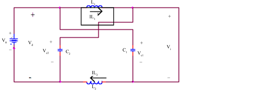
Figure 2. Equivalent circuit of the Z-source inverter.

Table 1. The four combinations of the states of the power switches and the corresponding terminal voltages Va, Vb and Vc are given in Table 1.
line to line input voltage, the low output voltage extensively limits output power that is proportional to the square of the voltage value [9] . The capacitor in VFD is a relatively small energy storage element, which cannot hold dc voltage above the operating level under such voltage sags. Solutions have been sought to boost ride- through [10] . The industrial drives provide options using fly back converter or boost converter with energy storage to achieve ride-through; however, these options come with penalties of cost, size and complexity. Inrush and harmonic current from the diode rectifier can pollute the line. Lagging of power factor is another major issue of the Squirrel cage induction motor VFD systems [6] . Performance and reliability are compromised by the voltage source VFD structure, because miss matching from EMI can cause shoot-through that leads to destruction of the VFD, the dead time that is needed to avoid shoot-through creates distortion and unstable operation at low speeds and common-mode voltage causes shaft current and premature failures of the motor. A proposed Z- source based VFD, has a niche for drives systems to overcome the aforementioned problems. The Z-source VFD system can produce an output voltage greater than the AC input voltage by controlling the boost factor [11] , which is impossible for the conventional squirrel cage induction motor drive systems. A Z-source VFD based Squirrel Cage Induction Motor drive can able to produce desired output voltage, irrespective of the input voltage, thus reducing motor ratings, endow with ride-through during voltage sags no need to connect any additional circuits to improve power factor, reduce harmonic current and common-mode voltage. In this study, the implementation of the reduced switch three phase Z-source VFD fed induction motor using PIC microcontroller PIC16F84A is presented.
4. Results and Discussion
In order to verify the effectiveness of the VFD configuration and its control strategy, a computer simulation model is developed using the MATLAB/SIMULINK software. Simulink model for Reduced switch Z-source inverter is shown in Figure 3. Squirrel Cage Induction motor current waveforms and voltage waveforms of the reduced switch three phase Z-source VFD are identical conditions with six switch three phase VFD [12] [13] . In Figure 4 shows line voltage waveform of reduced switch three phase Z-source inverter. It is evident that starting phase current is in the acceptable range. Three phase current in steady state condition shown in Figure 5 indicates balanced conditions of the reduced switch three phase Z-source VFD (Figure 6). Speed response and the harmonic spectrum of a phase current Ia, for the VFD is shown in Figure 7. The Total Harmonic Distortion (THD) of Ia is found 1.99% where as the THD of Ia for six switch three phase PWM VFD is found 8.70%.
The effectiveness of the Z-Source VFDs is proven by no overshoot, no undershoot and zero steady-state error

Figure 3. Simulink model for reduced switch Z-source inverter.
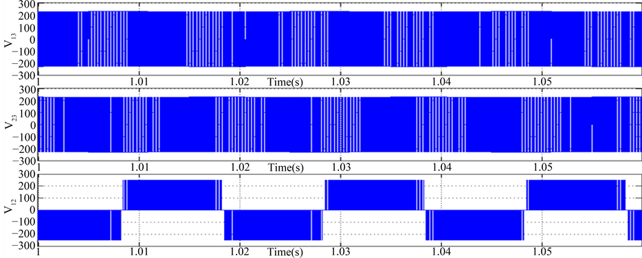
Figure 4. Line voltage waveform of reduced switch three phase Z-source inverter.

Figure 5. Three phase stator currents in the proposed method.

Figure 6. Speed response of reduced switch Z-source inverter.
of the speed response. It is also seen in Figure 6 and Figure 7 that the speed response and the harmonic distortion of the reduced switch three phase Z-source VFD based IM drive It is found that the performance of the reduced switch three phase Z-source VFD based drive is much close to that of the traditional six switches three phase VFD [14] . The analysis and simulation results show that this VFD can dramatically reduce the complexity of the control algorithms and cost.
5. Experimental Results
To experimentally validate the proposed embedded controlled reduced switch Z-source inverter for induction motor drive, a prototype has been built using MOSFETs as the switching devices and experimental tests load is a three phase induction motor (wound rotor, 0.5H.P), which is shown in Figure 8. In this paper the hardware is implemented using the IC microcontroller PIC16F84A. The advantages of the PIC microcontroller is that the instruction set of this controller are fewer than the usual microcontroller. Unlike conventional processors, which are generally complex instruction set computer (CISC) type. The advantages of RISC processor against CISC processor are RISC instructions are simpler and consequently operate faster, A RISC processor takes a single cycle for each instruction, while CISC processor requires multiple clocks per instruction (typically, at least three cycles of throughput execution time for the simplest instruction and 12 to 24 clock cycles for more complex instruction), which makes decoding a tough task, and the control unit in a CISC is always implemented by a micro-code, which is much slower than the hardware implemented in RISC. PIC16F84A microcontroller is used to generate triggering pulse for MOSFETs. It is used to control the output of the inverters. Micro controller have more advantage compare then analog circuits and micro processor such as fast response, low cost, small size and etc. Driver is also called as power amplifier because it is used to amplify the pulse output from microcontroller. It is also called as opto coupler IC. It provides isolation between microcontroller and power circuits.
The PIC16F84A belongs to the mid-range family of the PIC microcontroller devices. The program memory contains 1 K words, which translates to 1024 instructions, since each 14-bit program memory word is the same width as each device instruction. The data memory (RAM) contains 68 bytes. Data EEPROM is 64 bytes. Figure 9 shows the output voltage waveform of a reduced switch Z-source inverter.
6. Conclusion
This work has demonstrated that the reduced switch three-phase Z-source inverter topology is a good alternative technology to the conventional three-phase inverter for more efficient, more reliable and less cost conversion systems. The operating principle and analysis have been given by the current harmonics content simulation and experimental results verified the operation and demonstrated the promising features. In summary, the reduced switch three-phase Z-source inverter ASD system has several unique advantages that are very desirable for

Figure 7. Harmonic spectrum of reduced switch Z-source inverter.

Figure 8. Reduced switch Z-source inverter-fed induction motor drive prototype.

Figure 9. Output voltage waveform of reduced switch Z-source inverter.
many ASD applications. The experimental results closely agree with the simulation results. The reduced switch Z-source inverter employs a unique impedance network (or circuit) to couple the converter’s main circuit to the power source, thus providing unique features that cannot be observed in the conventional AC-AC converters. It can boost the input voltage, increase efficiency and reduce cost with minimized component count.
Cite this paper
K. Srinivasan,T. Vijayakumar, (2016) Practical Implementation of Embedded Controlled Reduced Switch Z-Source Inverter-Fed Induction Motor Drive. Circuits and Systems,07,2189-2195. doi: 10.4236/cs.2016.79190
References
- 1. Bose, U., Divya, K., Jyothi, V. and Sreejith, S. (2014) Performance Analysis of Four-Switch Three-Phase Inverter-Fed Induction Motor Drive. IEEE Power and Energy Systems Conference: Towards Sustainable Energy, Bangalore, 13-15 March 2014, 1-6.
http://dx.doi.org/10.1109/pestse.2014.6805315 - 2. Phutane, P.S. and Karpe, S.R. (2013) Performance of a 4-Switch, 3-phase Inverter Fed Induction Motor Drive System. International Journal of Advanced Research in Electrical, Electronics and Instrumentation Engineering, 2, 970-975.
- 3. Li, J., Liu, J.J. and Zeng, L. (2009) Comparison of Z-Source Inverter and Traditional Two-Stage Boost-Buck Inverter in Grid-Tied Renewable Energy Generation. IEEE 6th International Power Electronics and Motion Control Conference, Wuhan, 17-20 May 2009, 1493-1497.
- 4. Pandian, G. and Rama Reddy, S. (2008) Embedded Controlled Z Source Inverter Fed Induction Motor Drive. Journal of Applied Sciences Research, 4, 826-832.
- 5. Justus Rabi, B. and Arumugam, R. (2005) Harmonics Study and Comparison of Z-Source Inverter with Traditional Inverters. American Journal of Applied Sciences, 2, 1418-1426.
http://dx.doi.org/10.3844/ajassp.2005.1418.1426 - 6. Loh, P.C., Vilathgamuwa, D.M., Lai, Y.S., Chua, G.T. and Li, Y.W. (2005) Pulse-Width Modulation of Z-Source Inverters. IEEE Transaction on Power Electronics, 20, 1346-1355.
http://dx.doi.org/10.1109/TPEL.2005.857543 - 7. Shen, M., Wang, J., Joseph, A., Peng, F.Z., Tolbert, L.M. and Adams, D.J. (2004) Maximum Constant Boost Control of the Z-Source Inverter. Conference Record of the 2004 IEEE Industry Applications Conference, 3-7 October 2004.
- 8. Peng, F.Z., Shen, M.S. and Qian, Z.M. (2004) Maximum Boost Control of the Z-Source Inverter. IEEE Transactions on Power Electronics, 20, 833-838.
- 9. Elbadsi, B., Guermazi, A. and Masmoudi, A. (2005) New Space Vector PWM Strategy Intended for a Low-Cost Four- Switch Three-Phase Inverter-Fed Induction Motor Drive. Proceeding of the CD-ROM of the 3rd IEEE International Conference on Systems, Signals and Devices, Sousse, 21-24 March 2005.
- 10. Stockman, K., et al. (2004) Bag the Sags-Embedded Solutions to Protect Textile Process against Voltage Sags. IEEE Industry Applications Magazine, 10, 59-65.
http://dx.doi.org/10.1109/MIA.2004.1330771 - 11. Nasir Uddin, M., Radwan, T.S. and Rahman, M.A. (2004) Performance Analysis of Four Switch 3-Phase Inverter Fed IM Drives. 2004 Large Engineering Systems Conference on Power Engineering, 28-30 July 2004, 36-40.
http://dx.doi.org/10.1109/LESCPE.2004.1356262 - 12. Peng, F.Z. (2003) Z-Source Inverter. IEEE Transactions on Industry Applications, 39, 504-510.
http://dx.doi.org/10.1109/TIA.2003.808920 - 13. Cruise, R.J., Landy, C.F. and McCulloch, M.D. (1999) Evaluation of a Reduced Topology Phase-Converter Operating a Three-Phase Induction Motor. Proceeding of the IEEE International Electric Machines and Drives Conference, Seattle, May 1999, 466-468.
http://dx.doi.org/10.1109/iemdc.1999.769148 - 14. Van Zyl, A., Spee, R., Faveluke, A. and Bhowmik, S. (1998) Voltage Sag Ride through for Adjustable Speed Drives with Active Rectifiers. IEEE Transactions on Industry Applications, 34, 1270-1277.
http://dx.doi.org/10.1109/28.739005