Smart Grid and Renewable Energy
Vol.3 No.4(2012), Article ID:24606,4 pages DOI:10.4236/sgre.2012.34044
Rib and Groove Type Wind Guide Plate Analysis for Wind Power System
![]()
Department of Mechanical and Automation Engineering, Kao Yuan University, Kaohsiung, Chinese Taipei.
Email: csmoo@cc.kyu.edu.tw
Received July 23rd, 2012; revised August 23rd, 2012; accepted September 1st, 2012
Keywords: Rib; Groove; Wind Guide Plate
ABSTRACT
This research is the analysis of rib and groove type wind guide plate for wind generation power system. This device generates electricity by the air flow producing by the high-speed vehicles driving on the road. It can produce electricity as long as there are car passing on the high way. The effect is much more efficient in heavy traffic with high speed. If we can set up a large number of this system along the highway, it can provide the lighting in the highway at night but also sell the extra electricity to the power companies with low cost, high performances and improvement of environmental benefits.
1. Introduction
In the recent years, global warming, greenhouse and gas emissions are the major policy issues around the world, wind power is one of the cleanest types of power generation, the main advantage of energy resources is to reduce the power consumption of traditional fossil energy sources and reduce air pollution. In this study, we use Comsol Multi-physics software to simulate the wind guide plate with trough for wind power systems.
Windmills were used extensively in the Middle East by the eleventh century and in Europe by the thirteenth century. By the fourteenth century the Dutch used them for draining marshes and lakes. By the end of the nineteenth century, in Denmark there were about 2500 electricity-producing windmills with a generating capacity of about 30 MW, and about 4600 windmills being used for agricultural applications. Farmers and ranchers in the western United States began using small water-pumping windmills in the mid-nineteenth century. These wind machines were simple durable multi-bladed turbines with a high starting torque. An estimated 6.5 million machines were sold between 1880 and 1930, and in the 1930s the annual energy output was equivalent to 109 kWh per year. Beginning about 1925, small 0.2 - 3 kW horizontal-axis machines supplying dc electricity to operate appliances, usually at 32 V, were used in rural areas of the United States. The creation of the Rural Electrification Administration in 1936 soon brought electrical service to these rural areas and doomed the widespread use of the small machines.
Winds generally increase with height above the ground [1]. The jet streams, meandering currents of fast winds generally located between 7 and 16 km of altitude [2], have wind speeds that are an order of magnitude faster than those near the ground. Although the power in winds is not a function of wind direction, a variety of safety issues, such as interference with aviation operations, are associated with changes in wind direction. Furthermore, wind direction affects the operation and control of high-altitude devices [3].
In the past two decades, wind power has taken off as a producer of commercial electricity. Today it is the world’s most promising renewable energy technology and currently the world’s most rapidly growing energy source, whether conventional or renewable [4]. The wind industry is quite labor intensive and because of the rise of wind power, there has been a significant increase in jobs created. Generating power from the wind provides us with a clean form of electricity generation and creates zero CO2 emissions.
2. Basic Theory
Government Equation
Turbulent model and incompressible equation are as follows
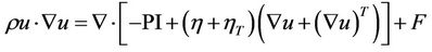 (1)
(1)
where  is turbulent viscosity,
  is dynamic viscosity, P is pressure, I is logarithm of turbulent dissipation rate.
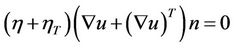
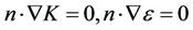
Boundary condition is considered pressure condition, non viscous stress condition:
 (2)
(2)
 (3)
(3)
 (4)
(4)
 (5)
(5)
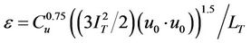
 is scale of turbulent,
  is velocity in x direction
  is constant;
 is scale length of turbulent;
When .
.
3. Analysis of Simulation
Figure 1 shows the experiment with wind guide plate. Table 1 shows the wind velocity without wind guide plate and wind guide plate. Table 1 can be found that the efficiency with wind guide plate. We can conclude that velocity distribution and efficiency are increased with wind guide plate.
Original Design
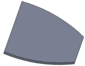
This research will design a set of guide trough wind plate used to support wind power as the object of study, the shape of rectangular-rib type, rectangular-grooved type, nozzle-rib type, and nozzle-grooved type using COMSOL Multi-physics software to analyze and explore the trench, and whether the rib and groove number of rib number so that the effect of the wind guide plate which is best for wind power generation. The shapes of rib and groove wind guide plate are shown as Figures 2-5.
4. Results and Discussions
The present results show that number of the shape of rectangular-rib type, rectangular-grooved type, nozzle-rib type, and nozzle-grooved type wind guide plate increase, the normal force will increase, therefore, the wind power will increase. In the other word, wind guide plate with groove (rib) is better than wind guide plate without groove (rib) shown in Figures 6-9.
5. Conclusion
This research shoes that wind guide plate accumulate air to the leaf blade of wind power system to generate electricity by the air flow producing by the high-speed vehi-

Figure 1. Experiment with wind guide plate.
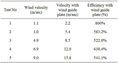
Table 1. Wind velocity with/without wind guide plate.
 (a)
(a) (b)
(b)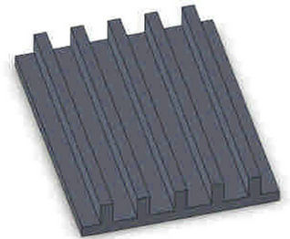 (c)
(c)
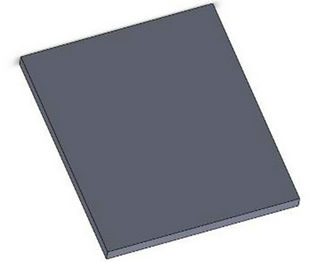
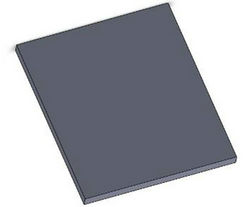
Figure 2. Rectangle-rib type of wind guide plate (length = 100 mm, width = 80 mm, thickness = 10 mm, rib height = 10 mm, rib thickness = 5 mm). (a) No rib; (b) 3 ribs; (c) 5 ribs.
 (a)
(a) (b)
(b)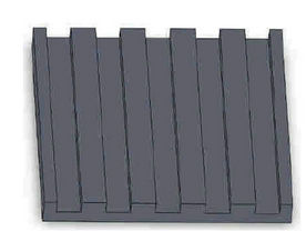 (c)
(c)
Figure 3. Rectangle-groove type of wind guide plate (length = 100 mm, width = 80 mm, thickness = 10 mm, groove width = 20 mm, groove depth = 5 mm). (a) No groove; (b) 3 grooves; (c) 5 grooves.
 (a)
(a)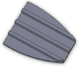 (b)
(b)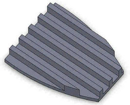 (c)
(c)
Figure 4 Nozzle-rib type of wind guide plate (length = 100 mm, width = 80 mm, thickness = 10 mm, rib height = 20 mm, rib thickness = 5 mm). (a) No rib; (b) 3 ribs; (c) 5 ribs.
 (a)
(a) (b)
(b) (c)
(c)
Figure 5. Nozzle-groove type of wind guide plate (length = 100 mm, width = 80 mm, thickness = 10 mm, groove width = 2 mm, groove depth = 5 mm). (a) No groove; (b) 3 grooves; (c) 5 grooves.

Figure 6. Wind force for different rectangle-groove number.
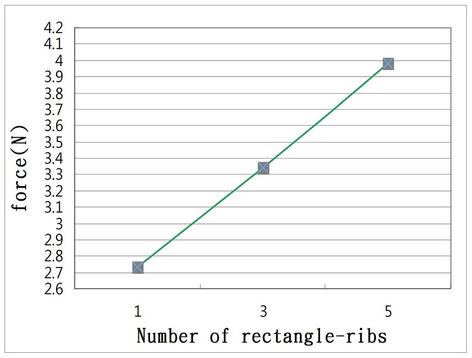
Figure 7. Wind force for different rectangle-rib number.

Figure 8. Wind force for different nozzle-groove number.
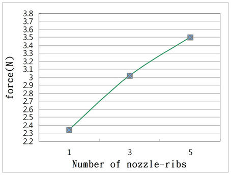
Figure 9. Wind force for different nozzle-rib number.
cles driving on the road. It can produce electricity as long as there are car passing on the high way. The number of the shape of rectangular-rib type, rectangular-grooved type, nozzle-rib type, and nozzle-grooved type wind guide plate increase, the normal force will increase, therefore, the wind power will increase. In the other word, wind guide plate with groove (rib) is better than wind guide plate without groove (rib). The effect is much more efficient in heavy traffic with high speed.
REFERENCES
- S. Arya, “Introduction to Micrometeorology,” Academic Press, New York, 1988, p. 303.
- P. Koch, H. Wernli and H. C. Davies, “An Event-Based Jet-Stream Climatology and Typology,” International Journal of Climatology, Vol. 26, No. 3, 2006, pp. 283- 301. doi:10.1002/joc.1255
- I. Argatov, P. Rautakorpi and R. Silvennoinen, “Estimation of the Mechanical Energy Output of the Kite Wind Generator,” Renewable Energy, Vol. 34, 2009, pp. 1525- 1532. doi:10.1016/j.renene.2008.11.001
- R. Y. Redlinger, P. D. Andersen and P. E. Morthorst, “Wind Energy in the 21st Century,” Palgrave Publishers Ltd., New York, 2002.