Energy and Power Engineering
Vol.5 No.3(2013), Article ID:31273,10 pages DOI:10.4236/epe.2013.53027
Inverter-Based Diesel Generator Emulator for the Study of Frequency Variations in a Laboratory-Scale Autonomous Power System
Department of Electrical and Computer Engineering, Concordia University, Montreal, Canada
Email: mi_torre@ece.concordia.ca, lalopes@ece.concordia.ca
Copyright © 2013 Miguel Torres, Luiz A. C. Lopes. This is an open access article distributed under the Creative Commons Attribution License, which permits unrestricted use, distribution, and reproduction in any medium, provided the original work is properly cited.
Received February 28, 2013; revised March 29, 2013; accepted April 11, 2013
Keywords: Diesel Generator; Emulator; Inverter; Frequency Control; Mini-Grid
ABSTRACT
This paper presents the modeling, simulation and practical implementation of an inverter-based diesel generator emulator. The main purpose of this emulator is for the study of frequency variations in diesel-based autonomous power systems in a laboratory environment where the operation of a real diesel generator is not possible. The emulator basically consists in a voltage source inverter with a second order output filter which voltage references are given by the model of the diesel generator. The control of the emulator is based on the digital signal processor TMS320F2812, where the mathematical models of the diesel generator and the control of the inverter are computed in real-time. Parameters for the model were obtained from commercially available components. Experimental results for different values of speed droop showed that the emulator achieves a satisfactory performance in the transient and stationary response. For the stationary response, the measured frequency deviates from theoretical values with a mean absolute error of: 0.06 Hz for 0% droop, 0.037 Hz for 3% droop, and 0.087 Hz for 5% droop. For the transient response, the measured frequency nadir deviates from simulations in: 0.05 Hz for 0% droop, 0.02 Hz for 3% droop, and 0.1 Hz for 5% droop.
1. Introduction
In conventional power systems electrical energy is primarily generated by means of rotating machinery and supplied in the form of ac voltage, where the frequency of the ac voltage is associated to the rotational speed of generators. Any imbalance between load and generation originates a change in the kinetic energy of rotating generators and therefore a change in frequency. In practice, frequency varies all the time due to a continuous interaction between loads and generators. The characteristics of such frequency variations will mainly depend, among other factors, on the type of disturbance affecting the power system, the performance of the frequency control system, and physical properties of generators. For instance, large interconnected power grids can be considered as stiff systems where a large power disturbance must occur before the frequency will deviate to any significant level. This is not necessarily the case for small power systems.
In general, frequency variations of consequence are more likely to occur in small power systems that are isolated from the utility grid since they feature a relatively small generation capacity, rapid changes in power demand, and low inertia [1]. Unwanted frequency variations might affect power system performance and even lead to system instability.
The work presented in this paper is part of a research project on dynamic control of frequency variations in diesel-based autonomous power systems (APS). The main objective of this paper is to present the modeling and implementation of a diesel generator emulator based on a voltage source inverter. An early version of the emulator as well as preliminary results was presented in [2]. The main motivations for developing the emulator are: the inverter-based emulator offers a more flexible solution for experimental setups than a machine-based emulator [3,4] and because our facilities are not suitable for the operation of a real diesel generator.
The rest of the paper is organized as follows: Section 2 presents a brief review of the frequency variation phenomenon and basic frequency control strategies used in APSs. Section 3 presents a general description of the emulator system, its main components and operation. Then, Section 4 presents the modeling of the diesel generator and Section 5 the control strategy for the inverter. In Section 6 relevant aspects of the digital implementation are discussed and experimental results are presented.
2. Frequency Control in APSs
2.1. The Frequency Variation Phenomenon
The diesel generator, also called generator set or genset, is one of the main components of the APS since it represents the primary source of energy and establishes the ac voltage in the system. A diesel generator basically consists of a rotating synchronous generator driven by a diesel engine [5]. Due to the physical principles involved in the process of energy conversion—from diesel fuel to electrical energy—the frequency of the output ac voltage is strongly coupled with the rotating speed of the diesel engine. Therefore, speed control of the diesel engine is crucial to frequency control.
Figure 1 depicts the block diagram of a basic speed control. In general terms, this control works as follows: a disturbance (e.g. a change in the electrical load) produces a change in the power balance of the genset, rotating speeds within the genset change accordingly, a change in the speed of the diesel engine is sensed by the governor, the control error is processed and then the corresponding control signal is sent to the fuel injection system, which produces the corresponding change in the fuel flow to the engine, finally the resulting interaction between the diesel engine and the synchronous generator produces a variation in the frequency of the output voltage.
For a single genset, frequency variations mainly depend on the following factors:
1) Characteristics of the electrical load and disturbance.
2) Physical characteristics of the electrical generator.
3) Physical characteristics of the coupling shaft.
4) Physical characteristics of the actuator and prime mover.
5) Type and performance of the speed controller.
Where the transient regime of a frequency variation is affected by the overall performance of the system, i.e., by a combination of all the factors previously mentioned. On the other hand, the steady-state frequency will be
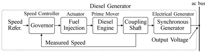
Figure 1. Main components of a typical diesel generator speed control.
mainly determined by the type of speed controller and its performance.
2.2. Frequency Control Strategies
In a small APS frequency control is usually achieved by primary control [6], which is performed by the speed governor of the diesel generator (Figure 1) by means of two strategies: isochronous control and permanent droop control [7].
Isochronous control refers to the ability of the prime mover to return to the original reference speed after a load change. This type of control is usually implemented by integrating the control error, and thus providing the necessary output to the actuator to return to its reference speed after a disturbance (Figure 2(b)). Therefore, an APS with a single generator in isochronous control will operate at fixed steady-state frequency as long as the generator is capable of supplying the power demanded by the load. Figure 2(a) shows the static relationship between power and frequency for a single generator in isochronous control mode.
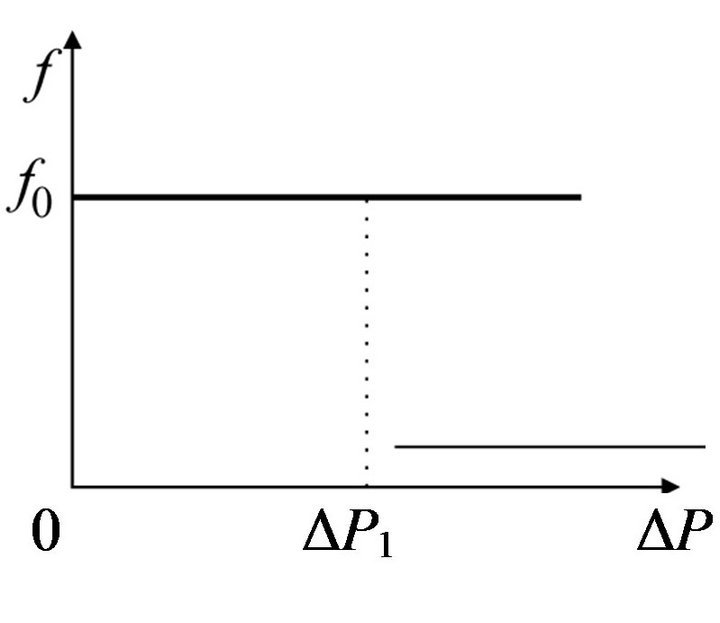
Permanent droop control refers to the ability of the prime mover to return to a different speed after a load change. This type of control is achieved by a proportional action over the actuator, based on the control error. When the load increases, the generator will stabilize to a speed lower than the original (Figure 2(d)). Conversely, when the load decreases, the generator will stabilize to a higher speed. Therefore, an APS with a single generator in permanent droop control will experience different operating frequencies as the load varies. Figure 2(c) shows the static relationship between power and frequency for a single generator in droop mode.
 (a)
(a)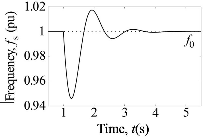 (b)
(b) (c)
(c)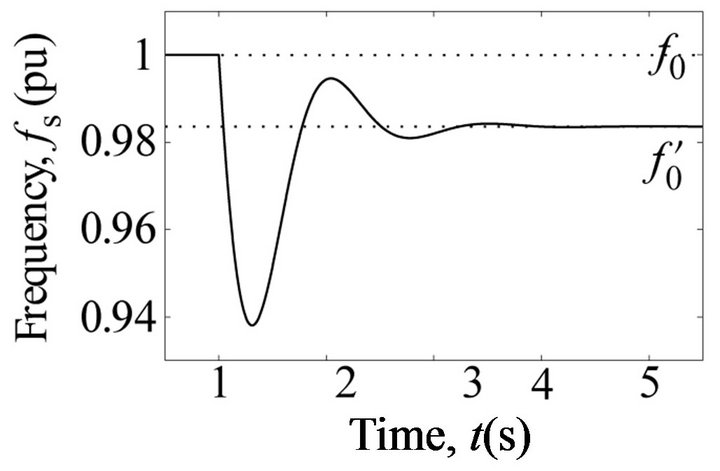 (d)
(d)
Figure 2. Frequency control strategies for prime movers in APSs. (a), (b) Isochronous control. (c), (d) Droop control.
3. Overview of the Emulator System
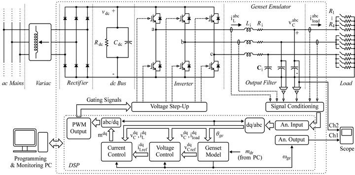
A general diagram of the emulator system is shown in Figure 3. The voltage source inverter (VSI) is a 2-level topology Semiteach-IGBT from Semikron. It has a 3-phase full wave diode rectifier to provide the dc power. The output filter is not included in the inverter, then additional inductors and capacitors should be connected on each phase. The load is a variable resistor bank. The digital control system is based on the Spectrum Digital development kit eZdsp-F2812 (DSP). All the programming is developed in C. A dedicated computer is needed for programming and monitoring. The voltage and current sensors designed for this project have the same structure: a Hall-effect transducer at the input, a gain and offset conditioning stage, and a buffer at the output. The signal conditioning stage is necessary to adapt the bipolar signals (measured ac currents and voltages) to the unipolar 3 V range of the DSP analog inputs. The PWM signals also have the same dynamic range, therefore it is necessary a voltage step up circuit to achieve the 15 V level of the inverter drivers.
In general terms, the emulator works as follows: the model of the diesel generator (genset) is programmed into the DSP and fed with the measured load currents, then the output voltages of the model are calculated and used as references to control the output voltages of the inverter. The controllers of the VSI, which also run in the DSP, produce the corresponding pulse width modulated (PWM) signals for the inverter. The analog outputs of the DSP are used to visualize in the scope internal variables of the genset model such as rotational speeds, torques, etc.
4. Modeling of the Diesel Generator
The block diagram of the diesel generator is shown in Figure 4. The model consists of five sub-models: the diesel engine, the synchronous generator, the coupling shaft, the automatic voltage regulator, and the speed governor, which are presented in the following sections.
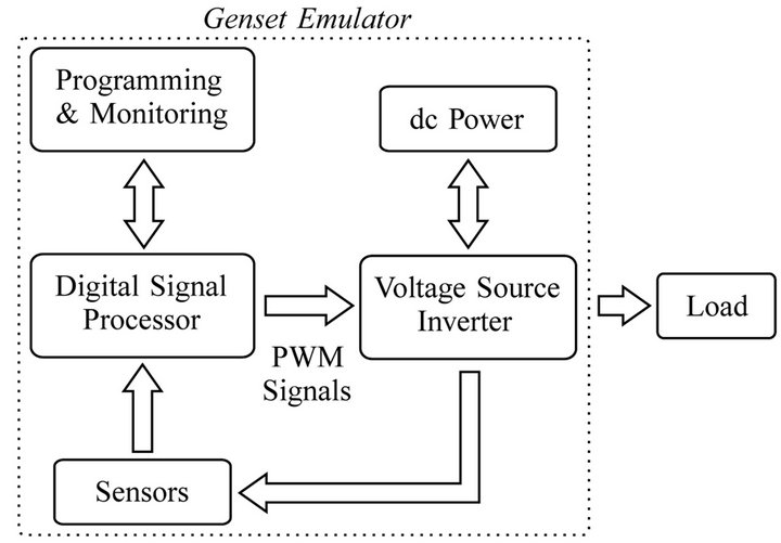
Figure 3. Block diagram of the emulator system.
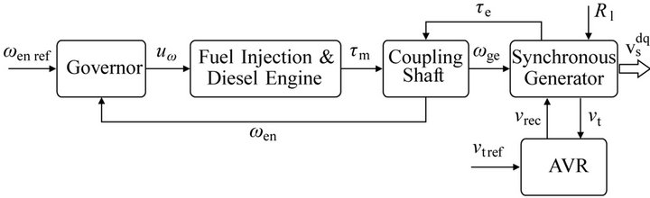
Figure 4. Diesel generator model.
4.1. Fuel Injection System and Diesel Engine
Several models for the diesel engine can be found in the literature [5,8-10] and the majority of them have in common three main elements: a fuel injection system represented as a first order model, a delay time representing the internal combustion delay, and the inertia of the internal rotating parts of the engine and flywheel. The effects of the inertia will be included in the model of the coupling shaft, therefore, the differential equation of the model (1) only includes the effects of the combustion delay and the dynamic of the fuel injection. The model equation is:
 (1)
(1)
where  is the control signal from the speed governor and
  is the mechanical torque developed by the engine. The parameters are
  the time constant of the fuel injection system,
  the gain of the engine, and
 ![]() is the delay that represents the elapsed time until torque is developed at the engine shaft. Since the control signal,
is the delay that represents the elapsed time until torque is developed at the engine shaft. Since the control signal,  , varies within the range
 , then the engine gain,
  , represents the maximum torque developed by the engine. The values of the parameters, summarized in Table 1, were obtained from the datasheet of a commercial diesel engine [11] and from an experimental setup used in [12].
4.2. Coupling Shaft
The coupling shaft of the genset is modeled as two rotational masses coupled by a flexible shaft. The equations of the model are:
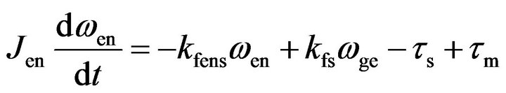 (2)
(2)
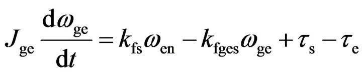 (3)
(3)
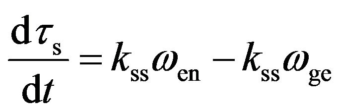 (4)
(4)
where the state variables are  the rotational speed of the prime mover,
  rotational speed of the electrical generator, and
  the torque transmitted through the shaft. The inputs are
  the mechanical torque supplied by the engine, and
  the electromagnetic torque due to
Table 1. Diesel engine parameters.
electric load. The parameters are 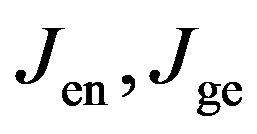 and
and ,
,  the moments of inertia and the frictional losses coefficients of the engine and electrical generator,
  and
and  the damping and torsional stiffness coefficients of the shaft, with
  and
and . Parameters of model (2) were obtained from datasheets [11,13,14] and they are summarized in Tables 1-3.
4.3. Electrical Generator
The electrical generator is represented by model 2.1 of the “IEEE standard for synchronous generator modeling” [15]. This model consists of two windings—field and damper windings—in the d-axis of the rotor, and a single damper winding in the q-axis. Inductances for this model were derived from reactances given in the datasheet of the synchronous generator [13]. Main parameters are summarized in Table 3.
4.4. Genset Control
4.4.1. Automatic Voltage Regulator
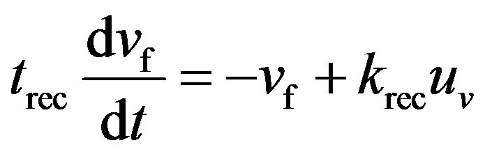
The proposed model for the AVR is based on information provided by the IEEE Std. 421.5 [16)] and the datasheet of the synchronous generator [13]. The model consists of a single-phase thyristor rectifier—modeled as a first order system [17]—controlled by a proportionalintegral (PI) controller (Figure 5(a)). The PI controller is provided with anti-windup function which, i.e., the integrative function is disabled  when the output
  goes beyond the limits
 . The equations of the model are:
 (5)
(5)
 (6)
(6)
 (7)
(7)
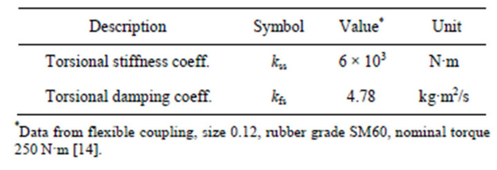
Table 2. Parameters of mechanical shaft.
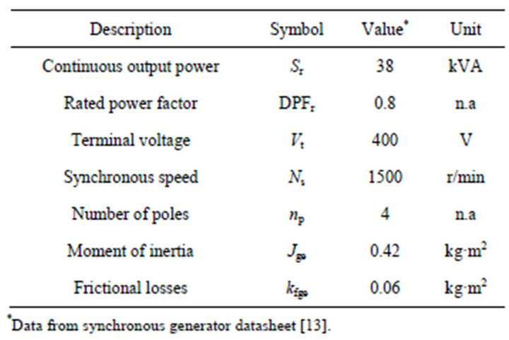
Table 3. Parameters of the synchronous generator.
 (a)
(a)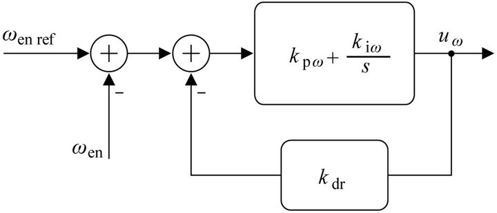 (b)
(b)
Figure 5. Genset control block diagrams. (a) Automatic voltage regulator; (b) Prime mover speed governor.
where the variables are ![]() the measured terminal voltage,
the measured terminal voltage,  the terminal voltage reference,
  the integrator state,
  the output of the controller, and
  the output voltage of the AVR rectifier which is the input for the rotor external winding. The parameters are
  the proportional control gain,
  the integral control gain,
  and
and  the time constant and gain of the AVR rectifier.
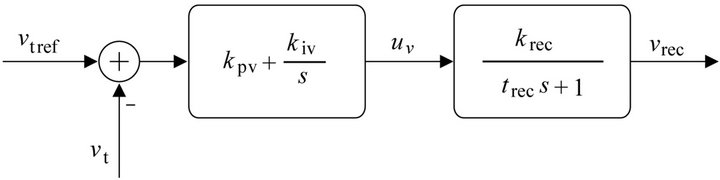
4.4.2. Speed Governor
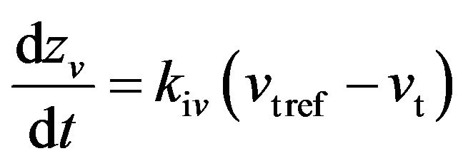
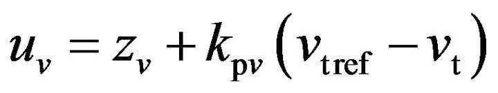
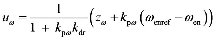
The speed governor [18] has the structure of a PI controller and the droop function is implemented with the feedback of the controller output (Figure 5(b)). The output of the controller is limited to the range  in order to represent the operating stroke of the actuator [19]. As described before for the AVR, the speed governor is also provided with an anti-windup integrator. The equations of the model are:
 (8)
(8)
 (9)
(9)
where the variables are:  the speed reference,
  the integrator state, and
  the output of the controller. The parameters are
  the proportional control gain,
  the integral control gain, and
  the speed droop gain. The speed droop gain is defined as
 , where
  is the static droop slope, and
  is the nominal speed of the prime mover in (rad/s).
4.5. Simulation
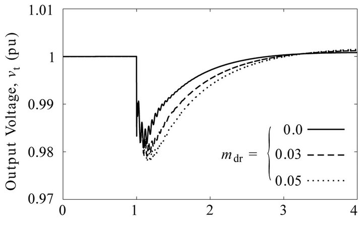
The AVR and speed governor are tuned in order to comply with performance class G3 of the standard ISO 8528:5 [20]. Controller parameters are summarized in Tables 4 and 5. Simulations were conducted to verify the transient performance for maximum loading and unloading conditions. Figure 6 shows the the results for different values of droop and Table 6 compares the results with the specifications of the standard.
5. Control of the Voltage Source Inverter
The model for this inverter (Figure 7) is well documented in the literature, therefore we refer the reader to [21] for more details on the modeling. The equations for the inverter are the following:
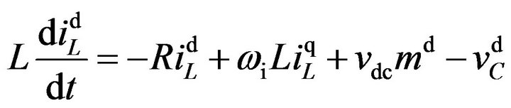 (10)
(10)
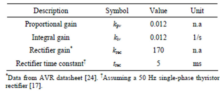
Table 4. Parameters of genset AVR.
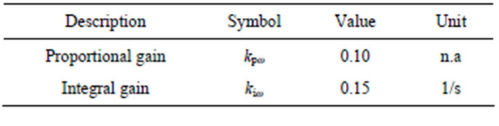
Table 5. Parameters of genset speed governor.
Time, t(s)
(a)

Time, t(s)
(b)
Figure 6. Genset model transient response for different values of droop. Waveforms for a 50% load increase at t = 1 s and three different values of speed droop. (a) Rms value of the output terminal voltage; (b) Prime mover rotational speed.

Table 6. Comparison between simulation results and class G3 ISO 8528:5 specifications.
.
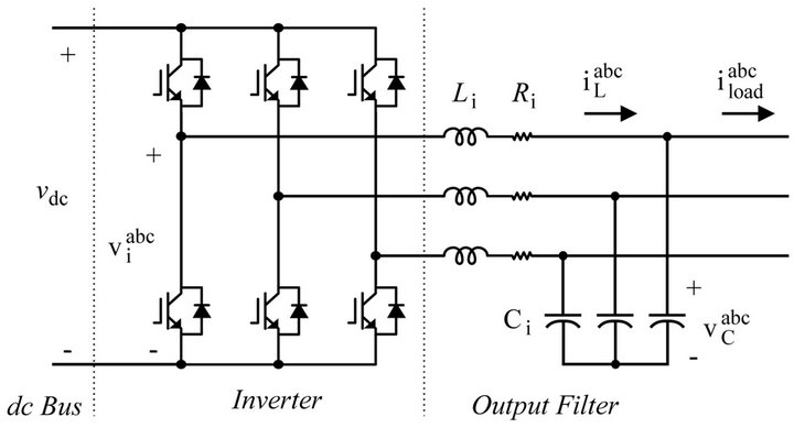
Figure 7. Voltage source inverter topology.
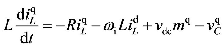 (11)
(11)
 (12)
(12)
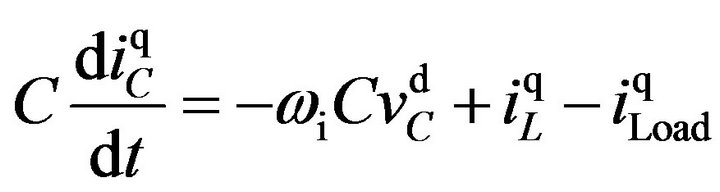 (13)
(13)
where![]() ,
, ![]() and
and ,
,  are the inverter output currents and voltages,
  and
and  are the load currents,
  is the dc bus voltage,
  and
and  the modulation indexes, and
  is the output frequency of the inverter. Note that by defining
  the output frequency is the generator speed from the genset model. As mentioned in Section 3 the references calculated with the genset model are the genset output voltages
  and
and , therefore a voltage control strategy is proposed for the VSC. In order to follow the references with a desired dynamic performance, voltage control requires inner control loops for the output currents
![]() ,
,![]() . The control strategy is designed in two steps, first the inner current control loops and then the outer voltage loops.
. The control strategy is designed in two steps, first the inner current control loops and then the outer voltage loops.
5.1. Current Control
The proposed control law—based on input-output linearization [22]—consists in defining the modulation index as:
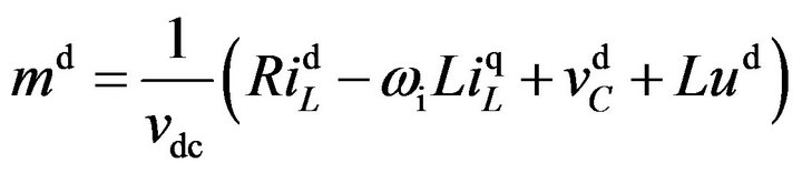 (14)
(14)
where  is the new input. By replacing (14) in (10) the new equation
 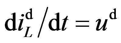 is obtained. Now,
  must be defined in such a way that the desired dynamics between the current
 ![]() and its refe
and its refe ![]() rence
rence  are achieved in closed-loop. Therefore, by defining the new input in the
 ![]() -domain as:
-domain as:
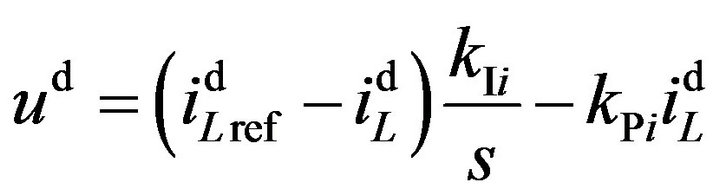 (15)
(15)
the following second order transfer function is obtained:
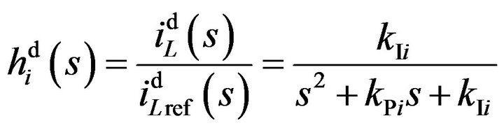 (16)
(16)
where  and
and  are the parameters of the control Equation (15). Since (16) has the form of a standard second order transfer function, its parameters can be defined as
  and
and , where
  is the natural frequency and
  the damping ratio. The same control method is used for the q axis current and both controllers are tuned with the same parameters (see Table 7).
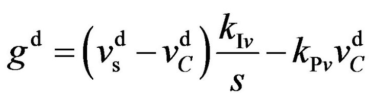
5.2. Voltage Control
Assuming that the current dynamics have been set suffi-

Table 7. Parameters of the setup control system.
ciently faster than the desired voltage dynamics, then the output currents might be considered equal to its references and therefore they can be used as the control inputs in (12) and (13). The same control technique used for the output currents can be applied to the output voltages by defining the current reference as:
 (17)
(17)
where  is the new input. By replacing (17) in (12) the new equation
  is obtained. Now,
  must be defined in such a way that the desired dynamics between the voltage
  and its reference
 —the output voltage of the genset model—are achieved in closedloop. Therefore, by defining the new input in the s-domain as:
 (18)
(18)
the following second order transfer function is obtained:
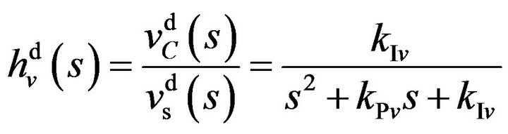 (19)
(19)
where  and
and  are the parameters of the control Equation (18). Similarly, as in the case of the output currents, controller parameters can be defined as
  and
and , where
  is the natural frequency and
  the damping ratio. The same control method is used for the q axis voltage and both controllers are tuned with the samsse parameters (see Table 7).
6. Experimental Tests
Figure 8 shows pictures and the setup. Parameters of the power circuit are summarized in Table 8. Two tests were performed on the emulator: one to verify its static
 (a)
(a)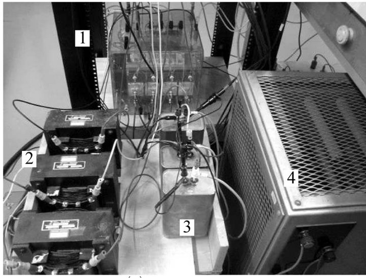 (b)
(b)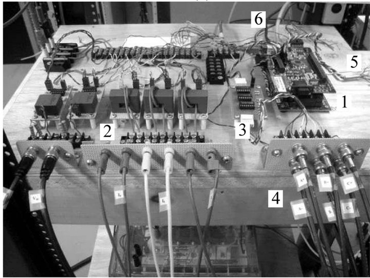 (c)
(c)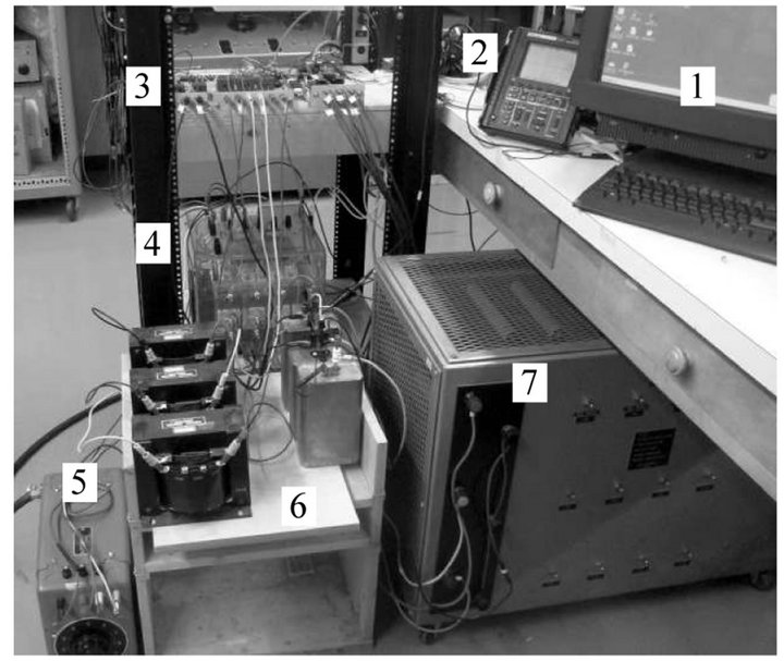 (d)
(d)
Figure 8. Experimental setup of the genset emulator. (a) Schematic; (b) Overview, 1: programming and monitoring PC, 2: scope, 3: control system, 4: inverter, 5: variac, 6: output filter, 7: load; (c) Control system, 1: DSP board, 2: voltage and current sensors, 3: PWM step up, 4: gating signals, 5: analog outputs, 6: PC communication; (d) Power circuit, 1: inverter, 2: filter inductors, 3: filter capacitors, 4: load resistors.

Table 8. Parameters of the setup power circuit.
frequency droop curve (steady state response), and a second one to verify its transient response. Both tests were performed for three different values of speed/frequency droop:  (isochronous control),
  and
and . In all cases the emulator operated at a nominal phase voltage of
  rms. Channel 1 of the scope measured the generator speed
  (through an analog output of the DSP) and channel 2 measured the output voltage of the emulator on phase a,
 .
.
6.1. Steady-State Response
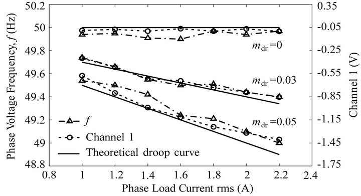
This test consisted in varying the load of the emulator to obtain the steady-state response for different values of droop factor and load level. The obtained data was compared with theoretical droop curves. Figure 9 shows the results of this test.
Figure 9(b) shows the emulator speed when it operates with 0% droop (isochronous control). It can be observed that, for different load levels, there is practically no variation of speed  in steady state. In the same way, Figure 9(c) shows the emulator speed for different load levels when it operates with 3% droop, where it can be observed that the generator speed
  decreases in steady state as the load increases. Finally, the same test of load variation is repeated with the emulator operating at 5% droop. Figure 9(d) shows the results, where it can be seen that the generator speed
  decreases in steady state as the load increases and, as expected, the steady state variations are greater than in the case of 3% droop.
(a)
(b)

(c)

Time (s)
(d)
Figure 9. Emulator steady-state response for different values of droop factor and load levels. (a) Experimental and theoretical static droop curves; (b) 0% droop; (c) 3% droop; (d) 5% droop.
Figure 9(a) summarizes in one graph the results of the above three tests, where for each value of droop the following three curves are plotted: the theoretical droop curve, the droop curve of the generator speed , and the droop curve of the frequency of
 . In the case of the speed droop curve the data is directly obtained from the measured voltage on channel 1 (Figures 9(b)- (d)), whereas in the case of the frequency droop curve the data correspond to the instantaneous values displayed on the scope.
6.2. Transient Response
This test consisted in a sudden load increase to obtain the transient response of the emulator and compare it with simulation results. The emulator started in steady-state with a nominal load of  per phase. Then, load
  was connected at the same time in each phase, resulting in an equivalent nominal load per phase of
 .
.
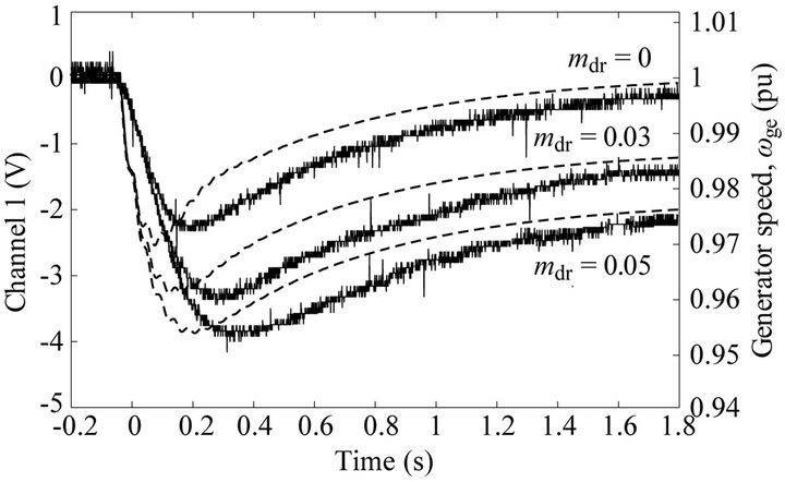
Figure 10(a) shows the speed transient response of the emulator for the three values of droop. Figure 10(b) shows a detailed view of the moment when the speed nadir (Ch1) occurs for the case of 0% droop. Channel 2 shows the actual phase voltage whose frequency is 48.6 Hz. According to simulations, the expected frequency for this case is 48.55 Hz (0.971 pu). In the same way, Figure 10(c) shows the speed nadir (Ch1) for the case of 3% droop. Channel 2 shows the actual phase voltage whose frequency is 48.12 Hz. According to simulations, the expected frequency for this case is 48.1 Hz (0.962 pu). Finally, Figure 10(d) shows the speed nadir (Ch1) for the case of 5% droop. Channel 2 shows the actual phase voltage whose frequency is 47.85 Hz. According to simulations, the expected frequency for this case is 47.75 Hz (0.955 pu).
6.3. Comments on the Digital Implementation
The nonlinear continuous-time model of the genset (Section (4)) was linearized and discretized considering a sampling time equal to 100 μs, which is the period of the control timer of the DSP. Therefore, the model of the genset was programmed in the following state-space form:
 (20)
(20)
 (21)
(21)
where

is the state vector,  the input,
  the
the
 (a)
(a)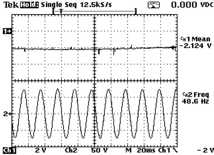 (b)
(b)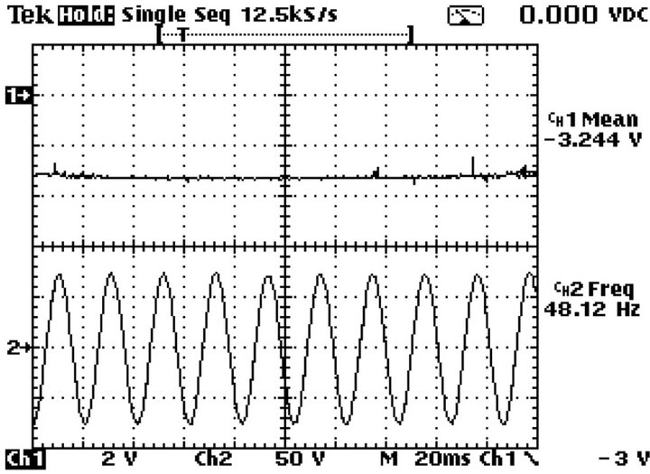 (c)
(c)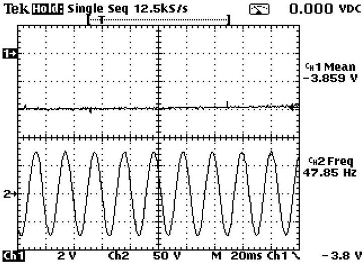 (d)
(d)
Figure 10. Emulator transient response for different values of droop factor. (a) Speed waveforms. (b), (c) and (d) Speed nadir (Ch1) and phase voltage (Ch2) for 0%, 3% and 5% droop, respectively.
output, and  the matrices and vectors of the linearized system.
The effect of the combustion delay time was neglected in (20) for two reasons: its value is very small compared to the rest of the system dynamics, and its state-space representation requires at least two state variables (which have to be added to system (20), increasing its size and complexity) in order to have a good approximation of the delay.
The input to the genset model,  , was calculated from the actual load of the setup,
 . The latter was estimated from the measured voltage and current as follows:
 (22)
(22)
where  is the estimated value of the actual load of the setup.
7. Conclusion
This work presented the modeling, simulation, and the practical implementation of an inverter-based diesel generator emulator. The main purpose of this emulator is for the study of frequency variations in diesel-based autonomous power systems in a laboratory environment where the operation of a real genset is not possible. Experimental results for different values of speed droop showed that the emulator achieved a satisfactory performance in the transient and stationary response. For the stationary response, the measured frequency deviated from theoretical values with a mean absolute error of: 0.06 Hz for 0% droop, 0.037 Hz for 3% droop, and 0.087 Hz for 5% droop. As for the transient response, the measured frequency nadir deviated from simulations in: 0.05 Hz for 0% droop, 0.02 Hz for 3% droop, and 0.1 Hz for 5% droop. Further experimentation is required in order to evaluate the performance of the emulator in parallel operation with active components, because future work will consider the use of the emulator in a laboratory-scale mini-grid system.
REFERENCES
- IEEE Std. 1159-2009 (Revision of IEEE Std. 1159-1995) Recommended Practice for Monitoring Electric Power Quality, IEEE Std., 2009.
- M. Torres and L. A. C. Lopes, “Inverter-Based Virtual Diesel Generator for Laboratory-Scale Applications,” IECON 2010—36th Annual Conference on IEEE Industrial Electronics Society, Glendale, 7-10 November 2010, pp. 532-537.
- M. Armstrong, D. Atkinson, A. Jack and S. Turner, “Power System Emulation Using a Real Time, 145 kw, Virtual Power System,” 2005 European Conference on Power Electronics and Applications, Dresden, 10-15 September 2005, 10 Pages.
- M. Oettmeier, R. Bartelt, C. Heising, V. Staudt, A. Steimel, S. Tietmeyer, B. Bock and C. Doerlemann, “Machine Emulator: Power-Electronics Based Test Equipment for Testing High-Power Drive Converters,” 2010 12th International Conference on Optimization of Electrical and Electronic Equipment (OPTIM), Basov, 20-22 May 2010, pp. 582-588.
- I. Boldea, “Synchronous Generators Handbook,” In: L. L. Grigsby, Ed., 1 em Plus 0.5 em Minus 0.4 em, CRC Press, Boca Raton, 2006, 448 Pages.
- Y. Z. Sun, Z. S. Zhang, G. J. Li and J. Lin, “Review on Frequency Control of Power Systems with Wind Power Penetration,” 2010 International Conference on Power System Technology (POWERCON), Hangzhou, 24-28 October 2010, pp. 1-8.
- R. Cosse, M. Alford, M. Hajiaghajani and E. Hamilton, “Turbine/Generator Governor Droop/Isochronous Fundamentals—A Graphical Approach,” Petroleum and Chemical Industry Conference (PCIC), 2011 Record of Conference Papers Industry Applications Society 58th Annual IEEE, Toronto, 19-21 September 2011, pp. 1-8.
- A. J. Wood and B. F. Wollenberg, “Power Generation, Operation and Control,” John Wiley and Sons, Inc., Hoboken, 1996, 592 Pages.
- S. Roy, O. Malik and G. Hope, “A Low Order Computer Model for Adaptive Speed Control of Diesel Driven PowerPlants,” Industry Applications Society Annual Meeting, 1991, Conference Record of the 1991 IEEE, Dearborn, 28 September-4 October 1991, pp. 1636-1642.
- S. Roy, “A Least-Squares Based Model-Fitting Identification Technique for Diesel Prime-Movers with Unknown Dead-Time,” IEEE Transactions on Energy Conversion, Vol. 6, No. 2, 1991, pp. 251-256. doi:10.1109/60.79629
- Technical Specification: The Genset Engine 912 Series, Deutz AG, dic 1998. http://j.mp/F4L912GEN
- H. Nikkhajoei and R. Lasseter, “Distributed generation interface to the CERTS microgrid,” IEEE Transactions on Power Delivery, Vol. 24, No. 3, 2009, pp. 1598-1608. doi:10.1109/TPWRD.2009.2021040
- Technical Specification: Synchornous Generator for Diesel/ Gas Engine Industrial Application Series, 8AMG5862124, ABB Generators Ltd., 2011. http://j.mp/AMG0200AA04
- RB and PM Hi-Tec Industrial Couplings, Renold plc, abr 2010. http://j.mp/RenoldCoupling
- IEEE Std. 1110-2002 Guide for Synchronous Generator Modeling Practices and Applications in Power System Stability Analyses, IEEE Std., 2003.
- IEEE Std. 421.5-2005 (Revision of IEEE Std. 421.5-1992) Recommended Practice for Excitation System Models for Power System Stability Studies, IEEE Std., 2006.
- R. Krishnan, “Electric Motor Drives: Modeling, Analysis, and Control,” Prentice-Hall, Upper Saddle River, 2001, 626 Pages.
- SDG500 Series Smart Digital Governor, Governors America Corp., 2010. http://j.mp/GovSDG500
- 176 Series Integral Electrical Actuator, Governors America Corp., 2005. http://j.mp/GAC176actuator
- ISO 8528-5:2005 Reciprocating Internal Combustion Engine Driven Alternating Current Generating Sets—Part 5: Generating Sets, ISO Std., 2009.
- M. H. Rashid, “Power Electronics Handbook,” Academic Press, San Diego, 2007, 895 Pages.
- T. S. Lee, “Input-Output Linearization and Zero-Dynamics Control of Three-Phase ac/dc Voltage-Source Converters,” IEEE Transactions on Power Electronics, Vol. 18, No. 1, 2003, pp. 11-22. doi:10.1109/TPEL.2002.807145
- S. Krishnamurthy, T. Jahns and R. Lasseter, “The Operation of Diesel Gensets in a CERTS Microgrid,” Power and Energy Society General Meeting—Conversion and Delivery of Electrical Energy in the 21st Century, 2008 IEEE, Pittsburgh, 20-24 July 2008, pp. 1-8.
- Automatic Voltage Regulator EA63-5 User Manual, 8AMG- 5855292, ABB Generators Ltd., Ago 2010. http://j.mp/AVR_EA635