Energy and Power Engineering
Vol. 4 No. 4 (2012) , Article ID: 20211 , 7 pages DOI:10.4236/epe.2012.44034
Sensorless Vector Control of Induction Generators for Variable-Speed Wind Turbines Using Micro-2407
1Synergy Institute of Technology, Biju Pattnaik University of Technology, Bhubaneswar, India
2Orissa Engineering College, Biju Pattnaik University of Technology, Bhubaneswar, India
Email: rabiparida@rediffmail.com, bibhunanda1986@yahoo.com, jeevan_mishra2000@yahoo.co.in
Received October 12, 2011; revised November 25, 2011; accepted December 4, 2011
Keywords: Fuzzy Logic; Induction Generator; Induction Motor Drives; Spectral Analysis; Wind Energy
ABSTRACT
A sensorless vector-control strategy for an induction generator in a grid-connected wind energy conversion system is presented. The sensorless control system is based on a model reference adaptive system (MRAS) to estimate the rotational speed. In order to tune the MRAS observer and compensate for the parameter variation and uncertainties, a separate estimation of the speed is obtained from the rotor slot harmonics using an algorithm for spectral analysis. This algorithm can track fast dynamic changes in the rotational speed, with high accuracy. Two back to back pulse width modulated (PWM) inverters are used to interface the induction generator with the grid. The front-end converter is also vector controlled. The dc link voltage is regulated using a PI fuzzy controller. The proposed sensorless control strategy has been experimentally verified on a 2.5-kW experimentally set up with an induction generator driven by a wind turbine emulator. The emulation of the wind turbine is performed using a novel strategy that allows the emulation of highorder wind turbine models, preserving all of the dynamic characteristics. The experimental results show the high level of performance obtained with the proposed sensorless vector-control method.
1. Introduction
The advantages of cage induction machines are well known. These machines are relatively inexpensive, robust, and require low maintenance. When induction machines are operated using vector-control techniques, fast dynamic response and accurate torque control are obtained [1]. All of these characteristics are advantageous in variable-speed wind energy conversion systems (WECS). The control systems for the operation of indirect rotorflux-oriented (IRFO) vector-controlled induction machines for variable-speed wind energy applications have already been discussed in [1-3], cage induction machines are considered and a fuzzy control system is used to drive the WECS to the point of maximum energy capture for a given wind velocity. The induction machine is connected to the utility using back to-back converters. In [1-3], speed encoders are used to implement the vector control strategies. The use of this encoder implies additional wiring, extra cost, extra space, and careful mounting which detracts from the inherent robustness of cage induction machines [4-6].
In this paper, a sensor less control structure based on a direct rotor flux-oriented (DRFO) vector-control system, for variable speed wind energy applications, is discussed. A speed estimation, obtained from a model reference adaptive system (MRAS) [4], is used to control the electrical torque of the induction machine. A V/F control strategy is used in the low-speed region for starting and driving the WECS set into the speed operating range. In order to tune the MRAS system and compensate for the variation of the machine parameters, an estimation of the rotational speed is obtained from the rotor slot harmonics (RSH) [7,8]. The spectral analysis method used in this publication can track the rotational speed not only in steady state but also when the WECS is subjected to fast dynamic changes.
The system proposed in this paper is shown in Figure 1. An induction generator is driven from an emulated variable-speed wind turbine. An IPM, Micro-2407 based system is used to implement the DRFO algorithms, the V/F control strategy, the MRAS rotational speed observer, the spectral estimation algorithm, the control of the front-end converter, and the emulation of the wind turbine. The front-end converter supplies the electrical energy into the grid. This converter controls the dc link voltage of the back-to-back configuration using a fuzzy PI controller. The dq currents and voltages of the induction machine are referred to a reference frame aligned to the rotor flux. These currents take dc values in steady
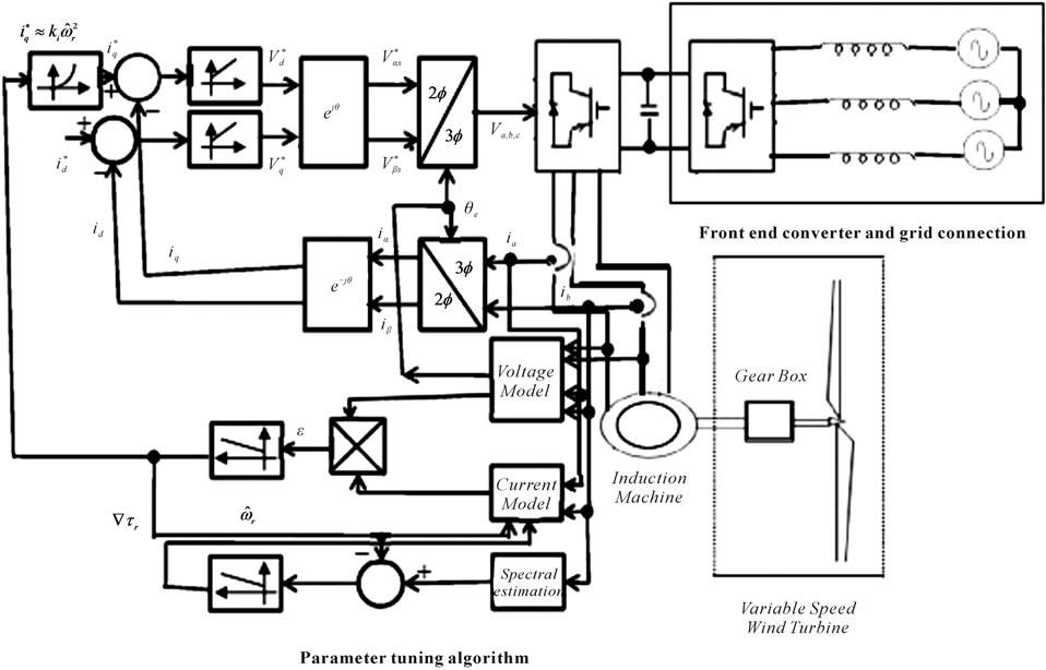
Figure 1. Control system proposed.
state. The rotor flux is calculated from the machine voltages and currents (“Voltage Model” in Figure 1). The α-β components of the flux are used to calculate the electrical angle θe for the vector rotators [9-22].
The output is Δτr which is added to drive the estimation of the rotor time constant to the correct value. The tuning algorithm is switched off for fast speed changes to avoid the relatively large speed errors produced at the output of the RML-ATF filter (in practice, this does not take place very often because of the large inertia of WECS). Due to the reduced slip at light load, small errors in the estimated speed may produce a large variation in the estimated rotor time constant. To avoid this, the tuning algorithm is also switched off when the  current is small.
2. Experimental Results
A 2.5-kW, 380-V, 50-Hz, four pole cage induction machine is utilized in the experimental prototype. The machine parameters are given in the Appendix. Two 5-kW commercial inverters with a 1-kHz switching frequency are used. The supply-side converter is connected to the grid via three 12-mH single-phase inductors. The dc link voltage is regulated to 550 V. A speed encoder of 10,000 ppr is used to calculate the system speed. This speed is not used in the control algorithms and it is only used for comparison purposes and the emulation of the wind turbine. In the machine side, two line currents and two line voltages are measured together with the dc link voltage and the current iG. The experimental fig is shown in Figure 2.
The generator is driven by a speed-controlled dc motor drive that emulates a wind turbine. The ωG (k + 1) speed is calculated in each sampling time and sent to the dc machine control system which regulates the shaft speed. A lookup table is used to store the Ct- characteristic in the micro-2407 board. Additional lookup tables are used to implement the abc to dq transformations, the calculation of the electrical angle θe, etc.
The control strategies proposed in this paper have been tested with several wind profiles (obtained from [23]) and similar results have been achieved. Figure 3 shows a typical wind profile with a 0.1-s sampling time for the wind velocity. The results in this section have been obtained using this profile. The performance of the RMLATF algorithm is the emulation of wind turbines with stiff shaft because in this case the shaft is not absorbing part of the speed fluctuations. For this reason, only the emulation of wind turbines with stiff shafts is considered in this paper. The torque current iq is controlled.
The response of the MRAS observer and RML-ATF is
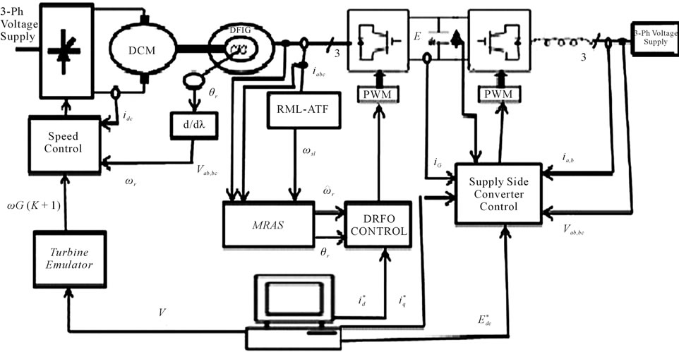
Figure 2. Experimental system.
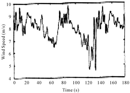
Figure 3. Wind profile in the experimental fig.
shown in Figure 4 for a wind step between 6 to 9 m/s when a wind turbine of j = 1.75 kg·m2 (JT + JG) is emulated. A wind step is not very realistic but it is the most drastic change from the control system point of view. In Figure 4, the rotor time constant is correctly estimated and the estimated speeds from the MRAS observer and RML-ATF algorithm are very good with a negligible tracking e.
Figure 5 shows the performance of the MRAS and RMLATF algorithm when a wind turbine of J = 3 kg·m2 is emulated in this test, the rotor time constant is underestimated by 50% and the tuning algorithm is off. The top graphic in Figure 5 shows the speed obtained from the encoder, MRAS and RML-ATF with a negligible error during the whole wind profile. The bottom graphic
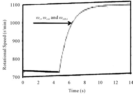
Figure 4. System Response to a wind step between 6 to 9 m/s.
in Figure 5 shows the speeds during 40 s (t = 20 to 60 s). Note that the real speed is closely tracked by the estimation obtained from the RSH.
Figure 6 shows the performance of the control system when the tuning algorithm is on. In this case the MRAS observer and the RML-ATF are tracking the real speed during the whole wind profile with very small error. The error between the estimated speed from the MRAS observer and the real speed from the encoder is almost negligible.
Figure 7 shows the speed tracking error corresponding to Figure 6. The top graphic in Figure 7 shows the tracking error of the RML-ATF algorithm and the bottom graphic shows the tracking error of the MRAS observer when the tuning of the rotor time constant is on.

Figure 5. Sensorless control using an untuned MIRAS observer.

Figure 6. control using the tuning system.

Figure 7. Speed estimation errors.
Figure 7 shows that the error of the RML-ATF algorithm is approximately ±4 r/min with some peaks of up to 7 r/min. The corresponding tracking error of the MRAS observer is ±1 r/min. The tracking error of the MRAS is similar than the error from the RML-ATF because the tuning algorithm has a reduced bandwidth, which eliminates the fast and noisy variations at the output of the RML-ATF, and also because the tuning algorithm is switched off when fast dynamic changes are detected.
Figure 8 shows the performance of the parametertuning algorithm. In t = 0, the algorithm is activated and the speed from the MRAS observer is driven to the real speed. After 2 s, the speed error is negligible. The system is operating with a wind speed of V = 8.5 m/s.
The performance of the RML-ATF algorithm and the MRAS observer for wind turbines of different inertia is shown in Table 1. Using the wind profile of Figure 3, wind turbines of J = 0.9, 1.75, and 3 kg∙m2 are emulated and the errors of the MRAS and RML-ATF estimations are obtained. Table 1 shows the average value of the error ( ) and the standard deviation of the error (σ).
For all of the wind turbines emulated in this work, the value of σ is smaller for the MRAS error than that from the RML-ATF. As mentioned previously, this is mainly because the small bandwidth of the parameter-tuning algorithm eliminates the high-frequency components of the RML-ATF. When the turbine inertia is increased, the speed tracking errors for the MRAS observer and RMLATF algorithm are reduced. For inertia values higher than 3 kg∙m2, the improvement in performance is negligible.
Figure 9 shows the real speed and the speed obtained from the RML-ATF algorithm, when the wind profile is used. Curves a, b, c correspond to inertia values of 0.9 kg∙m2, 1.75 kg∙m2, and 3 kg∙m2, respectively. The tracking of the RML-ATF algorithm is very good even for a small inertia of 0.9 kg∙m2.
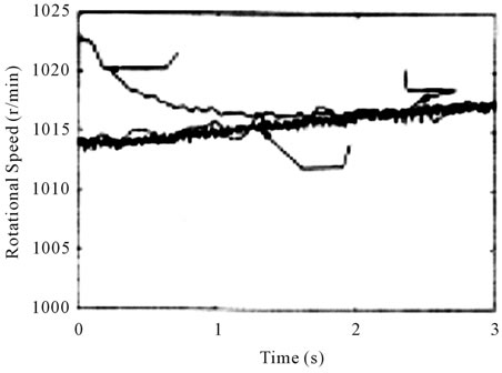
Figure 8. Control system response of the parameter tuning algorithm.
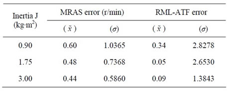
Table 1. Speed errors for mras and RML-ATF.
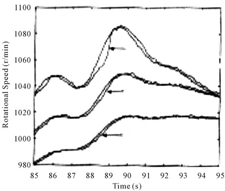
Figure 9. Control system response of the RTL-ATF for several inertial values.
The top graphic in Figure 10 shows the  current of the front-end converter when the wind profile is used (J = 0.9 kg∙m2). The bottom graphic of Figure 10 shows the corresponding dc link voltage. Despite the large and relatively fast variations in the wind speed with its corresponding variation in generated power, the dc link voltage varies less than ±2 V for the whole wind profile.
Finally, Figure 11 shows the waveform for the line current Ia, the equivalent phase voltage Van and the dc link voltage Edc for the supply side of the front-end converter when the WECS is in steady state. The system operates at the optimum tip-speed ratio with a wind velocity of 8 m/s with the front-end converter  current set to zero for close-to-unity power factor operation.
3. Conclusion
This paper has presented a new sensorless vector-control strategy for an induction generator in a variable-speed WECS using a MRAS observer to estimate the rotational speed of the induction generator. In the sensor less system, the application of a novel RML adaptive tracking filter for the estimation of the RSH has been discussed. The dynamic performance of this adaptive filter is very good and can be used to obtain an accurate estimation of the rotational speed not only in steady state but also

Figure 10. Front-end converter id current and dc link voltage.
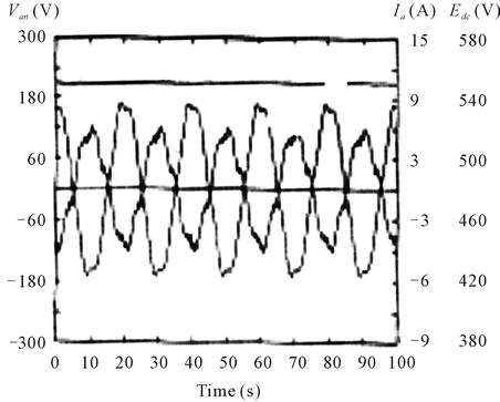
Figure 11. Voltage and current waveforms for the supply side.
when input changes fast as wind steps are applied to the WECS. Using the speed estimated from the RML-ATF algorithm, a parameter tuning control system has been implemented to improve the accuracy of the MRAS observer. When the tuning of the rotor time constant is enabled, the MRAS observer can track the speed of the wind turbine with an error of less than ±1.5 r/min for the whole range. The experimental results show that the RML-ATF algorithm could be used to tune the rotor time constant not only during steady state but also during speed transients. Experimental results have been obtained using a wind turbine emulator and an induction machine of 2.5 kW. A novel method for the emulation of highorder wind turbine models has been implemented. This emulation strategy has been used to emulate wind turbines with inertias between 0.9 kg∙m2 and 3 kg∙m2. Even wind inertia as low as 0.9 kg∙m2, the performance of the proposed sensor less control scheme is very good and the tracking of the RML-ATF is accurate. For the control of the front-end converter, an improved control structure is used. An improvement in regulation is achieved using feed forward mapping of the net dc-link disturbance current with the direct axis (real power) current component of the power converter. The experimental results have also shown the excellent performance achieved with the proposed front-end converter control strategy.
REFERENCES
- R. S. Pena, R. J. Cardens, G. M. Asher and J. C. Clare, “Vector Controlled Induction Machines for Stand-Alone Wind Energy Applications,” IEEE Industry Applications Society Annual Meeting, Rome, Vol. 3, 2000, pp. 1409- 1415.
- M. Simoes, B. Bose and R. Spigel, “Fuzzy Logic Based Intelligent Control of a Variable Speed Cage Induction Machine Wind Generation System,” IEEE Transactions on Power Electronics, Vol. 12, No. 1, 1997, pp. 87-95. doi:10.1109/63.554173
- B. Bose, “Energy, Environment, and Advances in Power Electronics,” IEEE Transactions on Power Electronics, Vol. 15, No. 4, 2000, pp. 688-701. doi:10.1109/63.849039
- C. Schauder, “Adaptive Speed Identification for Vector Control of Induction Motors without Rotational Transducers,” IEEE Transactions on Industry Applications, Vol. 28, No. 5, 1992, pp. 1054-1061. doi:10.1109/28.158829
- R. Blasco-Gimenez, G. M. Asher and M. Ummer, “Dynamic Performance Limitations for MRAS Based Sensorless Induction Motor Drives, Part 1: Stability Analysis for the Closed Loop Drive,” Electric Power Applications, Part B, Vol. 143, No. 2, 1996, pp. 113-122.
- R. Blasco-Gimenez, G. M. Asher, M. Summer and K. J. Bradley, “Dynamic Performance Limitations for MRAS Based Sensorless Induction Motor Rives, Part II: Online Parameter Tuning and Dynamic Performance Studies,” Electric Power Applications, Part B, Vol. 143, No. 2, 1996, pp. 123-134. doi:10.1049/ip-epa:19960105
- J. Jiang and J. Holtz, “High Dynamic Speed Sensor Less AC Drive with On-Line Model Parameter Tuning for Steady-State Accuracy,” IEEE Transactions on Industrial Electronics, Vol. 44, No. 2, 1997, pp. 240-246. doi:10.1109/41.564163
- A. Ferrah, K. J. Bradley. P. J. Hogben-Laing, M. S. Woolfson, G. M. Asher, M. Sumner, J. Cilia and J. Shuli, “A Speed Identifier for Induction Motor Drives Using Real-Time Adaptive Digital Filtering,” IEEE Transactions on Industry Applications, Vol. 34, No. 1, 1998, pp. 156-162. doi:10.1109/28.658741
- A. Miller, E. Muljadi and D. Zinger, “A Variable Speed Wind Turbine Power Control,” IEEE Transactions on Energy Conversion, Vol. 12, No. 2, 1997, pp. 181-186. doi:10.1109/60.629701
- E. Muljadi and C. Butterfield, “Pitch-Controlled Variable-Speed Wind Turbine Generation,” IEEE Transactions on Industry Applications, Vol. 37, No. 1, 2001, pp. 240-246. doi:10.1109/28.903156
- M. Steinbuch, “Optimal Multivariable Control of a Wind Turbine with Variable Speed,” Wind Engineering, Vol. 11, No. 3, 1987, pp. 153-163.
- J. Craig, “Dynamics of Wind Generators on Electric Utility Network,” IEEE Transactions on Aerospace and Electronic Systems, Vol. 12, 1976, pp. 483-493. doi:10.1109/TAES.1976.308329
- S. M. B. Wilmshurst, “Control Strategies for Wind Turbines,” Wind Engineering, Vol. 12, No. 4, 1988, pp. 236- 249.
- R. Cardenas, R. Peria, G. Asher and J. C. Clare, “Emulation of Wind Turbines and Flywheels for Experimental Purposes,” Proceedings Eurocon Power Electronics Conference, Graz, 27-29 August 2001.
- A. Z. Hakan, G. M. Asher and J. C. Clare, “Dynamic Emulation of Mechanical Loads Using a Vector-Controlled Induction Motor-Generator Set,” IEEE Transactions on Industrial Electronics, Vol. 46, No. 2, 1999, pp. 370-379. doi:10.1109/41.753776
- M. Wang and E. Levi, “Evaluation of Steady State and Transient Behavior of a MRAS Based Sensor Less Rotor Flux Oriented Induction Machine in the Presence of Parameter Detuning,” Electric Machines and Power Systems, Vol. 27, No. 11, 1999, pp. 1171-1190. doi:10.1080/073135699268641
- T. Thiringer and J. Linders, “Control by Variable Rotor Speed of a Fixed Pitch Wind Turbine Operating in a Wide Speed Range,” IEEE Transactions on Energy Conversion, Vol. 8, No. 3, 1993, pp. 520-526. doi:10.1109/60.257068
- “Speed Control System for a Variable Speed Wind Turbine,” US Patent 5289041, 22 February 1994.
- R. Cardenas-Dobson and G. M. Asher, “Torque Observer for the Control of Variable Speed Wind Turbines Operating Below Rated Wind Speed,” Wind Engineering, Vol. 20, No. 3, 1996, pp. 258-285.
- R. Blasco-Gimenez, G. M. Asher, M. Summer and K. J. Bradley, “Performance of FFT-Rotor Slot Harmonic Speed Detector for Sensorless Induction Motor Drives,” Proceedings of Institution of Electrical Engineering, Part C, Vol. 143, No. 3, 1996, pp. 258-268.
- S. Pei and C. Tseng, “Real Time Cascade Adaptive Notch Filter Scheme for Sinusoidal Parameter Estimation,” Signal Process, Vol. 39, No. 1-2, 1994, pp. 117-130. doi:10.1016/0165-1684(94)90128-7
- R. Cardenas, R. Peria, G. Asher and J. C. Clare, “Control Strategies for Voltage Control of a Boost Type PWM Converter,” Proceedings Power Electronics Specialist Conference, Vancouver, Vol. 2, 2001, pp. 730-735.
- “Wind Profiles, 2s Sampling Time,” Rutherford Appleton Laboratory, Chilton Didcot.
Appendix
Induction Machine: ωr (rated) = 1450 r/min, id (rated) = 1.8 A, Rs = 2.1 W, Rr = 1,7 W, Ls = 0.4186 H, L0 = 0.4058 H, Lr = 0.4186 H, σ = 0.06022.
Wind turbine Emulation: R = 1.7 m,  , Gearbox ratio= 2.12,
  , Ds = BG = Bτ
 0, JG = 0.02 kg∙m2, wind turbine emulated using a dc machine of 1500 r/min, 6.5 kW.
Nomenclature
A. General
ρ Air density.
β Pitch angle.
R Wind turbine blade radius.
Te Electrical torque.
J, B Inertia and viscous friction.
V Wind velocity.
L0, Ls, Lr Magnetizing, rotor, stator inductance.
Rr, Rs Rotor, stator resistances.
σ Induction machine leakage coefficient.
Edc DC link voltage.
Ψ Rotor flux.
P Number of pole pairs.
ωr Induction machine rotational speed.
ωT Turbine rotational speed.
ωe Electrical frequency (in radians per second).
fe Electrical frequency (in Hertz).
Tr Rotor time constant.
z Number of rotor slots.
γ Forgetting factor.
Ks Shaft compliance.
Ds Shaft viscous friction.
B. Superscripts
^ Estimated value.
* Reference value.
C. Subscripts
(α, β) Stator fixed coordinates.
(d, q) Synchronous rotating coordinates.
r, s Rotor or stator quantities.
T, G Turbine or generator quantities.

