Communications and Network
Vol.5 No.4(2013), Article ID:40139,9 pages DOI:10.4236/cn.2013.54043
Opportunistic Error Correction for OFDM-Based DVB Systems
Signals and Systems Group, University of Twente, Enschede, The Netherlands
Email: x.shao@utwente.nl, c.h.slump@utwente.nl
Copyright © 2013 Xiaoying Shao, Cornelis H. Slump. This is an open access article distributed under the Creative Commons Attribution License, which permits unrestricted use, distribution, and reproduction in any medium, provided the original work is properly cited.
Received October 1, 2013; revised November 1, 2013; accepted November 7, 2013
Keywords: DVB-T2; LDPC; BCH; Convolutional; Reed-Solomon Codes; OFDM; Fountain Codes
ABSTRACT
DVB-T2 (second generation terrestrial digital video broadcasting) employs LDPC (Low Density Parity Check) codes combined with BCH (Bose-Chaudhuri-Hocquengham) codes, which has a better performance in comparison to convolutional and Reed-Solomon codes used in other OFDM-based DVB systems. However, the current FEC layer in the DVB-T2standard is still not optimal. In this paper, we propose a novel error correction scheme based on fountain codes for OFDM-based DVB systems. The key element in this new scheme is that only packets are processed by the receiver which has encountered high-energy channels. Others are discarded. To achieve a data rate of 9.5 Mbits/s, this new approach has a SNR gain of at least 10 dB with perfect channel knowledge and 11 dB with non-perfect channel knowledge in comparison to the current FEC layer in the DVB-T2standard. With a low-complexity interpolation-based channel estimation algorithm, opportunistic error correction offers us a QEF (Quasi Error Free) quality with a maximum DF (Doppler Frequency) of 40 Hz but the current DVB-T2 FEC layer can only provide a BER of 10−7 quality after BCH decoding with a maximum DF of 20 Hz.
1. Introduction
Orthogonal Frequency Division Multiplexing (OFDM) [1-3] has recently been proposed as modulation technology for current Digital Video Broadcasting (DVB) standards (e.g. DVB-T [4], DVB-T2 [5], DVB-H [6], etc.) [7]. Although OFDM enables a rather straightforward implementation of a wireless receiver, it cannot mitigate the effects of noise and interference encountered in the transmission of signal through the wireless channel [8,9]. Therefore, error correction codes are required to achieve reliable communications [10].
For a finite block length of data to be transmitted over a frequency selective channel, coding jointly over the sub-carriers yields a smaller error probability than that can be achieved by coding separately over the sub-carriers at the same rate [9]. This theory has been applied in practical OFDM-based wireless systems (e.g. IEEE 802.11a/n [11,12], DVB-T, DVB-T2, etc.). Let us take the DVB-T2 system as an example, source bits are encoded by Low Density Parity Check (LDPC) codes [13- 15] together with Bose-Chaudhuri-Hocquengham (BCH)
codes [5,16]. An encoded packet is transmitted over all the sub-carriers like other DVB systems [4-6]. With the joint coding scheme [9], however, it is not beforehand known whether the received packet is decodable or not due to the frequency selective characteristics of the wireless channel. In such a case, the receiver tries to decode all the packets, including the ones that cannot be decoded successfully. This may lead to a waste of processing power. Furthermore, the sub-band with the deepest fading, limits the level of the noise floor that can be endured by the system, as each part of the channel is considered to be equally important in the joint coding scheme. Thereore, we propose a novel error correction layer based on fountain codes for OFDM-based DVB systems which does not have this disadvantage.
In [17], MacKay describes the encoder of a fountain coder as a metaphorical fountain that produces an unlimited number of encoded packets. Anyone who wishes to receive the source file holds a bucket under the fountain and collects enough packets. The original file can be reconstructed from the received packets. It does not matter which packet is received. The only requirement is to receive a certain number of packets [18]. In other words, fountain-encoded packets are independent to one another. This inspires us to reduce the Signal-to-Noise Ratio (SNR) requirement of the system by discarding some frequency bands of the wireless channel with deep fading. To achieve this, we encode a fountain-encoded packet with error correction codes at a relatively higher code rate and transmit it over a sub-band. By discarding some packets transmitted over the sub-bands with low energy, the noise floor can be increased and is not limited any more by the sub-band with the lowest energy.
For WLAN systems, a fountain-encoded packet can be transmitted over a single sub-carrier [19]. Multiple packets are transmitted simultaneously by using frequency division multiplexing. With this method, the receiver does not have to decode all the packets but only process the well-received packets whose SNR is higher than a threshold (i.e. corresponding to  after decoding). The fountain decoder can recover the original file by only using surviving packets. In such a case, the processing power can be reduced with respect to the traditional joint coding scheme. In addition, this method not only saves the processing power but also gives better performance compared to the FEC layer used in the current WLAN system. With the same effective throughput (i.e. 21.6 Mbits/s), this new method offers us a SNR gain of 7.5 dB in comparison with the IEEE 802.11a system [19].
Unfortunately, these results cannot be applied directly in any OFDM-based DVB systems. In the 802.11a WLAN system, the channel is considered to be timeinvariant over a MAC frame. The transmission of each fountain-encoded packet in [19] is completed within a MAC frame. Hence, the channel over a fountain-encoded packet transmission can be considered as a time-invariant flat fading channel. However, this is not the case in the DVB system. The DVB transmission system should offer sufficient flexibility to allow the reception of the services at various velocities [20]. To avoid the effects of Doppler spread, we propose to transmit the fountain-encoded packets over a set of adjacent sub-carriers. We denote such a set of sub-carriers as a sub-band. The whole transmission band is divided into a number of sub-bands. Over each sub-band, one fountain-encoded packet is transmitted. The energy of each sub-band is considered equal to the lowest energy of the sub-carriers in its subband. If a packet is transmitted over a sub-band whose energy is higher than the threshold, it will be processed by the decoder otherwise it will be discarded. Correspondingly, the processing power is reduced assuming the power consumed in the SNR comparison is negligible.
In this paper, we propose a novel approach based on fountain codes for OFDM-based DVB systems. The main contribution of this paper is to investigate whether this new method can perform better (i.e. at a lower SNR) in DVB systems than the current FEC layer defined in the DVB-T2 standard. If so, this new error correction scheme offers us a higher data rate than the current DVB systems under the same channel condition.
The outline of this paper is as follows. Opportunistic error correction is first depicted where we explain the whole idea and why we choose such a transmission scheme. In Section 3, we describe the system model that shows how we apply this novel scheme in the DVB system. After that, we compare its performance with the FEC layer from the DVB-T2 system over a TU6 channel1 [21]. The paper ends with a discussion of the conclusions.
2. Opportunistic Error Correction
Opportunistic error correction is based on fountain codes. There are several kinds of fountain codes, e.g. Luby Transform (LT) codes [22], Raptor codes [23], Online codes [24]. Opportunistic error correction is compatible with any kind of fountain code.
2.1. Fountain Codes
With fountain codes, the transmitter can generate a potentially limitless supply of fountain-encoded packets. Each fountain-encoded packet is a bitwise summation (i.e. exclusive-or-ing) of a random set of source packets [17]. Not only the selection of source packets is random, but also the number of the selected source packets is random. The receiver can reconstruct the original file by collecting enough fountain-encoded packets. The number of packets required in the receiver  is slightly larger than the number of source packets
  [17]:
[17]:
 (1)
(1)
where  is the percentage of extra packets and is called the overhead.
The mathematical principle behind fountain decoding is to solve K unknown parameters from N linear equations. It can in principle be solved by Gaussian elimination but this has a high complexity. Therefore, the message-passing algorithm [25] is usually chosen to decode fountain codes. The message-passing algorithm has a linear computation cost [17], but it requires a large  for small block size. For example, the practical overhead of LT codes is 14% when K = 2000, which limits its application in the practical system [19]. By combining message-passing algorithm with Gaussian elimination, the overhead of LT codes is reduced to 3% when K ≥ 500 [19].
With only fountain codes, we can not have opportunistic error correction for wireless systems. Fountain codes are designed for erasure channels over which the receiver either receive the packet without error or does not receive it at all. A wireless channel is not an erasure channel but a noisy fading channel, so good error correction codes should be used to make noisy channels behave like an erasure channel. Most of the time, the error correction code performs perfectly; occasionally, the decoder fails, and reports that it has failed, so the receiver knows the whole packet has been lost [17].
2.2. Transmission Schemes
Fountain codes can be applied to wireless channels, if they are combined with good error correction codes. The performance of this combination depends on how a packet is transmitted. There are two schemes to transmit a fountain-encoded packet:
• Scheme I is to transmit a packet over all the sub-carriers.
• Scheme II is to transmit a packet over a single subcarrier.
In the case of WLAN, the transmission Scheme II is chosen. Because the WLAN system is mainly designed for the reception with Doppler frequency below 10 Hz (i.e. the pedestrian and indoor reception) [20], the system can be designed in such a way that the time needed to transmit a packet is much smaller than the coherence time. That means the channel over a fountain-encoded packet can be modeled as a flat fading channel. In this case, it is possible to predict whether the received packet is decodable using the channel knowledge (i.e. SNR). Only the well received packets are processed. Correspondingly, the processing power can be reduced. Over a finite block length, Scheme I yields a smaller Bit Error Rate (BER) but a larger Packet-Error-Rate (PER) than Scheme II [26]. Fountain codes only need enough errorfree fountain-encoded packets to reconstruct the original file. Therefore, with fountain codes in the IEEE 802.11a system, Scheme II performs better (i.e. an SNR gain of 5 dB with QAM-16 modulation scheme) than Scheme I at the same code rate (i.e. R = 0.5) [26].
However, the DVB system is different from the WLAN system. In DVB, the receivers are moving at different velocities (corresponding to different Doppler spreads). Also, the DVB system utilizes a large number of sub-carriers ranging between 1 k and 32 k to have high spectrum efficiency. The higher the spectrum efficiency, the more sensitive to Doppler spread. In this paper, we focus on the 8 k mode. To reduce the delay as much as possible, we make the fountain-encoded packet short such that it does not occupy the whole band-width with the transmission Scheme I. Due to Doppler spread, the channel over a packet is not a flat-fading channel regardless with Scheme I or with Scheme II. Which one to choose depends on the following:
• During the transmission of a packet, the channel should be as flat as possible.
• During the transmission of a packet, the dynamic range D of the channel should not be affected by the variation of Doppler spread.
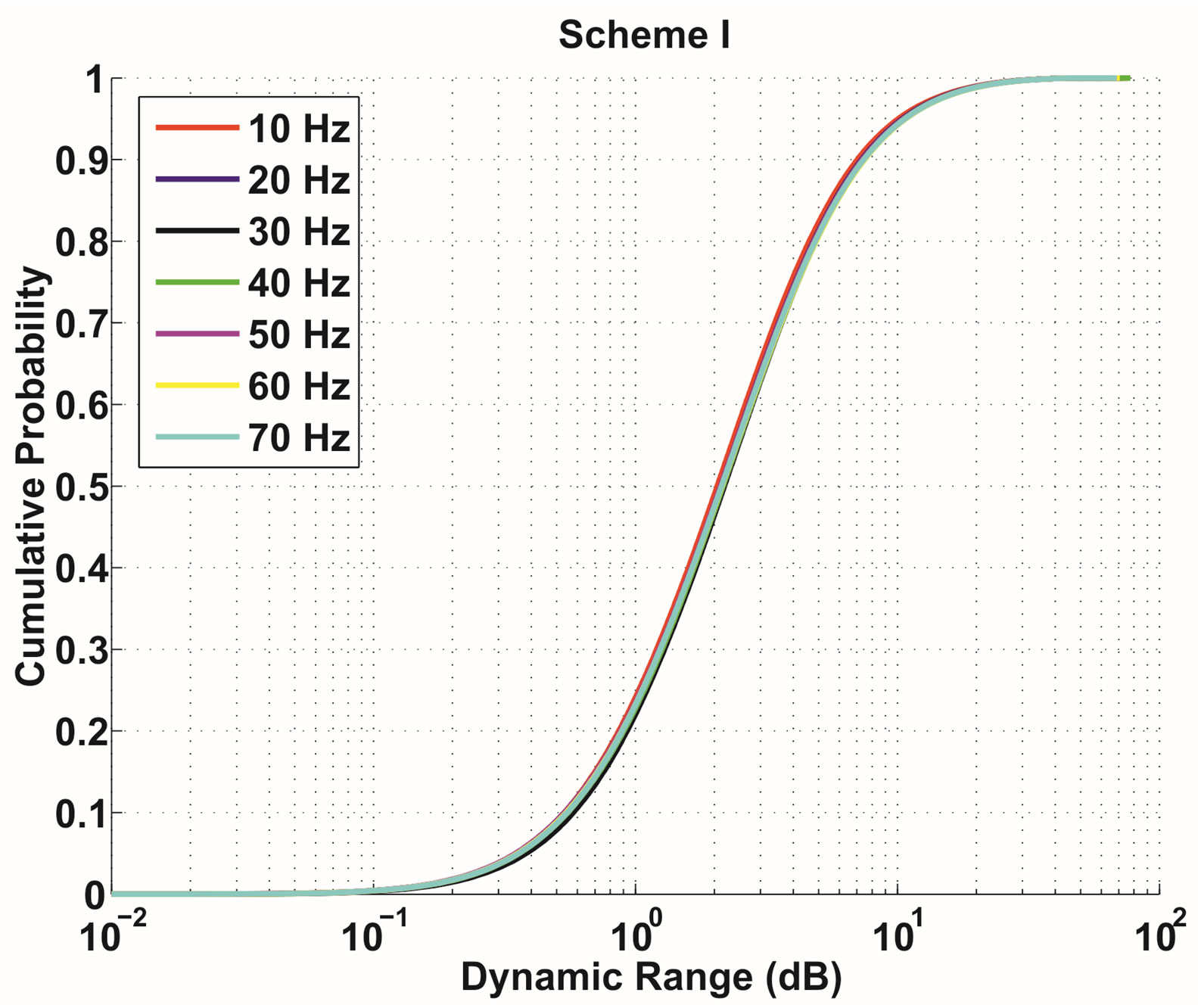
Figure 1 shows the difference in between the use of the transmission Schemes I and II. Obviously, Scheme II is more sensitive to the variation of Doppler Frequency (DF) than Scheme I. With Scheme I, around 80% of packets can be transmitted over a channel with D ≤ 5 dB as DF varies from 10 to 70 Hz. With Scheme II, D increases with DF. When DF = 10 Hz, only 10% packets can be transmitted over the channel with D ≤ 5 dB; however, the percentage is decreased to around 3% for DF = 20 dB. For DF ≥ 30 Hz, almost all the packets have to be transmitted over a channel with D > 5 dB. Therefore, we choose Scheme I to transmit a fountain-encoded packet in the DVB system.
 (a)
(a)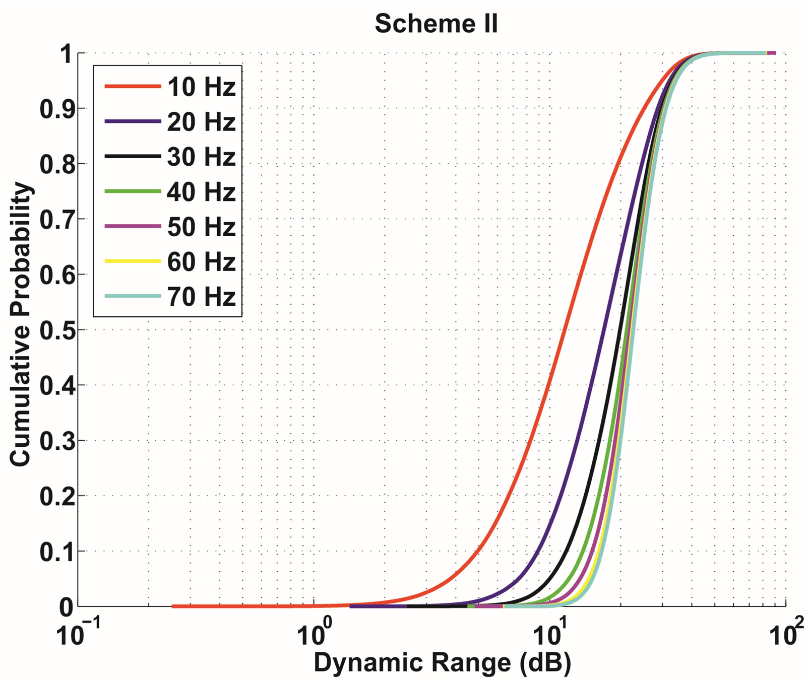 (b)
(b)
Figure 1. The cumulative probability of the channel’s dynamic range D over a fountain-encoded packet: the transmission Scheme I (top) and the transmission Scheme II (bottom). (a) Transmission Scheme I; (b) Transmission Scheme II.
2.3. Opportunistic Error Correction
Opportunistic error correction is based on fountain codes and good error correction codes. In this paper, we employ LT codes as fountain codes and LDPC [27] plus Cyclic Redundancy Check (CRC) [28] to make the wireless channel behave like an erasure channel. To reduce the overhead of LT codes for small K, we use the message-passing algorithm with Gaussian elimination to decode the LT codes.
Our FEC encoding scheme is performed in the following order: K source packets are encoded by LT codes first. To each fountain-encoded packet, a CRC is first added and the resulting packet is encoded by a LDPC code. Each packet is transmitted in a single sub-band. It is a cross-coding scheme over all the sub-bands, as source data is first encoded jointly over all the sub-bands by LT codes then encoded separately over a single subband by LDPC plus CRC codes. That is different from the FEC layer in the DVB standards, which is based on the joint coding scheme over all the sub-bands.
At the receiver, each fountain-encoded packet is first LDPC decoded when the SNR of its sub-band is equal to or higher than the threshold. The received packet is discarded if its energy is below the threshold. If LDPC decoding fails, the packet is discarded as well. If LDPC decoding succeeds, CRC is used to identify whether there are undetected errors from LDPC codes. If CRC decoding fails, the receiver also assumes that the whole packet has been lost. Once the receiver collects N surviving fountain-encoded packets, it starts to recover source data.
3. System Model
The opportunistic error correction scheme has been explained in the above section. The proposed approach can be applied in any OFDM-based DVB system. In this paper, the SISO DVB-T2 system is taken as an example of DVB systems.
The FEC layer in the current DVB-T2 system is based on LDPC codes and BCH codes. The concatenated LDPC-BCH codes assure a better protection than the FEC layer in the DVB-T system, which is based on convolutional and Reed-Solomon codes [5]. To reduce burst bit errors, interleaving is employed after the LDPC-BCH encoder in the DVB-T2 system. As mentioned earlier, the encoded packet is transmitted over all the sub-bands. Although this solution works well in practical systems, it is not optimal. Because it cannot be beforehand predicted whether the received packet is decodable even with a perfect channel knowledge. Packets that have encountered a low-energy channel are still processed by the decoders. That can waste processing power. Also, the performance of this joint-coding approach is limited to the sub-bands with low energy, as it treats each part of the channel equally important.
In Figure 2, the proposed opportunistic error correction scheme is depicted. The key idea is to generate additional packets by fountain encoding. First, source packets are encoded by the fountain encoder. Then, a CRC checksum is added to each fountain-encoded packet and LDPC encoding is applied afterwards. On each sub-band, a packet is transmitted. Thus, multiple packets are transmitted simultaneously, using frequency division multiplexing. With this method, interleaving is not required.
At the receiver side, we assume that synchronization is perfect. A dynamic estimation of the channel is necessary after the demodulation of OFDM signals, as the wideband mobile communication system transmits data over a time-variant frequency selective fading channel [1]. The channel estimation in the DVB system is based on a set of scattered pilots inserted into each OFDM symbol (i.e. the comb-type pilot). In total, there are 8 types of pilot patterns defined in the DVB-T2 standard [5]. In this paper, we utilize the PPI pattern to estimate the channel as shown in Figure 3. The scattered pilots are estimated by the zero-forcing algorithm:
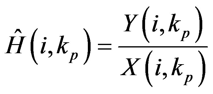 (2)
(2)
where  is the
  received pilot tone and
  is the
 transmitted pilot tone at the i-th OFDM symbol.
With , the channel information of the data sub-carriers can be estimated by interpolation. Generally it is a two-dimensional interpolation problem but it can be separated into a one-dimensional interpolation in time
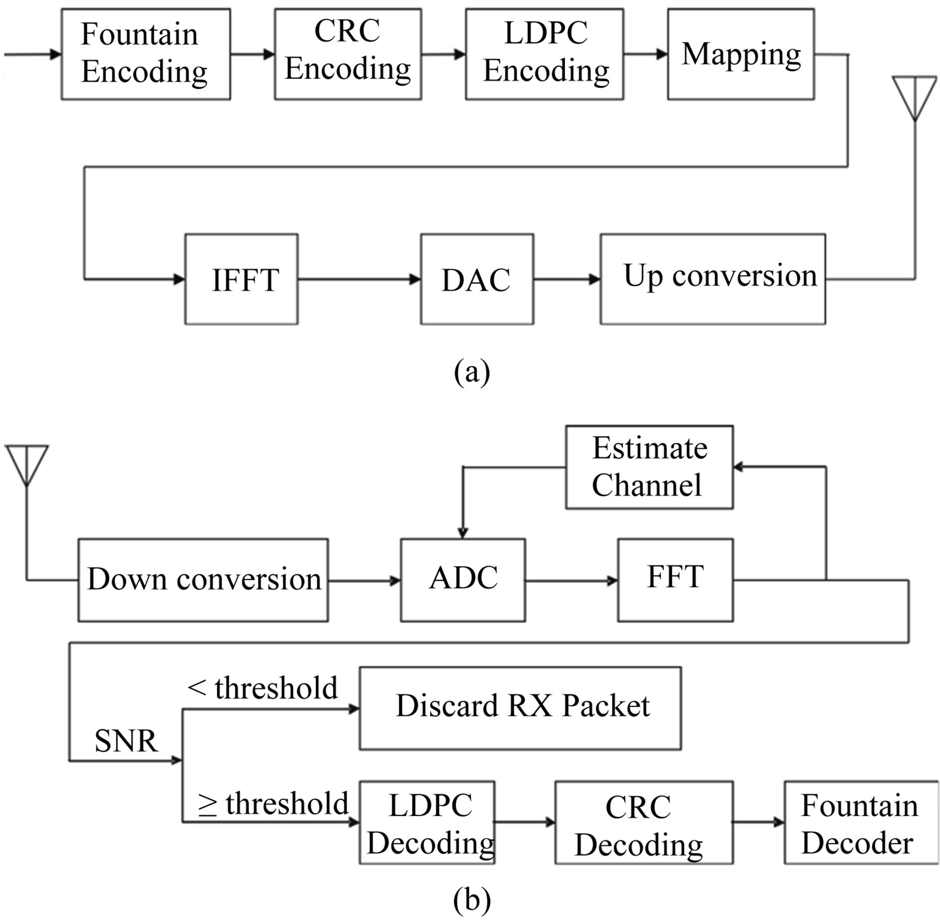
Figure 2. Proposed DVB-T2 transmitter (top) and receiver (bottom). (a) Transmitter; (b) Receiver.
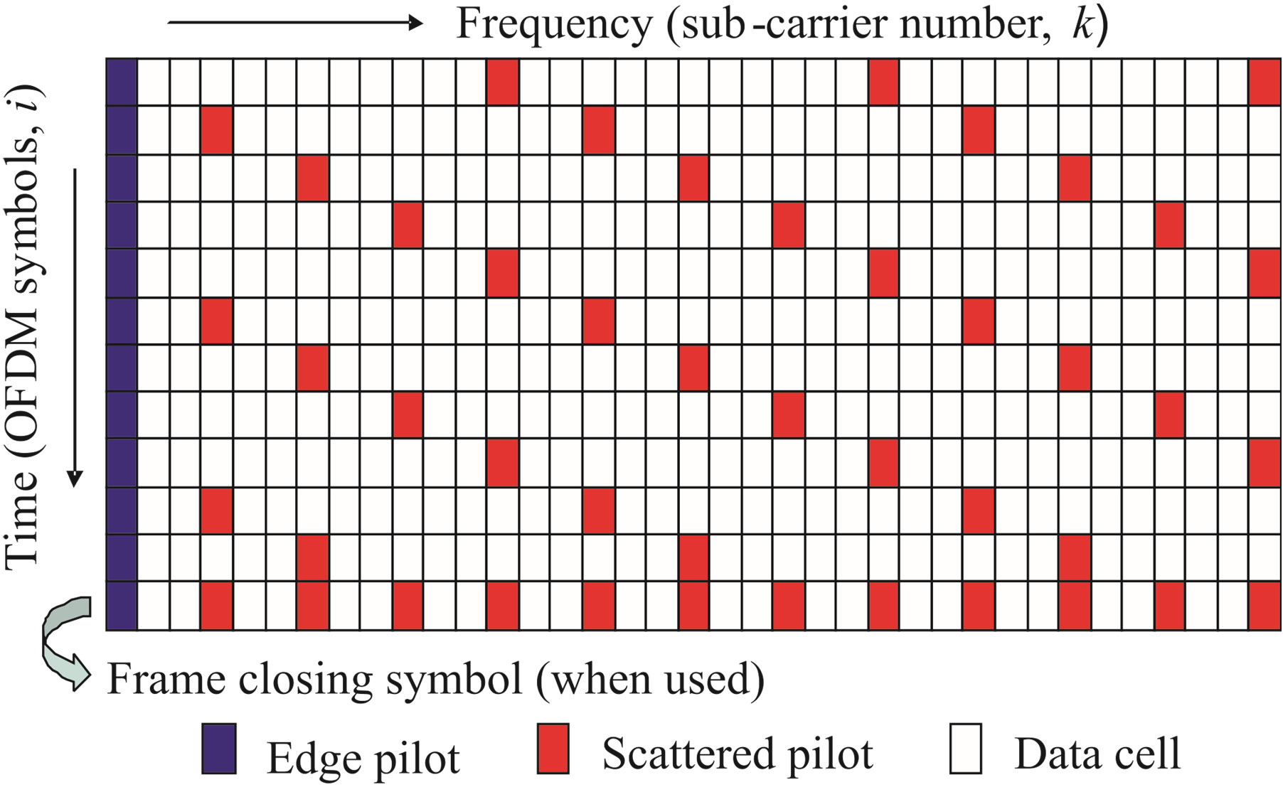
Figure 3. Scattered pilot pattern PPI (SISO) [5].
and in frequency for a low-complexity system implementation [29]. There are several types of interpolation algorithms, e.g. linear interpolation, second order interpolation, low-pass interpolation [30]. In this paper, for the sake of simplicity, the linear interpolation is used in the time domain and the low-pass interpolation is employed for the frequency domain.
In the time domain, the channel information at the  data-carrier of the i-th OFDM,
  , is estimated by [30]:
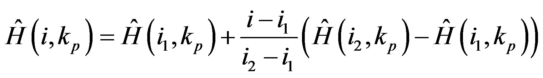 (3)
(3)
where  and
and  are the estimated channel information of scattered pilots at the
  and
and  OFDM symbols, respectively. With
 , the low-pass interpolation is performed in the frequency domain by inserting zeros into the original sequence. Then, a low-pass FIR filter is applied to minimize the meansquare error between the interpolated points and their ideal values [30]. So, the channel information of the
  data sub-carrier at the
  OFDM symbol is estimated by:
 (4)
(4)
where  is the coefficient of the low-pass filter.
With the channel knowledge, the receiver can decide whether the received packet should be processed. If the SNR of the sub-band is equal to or above the threshold, the received packet will go through the LDPC decoding otherwise it will be discarded. This means that the receiver do not process all the packets but only the wellreceived packets. Correspondingly, the processing power is reduced. If the channel is perfectly estimated, this can be done. However, the channel estimation is based on interpolation with limited accuracy. In such a case, the receiver can hardly predict correctly whether the received packet is decodable with a high probability. That degrades its performance. To avoid this, the receiver will process all the fountain-encoded packets with the nonperfect channel estimation. The received packets can only survive if they pass LDPC decoding and CRC decoding successfully. When the receiver has collected enough fountain-encoded packets, it starts to recover the source data by using the message-passing algorithm and Gaussian elimination together.
4. Performance Comparison
In this section, we analyze the performance of opportunistic error correction in the OFDM-based DVB system. The DVB-T2 system is taken as an example of OFDMbased DVB systems, as the LDPC-BCH codes in the DVB-T2 standard work better than the convolutional and Reed Solomon codes in other OFDM-based DVB systems. We compare opportunistic error correction with the FEC scheme from the DVB-T2 standard in the simulation. There are two main differences between both FEC schemes. First, the proposed FEC scheme is a cross coding scheme over the sub-bands, while the DVB-T2 FEC scheme is a joint coding scheme over all the sub-bands. Second, the proposed cross coding scheme does not require interleaving, but the DVB-T2 FEC scheme does need interleaving to avoid burst errors. For each simulation point, we transmit more than 1000 bursts of data (i.e. around 100 million bits) over a 8 MHz TU6 channel with a certain DF. Each burst consists of 512 source packets with a length of 168 bits. With the same data rate of 9.5 Mbits/s (i.e. QAM-16 modulation with code rate R = 0.434), a source file is encoded by opportunistic error correction and the LDPC-BCH code from the DVB-T2 standard, respectively. Then, the bits encoded by the DVB-T2 FEC scheme are interleaved according to the DVB-T2 standard [5]. Afterwards, they are mapped into QAM-16 symbols before OFDM modulation.
With opportunistic error correction, each burst is encoded by a LT code (with parameter ) and decoded by the message-passing algorithm and Gaussian elimination together. Only 3% overhead is required to reconstruct the original data successfully [19]. To each fountain-encoded packet, a 7-bit CRC is added before the (175, 255) LDPC encoding is applied. Under the condition of the same code rate (i.e. R = 0.434), we are allowed to discard around 32% of the packets2.
With the FEC layer defined in the DVB-T2 standard, source bits are first encoded by the (7032, 7200) BCH code then by the (7200, 16200) LDPC code. To reduce burst bit errors, bits are interleaved and de-multiplexed into cells afterwards [5]. The DVB-T2 system is designed to provide a “Quasi Error Free” (QEF) quality target [5]. The definition of QEF adopted for DVB-T2 is “less than one uncorrected error-event per transmission hour at the level of a 5 Mbit/s single TV service decode”, approximately corresponding to a Transport Stream Packet Error Ratio PER < 10−7 (i.e. BER < 10−11) before the de-multiplexer which is equivalent to BER < 10−7 after LDPC decoding [5]. To keep simulation times reasonable, we choose a BER of 10−4 after LDPC decoding as the comparison criterion, which corresponds to approximately a BER of 10−7 after BCH decoding [31].
As stated earlier, the interpolation-based channel estimation mentioned in section III is not optimal, but it is employed by the practical DVB systems due to its low implementation complexity. To show how robust both FEC layers are to the channel estimation errors, they are compared in two situations: with perfect channel knowledge and with non-perfect channel knowledge.
4.1. With Perfect Channel Knowledge
In this case, we assume that the receiver has a perfect knowledge of the channel. As shown in Figure 1, the dynamic range of sub-bands based on the transmission method I is not affected by Doppler spread. In other words, the BER performance does not change with Doppler frequency as revealed in the simulation. Figure 4 shows the simulation results over the TU6 channel. Obviously, our opportunistic error correction scheme performs much better than the FEC layer in the DVB-T2 standard. To reach a BER of 10−7 after BCH decoding (i.e. a BER of 10−4 after LDPC decoding), the current DVB-T2 system should have a SNR of at least 28 dB at a data rate of 9.5 Mbits/s. With our opportunistic error correction method, the proposed DVB-T2 system has error free when SNR = 18 dB. That means our method gains a SNR of more than 10 dB at a data rate of 9.5 Mbits/s for a BER of 10−7.
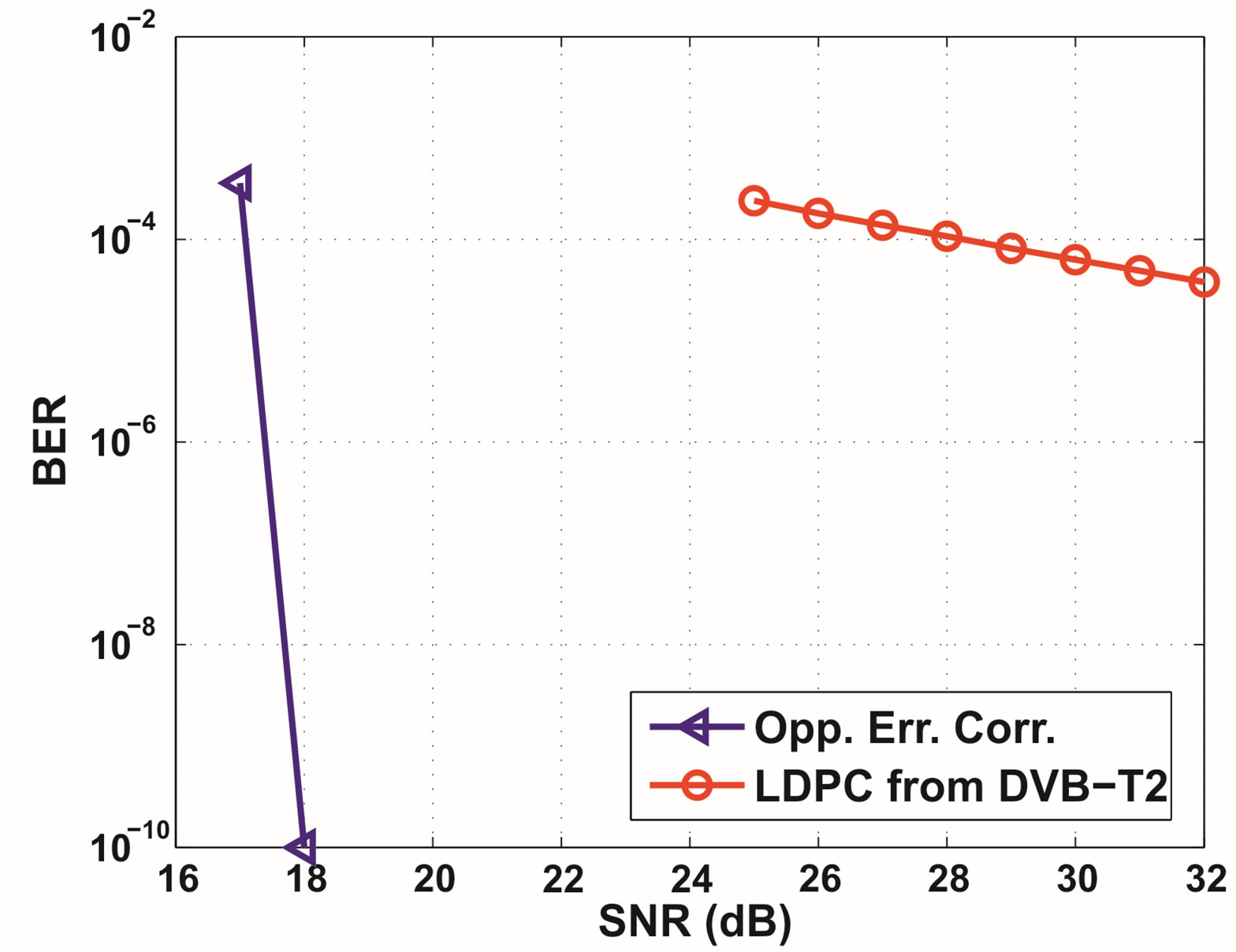
Figure 4. BER comparison between opportunistic error correction and the (7200, 16200) LDPC code from the DVBT2 standard in the noisy TU6 channel with perfect channel estimation. For opportunistic error correction, no error occurs when SNR ≥ 18 dB. So for this point, we represent BER = 0 by 10−10.
However, if we compare them under the QEF criterion, opportunistic error correction will gain a SNR of at least 14 dB with respect to the FEC layer in the DVB-T2 standard (i.e. a BER of 10−7 after LDPC decoding).
4.2. With Non-Perfect Channel Knowledge
In this part, we investigate the side-effect of the channel estimation error to both FEC schemes. As described in Section 3, the channel estimation in the DVB system is based on scattered pilot sub-carriers. The estimation accuracy of the pilot sub-carries directly affects the estimation of the data sub-carriers. In a frequency selective channel, it is very likely that some pilot sub-carriers will suffer deep fading. With the zero-forcing algorithm, this results in a huge estimation error that directly influences the channel estimation of data sub-carriers. In order to see the penalty of the noise on the pilot sub-carriers for both FEC schemes, we compare them over the TU6 channel without noise and with noise, separately.
1) Noiseless Channel: In this case, pilot sub-carriers are perfectly estimated and data sub-carriers are estimated by the interpolation algorithm as depicted in Section 3. Figure 5 shows the simulation results. Obviously, the BER performance degrades when DF increases. Opportunistic error correction is error free till DF = 40 Hz but that does not happen in the DVB-T2 FEC layer. When DF = 50 Hz, opportunistic error correction has higher BER than the FEC layer from the DVBT2 standard. That is because opportunistic error correction does not have enough error-free packets to reconstruct the original file. Since there is no feed-back channel in the DVB systems, in this case the receiver either cannot recover source data or use some packets in error3 to reconstruct the original file. In our simulation, we choose the second option. If the fountain decoder utilizes packets in error, bit errors will propagate during the decoding. This is the disadvantage of using fountain codes as a FEC scheme without a feedback channel. However, the BER of the LDPC code from the DVB-T2 standard is 1.14 × 10⁻³ at DF = 50 Hz and is also not acceptable. Only when  Hz, the current DVBT2 system has a BER less than
  after LDPC decoding. Furthermore, it is impossible for the current DVB-T2 system to achieve the QEF target with the interpolation-based channel estimation at a data rate of 9.5 Mbits/s. But, opportunistic error correction can offer us the QEF quality using this low-accurate and lowcomplexity channel estimation algorithm. Therefore, we conclude that opportunistic error correction works better than the DVB-T2 FEC layer in the noiseless TU6 channel with the non-perfect channel knowledge.
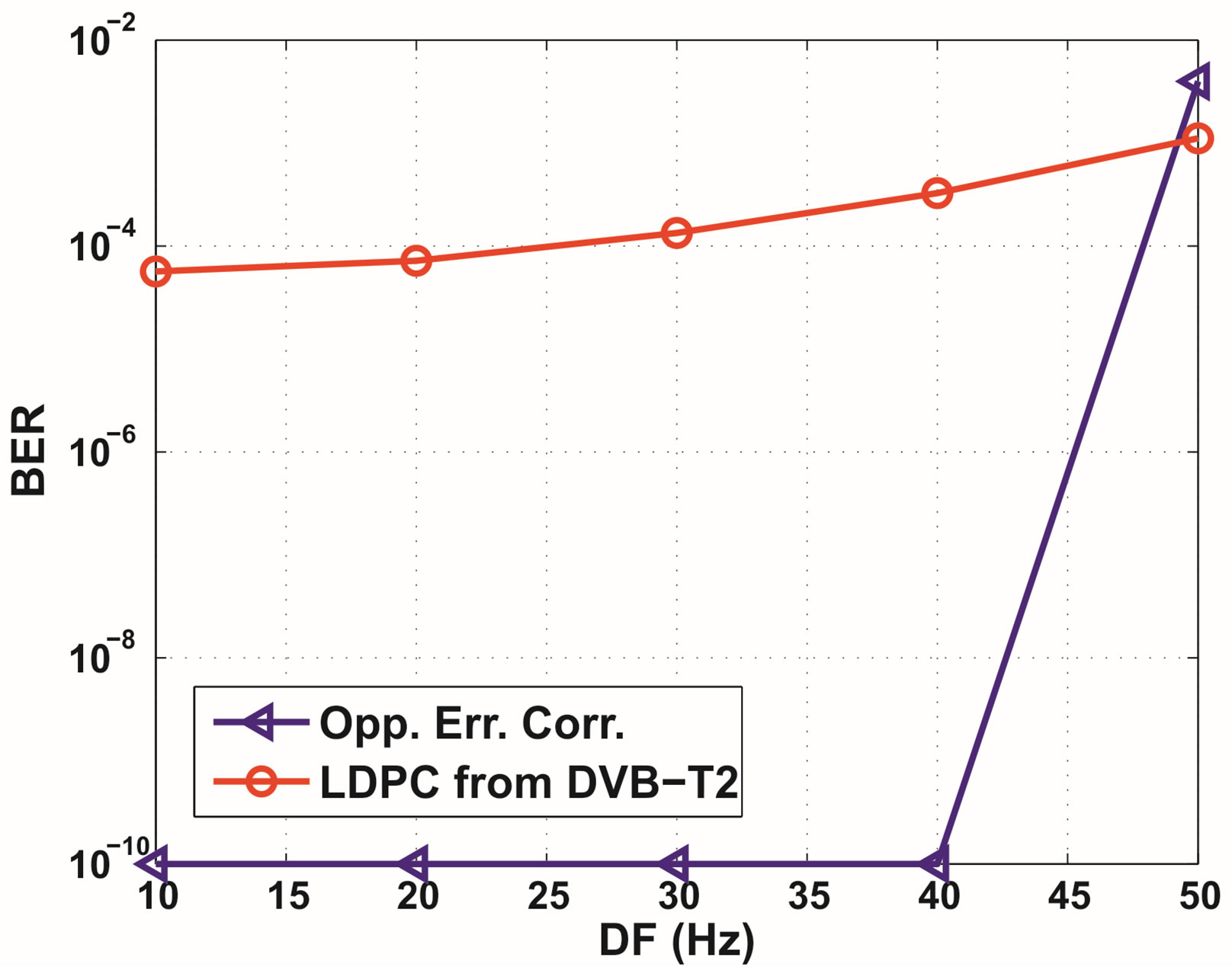
Figure 5. BER comparison between opportunistic error correction and the FEC layer in the DVB-T2 standard in the noiseless TU6 channel with the non-perfect channel estimation. For opportunistic error correction, no error occurs when DF = 10 - 40 Hz. So for those points, we represent BER = 0 by 10−10.
2) Noisy Channel: In practice, the channel estimation does suffer from inaccuracies caused both by imperfect interpolation and by the presence of noise on the pilot cells. Figure 6 shows the practical performance of opportunistic error correction over a TU6 channel at DF ≤ 40 Hz. As we can see, opportunistic error correction still provides us the error-free quality even with the nonperfect estimation in the pilot cells. Larger DF requires higher SNR to achieve BER = 0. When  Hz, there is 1 dB SNR loss as DF increases by 10 Hz. In the case of DF increase from 30 Hz to 40 Hz, there is a 7 dB SNR loss. A more accurate channel estimation algorithm is required for OFDM-based DVB systems when DF > 30 Hz.
As just discussed, it is impossible for the current DVB-T2 system to have a BER of  when DF > 20 Hz. So, we only investigate the practical performance of the (7200, 16200) LDPC code over a noisy TU6 channel with
  Hz. The simulation results are shown in Figure 7. To achieve a BER of
  after BCH decoding (i.e. a BER of
  after LDPC decoding), it needs around 34 dB for DF = 10 Hz and around 36 dB for DF = 20 Hz at a data rate of 9.5 Mbits/s. It has a 2 dB SNR loss as the DF increases by 10 Hz which is twice as the opportunistic error correction. Furthermore, opportunistic error correction gains a SNR of more than 11 dB for DF = 10 Hz and more than 12 dB for DF = 20 Hz over a noisy TU6 channel with the non-perfect channel estimation.
Simulation results have showed that opportunistic error correction wins the DVB-T2 FEC scheme with a significant gain. The reason behind is as follows. Due to the variation of the channel, a burst data encounters several channels with different fading patterns. In total, opportunistic error correction allows 32% packets to be
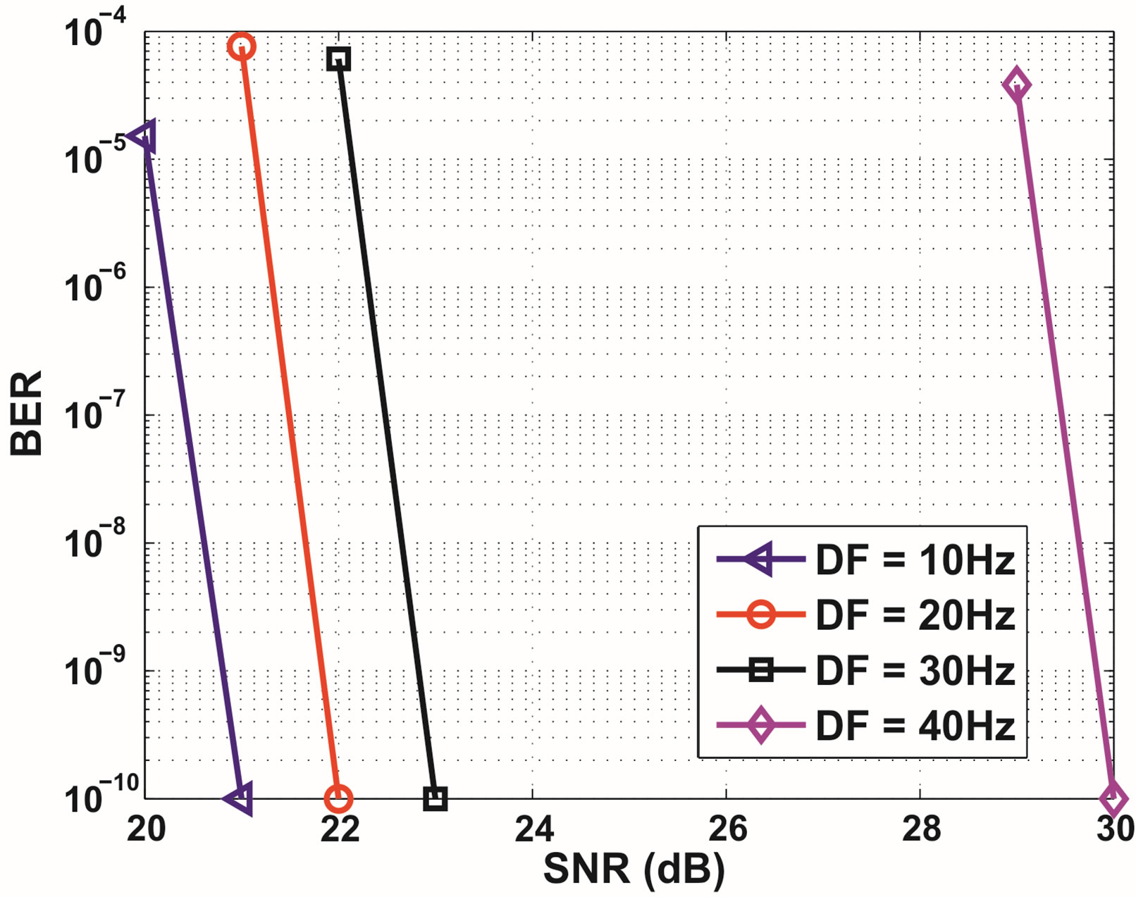
Figure 6. BER performance of opportunistic error correction in the noisy TU6 channel with the non-perfect channel estimation. For DF = 10 Hz, no error occurs at SNR = 21 dB. So for this point, we represent BER = 0 by 10−10. Same for DF = 20 - 40 Hz.
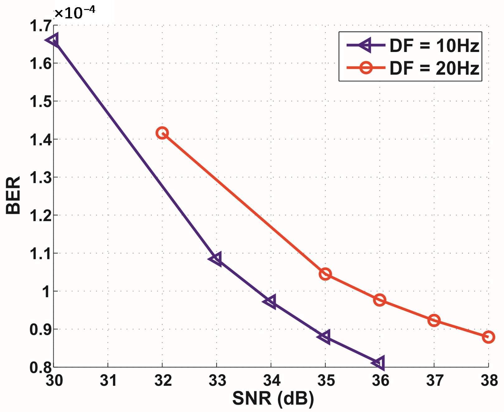
Figure 7. BER performance of the (7200, 16200) LDPC code from the DVB-T2 standard in the noisy TU6 channel with the non-perfect channel estimation.
discarded. If one channel is in “bad fading condition” that results in more than 32% packet loss, fountain codes still can compensate this loss from other channels that has less than 32% packet loss, and thus recover source data correctly. However, this does not occur to the DVB-T2 FEC scheme. The performance of error correction codes depends not only on the AWGN noise level but also on the channel fading. Because of the randomness of the channel, there is a significant probability that the channel is in a “bad fading condition” that the joint coding scheme from DVB-T2 could not decode them successfully, which cannot be compensated. That explains why the proposed coding scheme outperforms the DVB-T2 FEC scheme and why the BER curve for the DVB-T2 FEC scheme does not decay quickly.
5. Conclusions
In this paper, we propose a novel error correction scheme based on fountain codes for OFDM-based DVB systems. It is called opportunistic error correction because the receiver is allowed to discard packets. By transmitting a fountain-encoded packet over a single sub-band, the receiver does not have to take care of all the sub-bands (i.e. all the received packets) but only the sub-bands with high energy (i.e. the packets with high SNR). Fountain codes can reconstruct the original file by only using surviving packets. Just like the water-filling algorithm, we increase the data rate over stronger sub-bands by sacrificing the weak ones. In such a case, the total data rate over a frequency selective fading channel can be increased. Equivalently, given a certain data rate, opportunistic error correction endures higher noise floor (i.e. lower SNR) than the joint coding scheme. With perfect channel knowledge, opportunistic error correction has a SNR gain of at least 10 dB in comparison to the FEC layer from the DVB-T2 standard at a data rate of 9.5 Mbits/s.
In addition, opportunistic error correction survives in the low-accuracy interpolation-based channel estimation when DF ≤ 40 Hz but that does not happen with the current DVB-T2 FEC layer. With this low-complexity channel estimation, opportunistic error correction offers us the QEF quality with a maximum DF of 40 Hz but the current DVB-T2 FEC layer can only provide a BER of 10−7 quality after BCH decoding with a maximum DF of 20 Hz. Furthermore, our new approach gives us a SNR gain of more than 11 dB with non-perfect channel estimation over a noisy TU6 channel in comparison to the current FEC layer in the DVB-T2 standard. Unlike the DVB-T2 FEC layer (the joint coding scheme), opportunistic error correction only utilizes stronger sub-bands that can be more correctly estimated than the weak ones. That explains why there is a higher gain in the case of nonperfect channel estimation than the case with the perfect channel estimation. As the concatenated LDPC-BCH codes yields a better protection than the convolutional and Reed-Solomon codes used in other OFDM-based DVB systems [5], we can conclude that opportunistic error correction performs better over a TU6 channel than the FEC layer in current OFDM-based DVB systems. Therefore, we suggest considering this new scheme as a candidate of the FEC layer for the next generation OFDM-based DVB systems.
6. Acknowledgements
The authors acknowledge the Dutch Ministry of Economic Affairs under the IOP Generic Communication— SenterNovem Program for the financial support.
REFERENCES
- A. R. S. Bahai, B. R. Saltzberg and M. Ergen, “MultiCarrier Digital Communications: Theory and Applications of OFDM,” Springer Verlag, New York, 2004.
- H. Liu and G. Li, “OFDM-Based Broadband Wireless Networks, Design and Optimization,” Wiley, Hoboken, 2005. http://dx.doi.org/10.1002/0471757195
- M. Engels, “Wireles OFDM Systems: How to Make them Work?” Kluwer Academic Publisher, Norwell, 2002. http://dx.doi.org/10.1007/b117438
- “Digital Video Broadcasting (DVB): Framing Structure, Channel Coding and Modulation for Digital Terrestrial Television,” ETSI EN 300 744, V.1.5.1, European Telecommunications Standards Institute, 2004.
- “Framing Structure, Channel Coding and Modulation for a Second Generation Digital Terrestrial Television Broadcasting System (DVB-T2),” European Telecommunications Standards Institute, 2008.
- “Digital Video Broadcasting (DVB); Transmission System for Handheld Terminals (DVB-H),” European Telecommunications Standards Institute, 2004.
- U. Reimers, “DVB: The Family of International Standards for Digital Video Broadcasting,” Springer-Verlag, New York, 2005.
- A. B. Carlson, “Communication Systems: An Introduction to Signal and Noise in Electrical Engineering,” McGraw-Hill, New York, 1986.
- D. Tse and P. Viswanath, “Fundamentals of Wireless Communication,” Cambridge University Press, New York, 2005. http://dx.doi.org/10.1017/CBO9780511807213
- R. G. Gallager, “Information Theory and Reliable Communication,” John Wiley & Sons, Inc., New York, 1968.
- IEEE, “Wireless LAN Medium Access Control (MAC) and Physical Layer (PHY) Specifications, High-Speed Physical Layer in the 5 GHz Band,” IEEE 802.11a Standard, Part 11, 1999.
- IEEE, “Draft Standards for wireless LAN Medium Access Control (MAC) and Physical Layers (PHY) Specifications, Enhancements for Higher Throughput,” IEEE 802.11n Standard, Part 11, 2007.
- R. G. Gallager, “Low-Density Parity-Check Codes,” MIT Press, Cambridge, 1963.
- D. MacKay and R. Neal, “Good Codes Based on Very Sparse Matriices,” In: D. MacKay and R. Neal, Eds., Cryptography and Coding, Lecture Notes in Computer Science, Springer, Berlin/Heidelberg, 1995, pp. 100-111.
- T. Richardson, M. Shokrollahi and R. Urbanke, “Design of Capacity-Approaching Irregular Low-Density ParityCheck Codes,” IEEE Transactions on Information Theory, Vol. 47, No. 2, 2001, pp. 619-637. http://dx.doi.org/10.1109/18.910578
- S. Lin and D. J. Costello, “Error Control Coding: Fundamental and Applications,” Prentice-Hall, Englewood Cliffs, 1983.
- D. Mackay, “Fountain Codes,” IEEE Communications, Vol. 152, No. 6, 2005, pp. 1062-1068. http://dx.doi.org/10.1049/ip-com:20050237
- M. Mitzenmacher, “Digital Fountains: A Survey and Look Forward,” IEEE Information Theory Workshop, San Antonio, 24-29 October 2004, pp. 271-276.
- X. Shao, R. Schiphorst and C. H. Slump, “An Opportunistic Error Correction Layer for OFDM Systems,” EURASIP Journal on Wireless Communications and Networking, Vol. 2009, 2009, Article ID: 750735. http://dx.doi.org/10.1155/2009/750735
- G. Faria, J. A. Henriksson, E. Stare and P. Talmola, “DVB-H: Digital Broadcasting Services to Handheld Devices,” Proceedings of the IEEE, Vol. 94, No. 1, 2006, pp. 194-209.
- M. Failli, “Digital Land Mobile Radio Communications COST 207,” European Commission, EUR, 1989.
- M. Luby, “LT Codes,” Proceedings of the 43rd Annual IEEE Symposium on Foundations of Computer Science, Vancouver, 16-19 November 2002, pp. 271-282.
- A. Shokrollahi, “Raptor Codes,” IEEE Transactions on Information Theory, Vol. 52, No. 6, 2006, pp. 2551-2567.
- P. Maymounkov, “Online Codes,” Research Report TR 2002-833, New York University, New York, 2002.
- D. MacKay, “Information Theory, Inference and Learning Algorithms,” Cambridge University Press, Cambridge, 2003.
- X. Shao and C. H. Slump, “A Novel Cross Coding Scheme for OFDM Systems,” IEEE Information Theory Workshop (ITW), Taormina, 11-16 October 2009, pp. 445-449.
- Y. Kou, S. Lin and M. Fossorier, “Low-Density Parity-Check Codes Based on Finite Geometries: A Rediscovery and New Results,” IEEE Transactions on Information Theory, Vol. 47, No. 7, 2001, pp. 2711-2736. http://dx.doi.org/10.1109/18.959255
- W. Peterson and D. Brown, “Cyclic Codes for Error Detection,” Proceedings of the IRE, Vol. 49, No. 1, 1961, pp. 228-235. http://dx.doi.org/10.1109/JRPROC.1961.287814
- M. Speth, S. Fechtel, G. Fock and H. Meyr, “Optimum Receiver Design for OFDM-Based Broadband Transmission—Part II: A Case Study,” IEEE Transactions on Communications, Vol. 49, No. 4, 2001, pp. 571-578. http://dx.doi.org/10.1109/26.917759
- S. Coleri, M. Ergen, A. Puri and A. Bahai, “Channel Estimation Techniques Based on Pilot Arrangement in OFDM Systems,” IEEE Transactions on Broadcasting, Vol. 48, No. 3, 2002, pp. 223-229. http://dx.doi.org/10.1109/TBC.2002.804034
- ETSI: “Implementation Guidelines for DVB Terrestrial Services: Transmission Aspects,” ETSI Technical Report TR 101 190 V1.1.1 (1997-12).
NOTES
1TU6 channel: the Typical Urban 6-pathchannel model.
2 , where R is the effective code rate (i.e. 0.434), R1 is the code rate of LT codes (i.e. 1/1.03 ≈ 0.97) and R2 is the code rate of the (175, 255) LDPC code with 7-bit CRC (i.e. 168/255 ≈ 0.66).
3Packets in error refer to those that cannot pass the error correction decoding.